JP2010053966A - Dynamic damper - Google Patents
Dynamic damper Download PDFInfo
- Publication number
- JP2010053966A JP2010053966A JP2008220008A JP2008220008A JP2010053966A JP 2010053966 A JP2010053966 A JP 2010053966A JP 2008220008 A JP2008220008 A JP 2008220008A JP 2008220008 A JP2008220008 A JP 2008220008A JP 2010053966 A JP2010053966 A JP 2010053966A
- Authority
- JP
- Japan
- Prior art keywords
- inner cylinder
- mass
- cylinder member
- dynamic damper
- protrusion
- Prior art date
- Legal status (The legal status is an assumption and is not a legal conclusion. Google has not performed a legal analysis and makes no representation as to the accuracy of the status listed.)
- Granted
Links
Images


Abstract
Description
本発明は、ダイナミックダンパに関し、特に、制振対象部材の共振周波数による振動の増幅を抑制することができるダイナミックダンパに関する。 The present invention relates to a dynamic damper, and more particularly to a dynamic damper that can suppress amplification of vibration due to a resonance frequency of a member to be damped.
従来から、共振周波数による振動の増幅を抑制するために、制振対象部材にダイナミックダンパを取付けたものが知られている。このダイナミックダンパは、制振対象部材に対して弾性体を介して質量体が弾性的に支持されるようになっており、ダイナミックダンパの固有振動数を制振対象部材の共振周波数にチューニングすることにより、特定の周波数域の振動に対して制振効果を発揮するようにしている。具体的には、質量体の質量と弾性体の剛性(ばね定数)を適当に設定することにより、ダイナミックダンパの固有振動数がチューニングされるようになっている。 2. Description of the Related Art Conventionally, in order to suppress vibration amplification due to a resonance frequency, a member provided with a dynamic damper on a vibration suppression target member is known. In this dynamic damper, the mass body is elastically supported via the elastic body with respect to the vibration suppression target member, and the natural frequency of the dynamic damper is tuned to the resonance frequency of the vibration suppression target member. Thus, a damping effect is exhibited with respect to vibrations in a specific frequency range. Specifically, the natural frequency of the dynamic damper is tuned by appropriately setting the mass of the mass body and the rigidity (spring constant) of the elastic body.
ところで、制振対象部材から入力される共振周波数や振動の入力方向は様々に異なる場合がある。例えば、自動車等の車両に搭載される内燃機関と車体とを連結するトルクロッドを制振対象部材とした場合には、トルクロッドには互いに直交するX方向、Y方向、Z方向のそれぞれの並進3方向と、X軸周り、Y軸周り、Z軸周りの回転3方向の6方向の剛体共振が存在してしまうため、複数の共振周波数による振動の増幅を抑制する必要がある。 By the way, the resonance frequency and the input direction of vibration input from the vibration suppression target member may be variously different. For example, when a torque rod that connects an internal combustion engine mounted on a vehicle such as an automobile and a vehicle body is used as a damping target member, the torque rod is translated in the X, Y, and Z directions orthogonal to each other. Since there are six directions of rigid body resonance in three directions and three directions of rotation around the X axis, around the Y axis, and around the Z axis, it is necessary to suppress amplification of vibration due to a plurality of resonance frequencies.
このように複数の共振周波数による振動の増幅を抑制することができるダイナミックダンパとしては、水平方向および垂直方向の共振周波数を異ならせるようにしたものがある(例えば、特許文献1参照)。
しかしながら、このような従来のダイナミックダンパにあっては、水平方向および垂直方向の並進2方向の共振の抑制を図ることしかできず、水平方向(例えば、X方向)および垂直方向(例えば、Y方向)に対して直交する方向(例えば、Z方向)の共振の抑制を図るためには、新たなダイナミックダンパが必要になってしまう。 However, in such a conventional dynamic damper, it is only possible to suppress resonance in the two translational directions in the horizontal direction and the vertical direction, and the horizontal direction (for example, the X direction) and the vertical direction (for example, the Y direction). In order to suppress resonance in a direction orthogonal to () (for example, the Z direction), a new dynamic damper is required.
このため、ダイナミックダンパの部品点数が増大してしまい、ダイナミックダンパの設置スペースが増大してしまうとともに、多数のダイナミックダンパが必要になる分だけ、ダイナミックダンパのコストが増大してしまうという問題が発生してしまう。 For this reason, the number of parts of the dynamic damper increases, the installation space for the dynamic damper increases, and the cost of the dynamic damper increases due to the necessity of a large number of dynamic dampers. Resulting in.
本発明は、上述のような従来の問題を解決するためになされたもので、設置スペースやコストが増大するのを防止しつつ、並進3方向の共振周波数による振動の増幅を抑制することができるダイナミックダンパを提供することを目的とする。 The present invention has been made to solve the above-described conventional problems, and can suppress amplification of vibration due to resonance frequencies in three translational directions while preventing an increase in installation space and cost. The purpose is to provide a dynamic damper.
本発明に係るダイナミックダンパは、上記目的を達成するため、(1)制振対象部材に取付けられる内筒部材と、前記内筒部材の周囲に前記内筒部材と同軸状に設けられた筒状の質量体と、前記内筒部材および前記質量体の間に設けられ、前記質量体と前記内筒部材とを弾性的に連結する弾性体とを備えたダイナミックダンパにおいて、前記内筒部材および前記質量体の間の隙間が第1の方向と前記第1の方向と直交する第2の方向とで異なる大きさとなるように、前記内筒部材または質量体を前記第1の方向と前記第2の方向で異形状に形成し、前記質量体の内周部または前記弾性体の外周部のいずれか一方に、前記質量体の内周部または前記弾性体の外周部のいずれか他方に係合する突起部を形成し、前記突起部が、前記第1の方向および前記第2の方向と直交する第3の方向に対して前後方向に傾斜する傾斜面を有するものから構成されている。 In order to achieve the above object, the dynamic damper according to the present invention includes (1) an inner cylinder member attached to a vibration suppression target member, and a cylindrical shape provided coaxially with the inner cylinder member around the inner cylinder member. A dynamic damper provided between the mass body and the inner cylinder member and the mass body, and elastically connecting the mass body and the inner cylinder member, the inner cylinder member and the The inner cylinder member or the mass body is placed in the first direction and the second direction so that the gap between the mass bodies is different in the first direction and the second direction orthogonal to the first direction. And is engaged with either the inner peripheral part of the mass body or the outer peripheral part of the elastic body on one of the inner peripheral part of the mass body or the outer peripheral part of the elastic body. A projection portion that forms a first direction and the projection portion. And a material having an inclined surface inclined in the longitudinal direction with respect to a third direction perpendicular to the second direction.
この構成により、内筒部材および質量体の間の隙間が第1の方向と第1の方向と直交する第2の方向とで異なる大きさとなるように、内筒部材または質量体を第1の方向と第2の方向で異形状に形成したので、内筒部材および質量体の間の隙間の大きさを調整することにより、内筒部材および質量体の間に介装される弾性体の形状を第1の方向と第2の方向とで異なる形状にすることができる。このため、第1の方向と第2の方向とで弾性体の剛性を異ならせることができる。 With this configuration, the inner cylinder member or the mass body is made to have a size different between the first direction and the second direction orthogonal to the first direction so that the gap between the inner cylinder member and the mass body is different. The shape of the elastic body interposed between the inner cylinder member and the mass body is adjusted by adjusting the size of the gap between the inner cylinder member and the mass body. Can have different shapes in the first direction and the second direction. For this reason, the rigidity of the elastic body can be made different between the first direction and the second direction.
また、質量体の内周部または弾性体の外周部のいずれか一方に、質量体の内周部または弾性体の外周部のいずれか他方に係合する突起部を形成し、突起部が、第1の方向および第2の方向と直交する第3の方向に対して前後方向に傾斜する傾斜面を有するので、突起部の傾斜面の傾斜角度を小さくした場合に、突起部への弾性体の当接面積を小さくして第3の方向の弾性体の剛性を小さくするように調整し、突起部の傾斜面の傾斜角度を大きくした場合に、突起部への弾性体の当接面積を大きくして第3の方向の弾性体の剛性を大きくするように調整することができる。 Also, a protrusion that engages either the inner periphery of the mass body or the outer periphery of the elastic body is formed on either the inner periphery of the mass body or the outer periphery of the elastic body. Since it has the inclined surface which inclines in the front-back direction with respect to the 3rd direction orthogonal to the 1st direction and the 2nd direction, when the inclination angle of the inclined surface of a projection part is made small, it is an elastic body to a projection part. The contact area of the elastic body to the protrusion is increased when the contact area of the protrusion is adjusted to reduce the rigidity of the elastic body in the third direction and the inclination angle of the inclined surface of the protrusion is increased. It can be adjusted so as to increase the rigidity of the elastic body in the third direction.
このため、弾性体の剛性、すなわち、共振周波数を互いに直交する第1の方向、第2の方向および第3の方向で異ならせることができ、並進3方向の異なる共振周波数による振動の増幅を抑制することができる。また、単一のダイナミックダンパを用いて並進3方向の異なる共振周波数による振動の増幅を抑制することができるので、ダイナミックダンパの設置スペースやコストが増大するのを防止することができる。 For this reason, the rigidity of the elastic body, that is, the resonance frequency can be made different in the first direction, the second direction, and the third direction orthogonal to each other, and vibration amplification due to different resonance frequencies in the three translational directions is suppressed. can do. In addition, since a single dynamic damper can be used to suppress vibration amplification due to different resonance frequencies in the three translational directions, it is possible to prevent an increase in installation space and cost of the dynamic damper.
本発明に係るダイナミックダンパは、上記目的を達成するため、(2)制振対象部材に取付けられる内筒部材と、前記内筒部材の周囲に前記内筒部材と同軸状に設けられた筒状の質量体と、前記内筒部材および前記質量体の間に設けられ、前記質量体と前記内筒部材とを弾性的に連結する弾性体とを備えたダイナミックダンパにおいて、前記弾性体は、第1の方向と直交する第2の方向に前記内筒部材を挟んで対向する穴を有し、前記質量体の内周部または前記弾性体の外周部のいずれか一方に、前記質量体の内周部または前記弾性体の外周部のいずれか他方に係合する突起部を形成し、前記突起部が、前記第1の方向および前記第2の方向と直交する第3の方向に対して前後方向に傾斜する傾斜面を有するものから構成されている。 In order to achieve the above object, the dynamic damper according to the present invention includes (2) an inner cylinder member attached to a vibration suppression target member, and a cylindrical shape provided coaxially with the inner cylinder member around the inner cylinder member. And a dynamic damper that is provided between the inner cylinder member and the mass body and elastically connects the mass body and the inner cylinder member. Having a hole facing the inner cylinder member in a second direction orthogonal to the direction of 1, and either the inner peripheral portion of the mass body or the outer peripheral portion of the elastic body, A protrusion that engages with the other of the peripheral part or the outer peripheral part of the elastic body is formed, and the protrusion is front and rear with respect to the first direction and the third direction orthogonal to the second direction. It is comprised from what has the inclined surface which inclines in a direction.
この構成により、弾性体が、第1の方向と直交する第2の方向に前記内筒部材を挟んで対向する穴を有するので、穴の大きさを調整することにより、内筒部材および質量体の間に介装される弾性体の剛性を、第1の方向と第2の方向とで異ならせることができる。 With this configuration, since the elastic body has a hole facing the inner cylinder member in a second direction orthogonal to the first direction, the inner cylinder member and the mass body can be adjusted by adjusting the size of the hole. The rigidity of the elastic body interposed between the first direction and the second direction can be made different.
また、質量体の内周部または弾性体の外周部のいずれか一方に、質量体の内周部または弾性体の外周部のいずれか他方に係合する突起部を形成し、突起部が、第1の方向および第2の方向と直交する第3の方向に対して前後方向に傾斜する傾斜面を有するので、突起部の傾斜面の傾斜角度を小さくした場合に、突起部への弾性体の当接面積を小さくして第3の方向の弾性体の剛性を小さくするように調整し、突起部の傾斜面の傾斜角度を大きくした場合に、突起部への弾性体の当接面積を大きくして第3の方向の弾性体の剛性を大きくするように調整することができる。 Also, a protrusion that engages either the inner periphery of the mass body or the outer periphery of the elastic body is formed on either the inner periphery of the mass body or the outer periphery of the elastic body. Since it has the inclined surface which inclines in the front-back direction with respect to the 3rd direction orthogonal to the 1st direction and the 2nd direction, when the inclination angle of the inclined surface of a projection part is made small, it is an elastic body to a projection part. The contact area of the elastic body to the protrusion is increased when the contact area of the protrusion is adjusted to reduce the rigidity of the elastic body in the third direction and the inclination angle of the inclined surface of the protrusion is increased. It can be adjusted so as to increase the rigidity of the elastic body in the third direction.
このため、弾性体の剛性、すなわち、共振周波数を互いに直交する第1の方向、第2の方向および第3の方向で異ならせることができ、並進3方向の異なる共振周波数による振動の増幅を抑制することができる。また、単一のダイナミックダンパを用いて並進3方向の異なる共振周波数による振動の増幅を抑制することができるので、ダイナミックダンパの設置スペースやコストが増大するのを防止することができる。 For this reason, the rigidity of the elastic body, that is, the resonance frequency can be made different in the first direction, the second direction, and the third direction orthogonal to each other, and vibration amplification due to different resonance frequencies in the three translational directions is suppressed. can do. In addition, since a single dynamic damper can be used to suppress vibration amplification due to different resonance frequencies in the three translational directions, it is possible to prevent an increase in installation space and cost of the dynamic damper.
また、上記(1)または(2)に記載のダイナミックダンパにおいて、(3)前記第1の方向および前記第2の方向において前記質量体の肉厚を異ならせるとともに、前記弾性体の外周部に係合部を設け、前記係合部が前記第3の方向を回転中心とした軸周りに対して前記質量体の内周部に係合する傾斜面を有するものから構成されている。 In the dynamic damper according to the above (1) or (2), (3) the thickness of the mass body is different in the first direction and the second direction, and the outer periphery of the elastic body is An engaging portion is provided, and the engaging portion has an inclined surface that engages with the inner peripheral portion of the mass body with respect to the axis around the third direction as the rotation center.
この構成により、第1の方向および第2の方向において質量体の肉厚を異ならせるようにしたので、質量体が第1の方向および第2の方向を回転中心とした軸周りに回転したときの慣性モーメントを調整することができ、第1の方向および第2の方向を回転中心とした軸周りの共振周波数を異ならせることができる。 With this configuration, since the thickness of the mass body is made different in the first direction and the second direction, the mass body rotates around an axis with the first direction and the second direction as the rotation center. Can be adjusted, and the resonance frequencies around the axes with the first direction and the second direction as the rotation center can be made different.
また、弾性体の外周部に係合部を設け、係合部が第3の方向を回転中心とした軸周りに対して質量体の内周部に係合する傾斜面を有するので、係合部の傾斜面の傾斜角度を小さくした場合に、弾性体が質量体に当接するときの当接面積を小さくして第3の方向を回転中心とした軸周りの弾性体の剛性を小さくするように調整し、係合部の傾斜面の傾斜角度を大きくした場合に、弾性体が質量体に当接するときの当接面積を大きくして第3の方向を回転中心とした軸周りの弾性体の剛性を大きくするように調整することができる。このため、第3の方向を回転中心とした軸周りの共振周波数を調整することができる。 In addition, an engaging portion is provided on the outer peripheral portion of the elastic body, and the engaging portion has an inclined surface that engages with the inner peripheral portion of the mass body with respect to the axis around the third direction as the rotation center. When the inclination angle of the inclined surface of the portion is reduced, the contact area when the elastic body comes into contact with the mass body is reduced to reduce the rigidity of the elastic body around the axis with the third direction as the center of rotation. When the inclination angle of the inclined surface of the engaging portion is increased, the contact area when the elastic body contacts the mass body is increased, and the elastic body around the axis with the third direction as the rotation center It can be adjusted so as to increase the rigidity. For this reason, the resonance frequency around the axis with the third direction as the rotation center can be adjusted.
この結果、単一のダイナミックダンパを用いて並進3方向の異なる共振周波数による振動の増幅を抑制することができることに加えて、回転3方向の異なる共振周波数による振動の増幅を抑制することができる。 As a result, it is possible to suppress amplification of vibration due to different resonance frequencies in the three translational directions using a single dynamic damper, and it is possible to suppress amplification of vibration due to different resonance frequencies in the three rotation directions.
本発明によれば、設置スペースやコストが増大するのを防止しつつ、並進3方向の共振周波数による振動の増幅を抑制することができるダイナミックダンパを提供することができる。 ADVANTAGE OF THE INVENTION According to this invention, the dynamic damper which can suppress the amplification of the vibration by the resonant frequency of three translational directions can be provided, preventing installation space and cost increasing.
以下、本発明に係るダイナミックダンパの実施の形態について、図面を用いて説明する。
(第1の実施の形態)
図1、図2は、本発明に係るダイナミックダンパの第1の実施の形態を示す図である。
まず、構成を説明する。
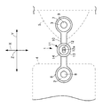
図1において、トルクロッド1は、長手方向両端に設けた弾性体2、3を介してパワーユニット4と車体5とを弾性的に連結している。パワーユニット4は自動車等の車両に搭載された内燃機関であるエンジンとトランスミッションを一体化したものであり、例えば、FF(フロントドライブ・フロントアクスル)車に横置きされている。
Hereinafter, embodiments of a dynamic damper according to the present invention will be described with reference to the drawings.
(First embodiment)
FIG. 1 and FIG. 2 are views showing a first embodiment of a dynamic damper according to the present invention.
First, the configuration will be described.
In FIG. 1, a torque rod 1 elastically connects a power unit 4 and a vehicle body 5 via elastic bodies 2 and 3 provided at both ends in the longitudinal direction. The power unit 4 is an integral part of an engine, which is an internal combustion engine mounted on a vehicle such as an automobile, and a transmission. For example, the power unit 4 is placed horizontally in an FF (front drive / front axle) vehicle.
トルクロッド1は、長手方向両端の円筒部6、7が軸部10を介して連結されているとともに、円筒部6、7の内周部が弾性体2、3を介して内筒部8、9の外周部に連結されており、この内筒部8、9が図示しないボルトによってパワーユニット4および車体5に取付けられている。
In the torque rod 1, cylindrical portions 6 and 7 at both ends in the longitudinal direction are connected via a
また、トルクロッド1は、制振対象部材を構成しており、トルクロッド1の軸部10にはダイナミックダンパ11が取付けられている。このダイナミックダンパ11は、それぞれ直交するX方向、Y方向およびZ方向の固有振動数がパワーユニット4を介してトルクロッド1に入力される共振周波数にチューニングされており、X方向、Y方向およびZ方向における特定の周波数域の振動に対して制振効果を発揮し、パワーユニット4から車体5に入力される振動を吸収するようになっている。
Further, the torque rod 1 constitutes a vibration suppression member, and a
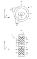
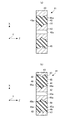
図2に示すように、ダイナミックダンパ11は、トルクロッド1に取付けられる内筒部材12と、内筒部材12の周囲に内筒部材12と同軸状に設けられた筒状の質量体であるマス部材13と、内筒部材12およびマス部材13の間に設けられ、マス部材13と内筒部材12とを弾性的に連結する弾性体としてのゴム部材14とを備えており、ゴム部材14は、内筒部材12の外周部とマス部材13の内周部に加硫接着されている。
As shown in FIG. 2, the
また、内筒部材12にはボルト穴12aが設けられており、このボルト穴12aを通してトルクロッド1にボルトを螺合することにより、マス部材13がゴム部材14を介してトルクロッド1に弾性的に連結されている。なお、図1では、ボルトを図示省略してボルト穴12aを図示している。
Further, the
一方、内筒部材12およびマス部材13の間の隙間A1、A2が第1の方向であるX方向(車両の上下方向)と第1の方向と直交する第2の方向であるY方向(車両の前後方向)とで異なる大きさとなるように、内筒部材12がX方向とY方向とで異形状に形成されている。
On the other hand, the gaps A1 and A2 between the
すなわち、内筒部材12は、隙間A1が隙間A2よりも長くなるように横長に形成されており、マス部材13は、円状に形成されている。このため、ゴム部材14は、内筒部材12を挟んでX方向の幅がY方向の幅に対して長くなっている。
That is, the
また、マス部材13の内周部には突起部15が形成されており、この突起部15は、マス部材13の周方向に延在している。また、内筒部材12の外周部には溝部16が形成されており、この溝部16は、突起部15に対向して内筒部材12の周方向に延在している。
Further, a
また、突起部15および溝部16は、X方向およびY方向と直交する第3の方向であるZ方向(車両の幅方向)に対して前後方向(Z方向)に傾斜する傾斜面15a、16aをそれぞれ有している。
The
本実施の形態では、パワーユニット4を介してトルクロッド1がX方向、Y方向およびZ方向に振動したときに、ゴム部材14を介してマス部材13が振動することにより、X方向、Y方向およびZ方向の共振周波数による振動を吸収するようになっている。
In the present embodiment, when the torque rod 1 vibrates in the X direction, Y direction, and Z direction via the power unit 4, the
すなわち、本実施の形態では、内筒部材12およびマス部材13の間の隙間がX方向とY方向とで異なる大きさとなるように、内筒部材12をX方向とY方向で異形状に形成したので、内筒部材12およびマス部材13の間の隙間A1、A2の大きさを調整することにより、内筒部材12およびマス部材13の間に介装されるゴム部材14の形状をX方向とY方向とで異なる形状にすることができる。このため、X方向とY方向とでゴム部材14の剛性を異ならせることができる。
That is, in the present embodiment, the
また、マス部材13の内周部に周方向に延在する突起部15を形成し、突起部15に、Z方向に対して前後方向に傾斜する傾斜面15aを設けたので、突起部15の傾斜面15aの傾斜角度を小さくした場合に、突起部15へのゴム部材14の当接面積を少なくしてZ方向のゴム部材14の剛性を小さくするように調整し、突起部15の傾斜面15aの傾斜角度を大きくした場合に、突起部15へのゴム部材14の当接面積を大きくしてZ方向のゴム部材14の剛性を大きくするように調整することができる。
In addition, since the protruding
このため、ゴム部材14の剛性、すなわち、固有振動数を互いに直交するX方向、Y方向およびZ方向で異ならせることができ、並進3方向の異なる共振周波数による振動の増幅を抑制することができる。
For this reason, the rigidity of the
また、本実施の形態では、単一のダイナミックダンパ11を用いて並進3方向の異なる共振周波数による振動の増幅を抑制することができるので、ダイナミックダンパ11の設置スペースやコストが増大するのを防止することができる。
Further, in the present embodiment, since a single
また、本実施の形態では、マス部材13の内周部に突起部15を設けるとともに、内筒部材12の外周部に溝部16を設け、ゴム部材14を突起部15および溝部16によって挟み込むようにしているので、ゴム部材14がZ方向に抜け出てしまうのを防止することができる。
Further, in the present embodiment, the
なお、本実施の形態では、マス部材13の内周部に突起部15を設けているが、ゴム部材14の外周部に突起部を設け、この突起部の傾斜面の傾斜角度を調整することにより、ゴム部材14の剛性を調整してもよい。
In the present embodiment, the
(第2の実施の形態)
図3は、本発明に係るダイナミックダンパの第2の実施の形態を示す図である。なお、本実施の形態では、トルクロッド1に取付けられるダイナミックダンパの構成が異なるのみであり、その他の構成は第1の実施の形態と同様である。
(Second Embodiment)
FIG. 3 is a diagram showing a second embodiment of the dynamic damper according to the present invention. In the present embodiment, only the configuration of the dynamic damper attached to the torque rod 1 is different, and the other configurations are the same as those in the first embodiment.
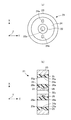
図3において、ダイナミックダンパ21は、トルクロッド1に取付けられる内筒部材22と、内筒部材22の周囲に内筒部材22と同軸状に設けられた筒状の質量体であるマス部材23と、内筒部材22およびマス部材23の間に設けられ、マス部材23と内筒部材22とを弾性的に連結する弾性体としてのゴム部材24とを備えており、ゴム部材24は、内筒部材22の外周部とマス部材23の内周部に加硫接着されている。
In FIG. 3, the
また、内筒部材22にはボルト穴22aが設けられており、このボルト穴22aを通してトルクロッド1にボルトを螺合することにより、マス部材23がゴム部材24を介してトルクロッド1に弾性的に連結されている。
Further, the
マス部材23および内筒部材22の間に設けられる弾性体としてのゴム部材24は第1の方向であるY方向(車両の前後方向)と直交する第2の方向であるX方向(車両の上下方向)に内筒部材22を挟んで対向する穴24aが形成されている。また、マス部材23および内筒部材22は、いずれも円状に形成されている。
A
また、マス部材23の内周部には突起部25が形成されており、この突起部25は、マス部材23の周方向に延在している。また、内筒部材22の外周部には溝部26が形成されており、この溝部26は、突起部25に対向して内筒部材22の周方向に延在している。
In addition, a
また、突起部25および溝部26は、X方向およびY方向と直交する第3の方向であるZ方向(車両の幅方向)に対して前後方向(Z方向)に傾斜する傾斜面25a、26aをそれぞれ有している。
The
本実施の形態では、ゴム部材24が、X方向において内筒部材22を挟んで対向する穴24aを有するので、穴24aの大きさを調整することにより、内筒部材22およびマス部材23の間に介装されるゴム部材24の剛性をX方向とY方向とで異ならせることができる。
In the present embodiment, the
また、マス部材23の内周部に周方向に延在する突起部25を形成し、突起部25、Z方向に対して前後方向に傾斜する傾斜面25aを設けたので、突起部25の傾斜面25aの傾斜角度を小さくした場合に、突起部25へのゴム部材24の当接面積を少なくしてZ方向のゴム部材24の剛性を小さくするように調整し、突起部25の傾斜面25aの傾斜角度を大きくした場合に、突起部25へのゴム部材24の当接面積を大きくしてZ方向のゴム部材24の剛性を大きくするように調整することができる。
Further, the
このため、ゴム部材24の剛性、すなわち、固有振動数を互いに直交するX方向、Y方向およびZ方向で異ならせることができ、並進3方向の異なる共振周波数による振動の増幅を抑制することができる。
For this reason, the rigidity of the
また、本実施の形態では、単一のダイナミックダンパ21を用いて並進3方向の異なる共振周波数による振動の増幅を抑制することができるので、ダイナミックダンパ21の設置スペースやコストが増大するのを防止することができる。
Further, in the present embodiment, since a single
なお、本実施の形態では、マス部材23の内周部に突起部25を設けているが、ゴム部材24の外周部に突起部を設け、この突起部の傾斜面の傾斜角度を調整することにより、ゴム部材24の剛性を調整してもよい。
In the present embodiment, the
また、ゴム部材24のX方向において内筒部材22を挟んで対向する穴24aを形成しているが、ゴム部材24のY方向において内筒部材22を挟んで対向する穴を形成してもよい。
Moreover, although the
(第3の実施の形態)
図4は、本発明に係るダイナミックダンパの第3の実施の形態を示す図である。なお、本実施の形態では、トルクロッド1に取付けられるダイナミックダンパの構成が異なるのみであり、その他の構成は第1の実施の形態と同様である。
(Third embodiment)
FIG. 4 is a diagram showing a third embodiment of a dynamic damper according to the present invention. In the present embodiment, only the configuration of the dynamic damper attached to the torque rod 1 is different, and the other configurations are the same as those in the first embodiment.
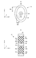
一方、内筒部材32およびマス部材33の間の隙間B1、B2が第1の方向であるX方向(車両の上下方向)と第1の方向と直交する第2の方向であるY方向(車両の前後方向)とで異なる大きさとなるように、マス部材33がX方向とY方向とで異形状に形成されている。
On the other hand, the gaps B1 and B2 between the
すなわち、マス部材33は、隙間B1が隙間B2よりも長くなるように縦長に形成されており、内筒部材32は、円状に形成されている。このため、ゴム部材34は、内筒部材32を挟んでX方向の幅がY方向の幅に対して長くなっている。
That is, the
また、マス部材33の内周部には突起部35が形成されており、この突起部35は、マス部材33の周方向に延在している。また、内筒部材32の外周部には溝部36が形成されており、この溝部36は、突起部35に対向して内筒部材32の周方向に延在している。
In addition, a
また、突起部35および溝部36は、X方向およびY方向と直交する第3の方向であるZ方向(車両の幅方向)に対して前後方向(Z方向)に傾斜する傾斜面35a、36aをそれぞれ有している。
The
本実施の形態では、内筒部材32およびマス部材33の間の隙間がX方向とY方向とで異なる大きさとなるように、マス部材33をX方向とY方向で異形状に形成したので、内筒部材32およびマス部材33の間の隙間B1、B2の大きさを調整することにより、内筒部材32およびマス部材33の間に介装されるゴム部材34の形状をX方向とY方向とで異なる形状にすることができる。このため、X方向とY方向とでゴム部材34の剛性を異ならせることができる。
In the present embodiment, the
また、マス部材33の内周部に周方向に延在する突起部35を形成し、突起部35に、Z方向に対して前後方向に傾斜する傾斜面35aを設けたので、突起部35の傾斜面35aの傾斜角度を小さくした場合に、突起部35へのゴム部材34の当接面積を少なくしてZ方向のゴム部材34の剛性を小さくするように調整し、突起部35の傾斜面35aの傾斜角度を大きくした場合に、突起部35へのゴム部材34の当接面積を大きくしてZ方向のゴム部材34の剛性を大きくするように調整することができる。
In addition, since the protruding
このため、ゴム部材34の剛性、すなわち、固有振動数を互いに直交するX方向、Y方向およびZ方向で異ならせることができ、並進3方向の異なる共振周波数による振動の増幅を抑制することができる。
For this reason, the rigidity of the
また、本実施の形態では、単一のダイナミックダンパ31を用いて並進3方向の異なる共振周波数による振動の増幅を抑制することができるので、ダイナミックダンパ31の設置スペースやコストが増大するのを防止することができる。
Further, in the present embodiment, since a single
なお、本実施の形態では、マス部材33の内周部に突起部35を設けているが、ゴム部材34の外周部に突起部を設け、この突起部の傾斜面の傾斜角度を調整することにより、ゴム部材34の剛性を調整してもよい。
In this embodiment, the
(第4の実施の形態)
図5、図6は、本発明に係るダイナミックダンパの第4の実施の形態を示す図である。なお、本実施の形態では、トルクロッド1に取付けられるダイナミックダンパの構成が異なるのみであり、その他の構成は第1の実施の形態と同様である。
(Fourth embodiment)
5 and 6 are views showing a fourth embodiment of the dynamic damper according to the present invention. In the present embodiment, only the configuration of the dynamic damper attached to the torque rod 1 is different, and the other configurations are the same as those in the first embodiment.
図5、図6において、ダイナミックダンパ41は、トルクロッド1に取付けられる内筒部材42と、内筒部材42の周囲に内筒部材42と同軸状に設けられた筒状の質量体であるマス部材43と、内筒部材42およびマス部材43の間に設けられ、マス部材43と内筒部材42とを弾性的に連結する弾性体としてのゴム部材44とを備えており、ゴム部材44は、内筒部材42の外周部とマス部材43の内周部に加硫接着されている。
5 and 6, the
また、内筒部材42にはボルト穴42aが設けられており、このボルト穴42aを通してトルクロッド1にボルトを螺合することにより、マス部材43がゴム部材44を介してトルクロッド1に弾性的に連結されている。
Further, the
一方、内筒部材42およびマス部材43の間の隙間C1、C2が第1の方向であるX方向(車両の上下方向)と第1の方向と直交する第2の方向であるY方向(車両の前後方向)とで異なる大きさとなるように、内筒部材42がX方向とY方向とで異形状に形成されている。
On the other hand, the gaps C1 and C2 between the
すなわち、内筒部材42は、隙間C1が隙間C2よりも長くなるように横長に形成されている。このため、ゴム部材44は、内筒部材42を挟んでX方向の幅がY方向の幅に対して長くなっている。
That is, the
また、マス部材43の内周部には突起部45が形成されており、この突起部45は、マス部材43の周方向に延在している。また、内筒部材42の外周部には溝部46が形成されており、この溝部46は、突起部45に対向して内筒部材42の周方向に延在している。
Further, a
また、突起部45および溝部46は、X方向およびY方向と直交する第3の方向であるZ方向(車両の幅方向)に対して前後方向(Z方向)に傾斜する傾斜面45a、46aをそれぞれ有している。また、マス部材43の肉厚は、X方向およびY方向において異なっており、マス部材43のX方向の肉厚C3がY方向の肉厚C4に対して小さくなっている。
The
また、ゴム部材44の外周部には係合部としての突起部47が設けられており、この突起部47は、ゴム部材44の周方向に等間隔で設けられている。また、マス部材43の内周部には溝部48が設けられており、この溝部48には突起部47が係合するようになっている。
Further,
突起部47は、Z方向を回転中心とした軸周りに対して溝部48に係合する傾斜面47aを有しており、溝部48は、傾斜面47aと同じ傾斜角度の傾斜面48aを有している。なお、突起部45は、マス部材43のZ方向の中央部に設けられているため、溝部48は突起部45を除いたマス部材43の内周部に設けられている。
The
本実施の形態では、パワーユニット4を介してトルクロッド1がX方向、Y方向、Z方向、X方向を回転中心とした軸周り、Y方向を回転中心とした軸周りおよびZ方向を回転中心とした軸周りに振動したときに、ゴム部材44を介してマス部材43が振動することにより、X方向、Y方向、Z方向、X方向を回転中心とした軸周り、Y方向を回転中心とした軸周りおよびZ方向を回転中心とした軸周りの共振周波数による振動を吸収するようになっている。
In the present embodiment, the torque rod 1 via the power unit 4 has an X direction, a Y direction, a Z direction, and an X axis as the rotation center, an Y axis as the rotation center and the Z direction as the rotation center. When the
すなわち、本実施の形態では、内筒部材42およびマス部材43の間の隙間がX方向とY方向とで異なる大きさとなるように、内筒部材42をX方向とY方向で異形状に形成したので、内筒部材42およびマス部材43の間の隙間C1、C2の大きさを調整することにより、内筒部材42およびマス部材43の間に介装されるゴム部材44の形状をX方向とY方向とで異なる形状にすることができる。このため、X方向とY方向とでゴム部材44の剛性、すなわち、固有振動数を異ならせることができる。
That is, in the present embodiment, the
また、マス部材43の内周部に周方向に延在する突起部45を形成し、突起部45に、Z方向に対して前後方向に傾斜する傾斜面45aを設けたので、突起部45の傾斜面45aの傾斜角度を小さくした場合に、突起部45へのゴム部材44の当接面積を少なくしてZ方向のゴム部材44の剛性を小さくするように調整し、突起部45の傾斜面45aの傾斜角度を大きくした場合に、突起部45へのゴム部材44の当接面積を大きくしてZ方向のゴム部材44の剛性を大きくするように調整することができ、ゴム部材44のZ方向の固有振動数を調整することができる。
In addition, the
また、X方向およびY方向においてマス部材43の肉厚を異ならせるようにしたので、マス部材43がX方向およびY方向を回転中心とした軸周りに回転したときの慣性モーメントを調整することができ、X方向およびY方向を回転中心として軸周りの固有振動数を異ならせることができる。
Further, since the thickness of the
また、ゴム部材44の外周部に突起部47を設け、突起部47がZ方向を回転中心とした軸周りに対してマス部材43の内周部に係合する傾斜面47aを有するので、突起部47の傾斜面47aの傾斜角度を小さくした場合に、ゴム部材44がマス部材43に当接するときの当接面積を小さくしてZ方向を回転中心とした軸周りのゴム部材44の剛性を小さくするように調整し、突起部47の傾斜面47aの傾斜角度を大きくした場合に、ゴム部材44がマス部材43に当接するときの当接面積を大きくしてZ方向を回転中心とした軸周りのゴム部材44の剛性を大きくするように調整することができる。このため、Z方向を回転中心とした軸周りの固有振動数を調整することができる。
Further, a
この結果、単一のダイナミックダンパ41を用いて並進3方向の異なる共振周波数による振動の増幅を抑制することができることに加えて、回転3方向の異なる共振周波数による振動の増幅を抑制することができ、ダイナミックダンパ41の設置スペースやコストが増大するのを防止することができる。
As a result, a single
なお、本実施の形態では、マス部材43の内周部に突起部45を設けているが、ゴム部材44の外周部に突起部を設け、この突起部の傾斜面の傾斜角度を調整することにより、ゴム部材44の剛性を調整してもよい。
In the present embodiment, the
(第5の実施の形態)
図7、図8は、本発明に係るダイナミックダンパの第5の実施の形態を示す図である。なお、本実施の形態では、トルクロッド1に取付けられるダイナミックダンパの構成が異なるのみであり、その他の構成は第1の実施の形態と同様である。
(Fifth embodiment)
7 and 8 are views showing a fifth embodiment of a dynamic damper according to the present invention. In the present embodiment, only the configuration of the dynamic damper attached to the torque rod 1 is different, and the other configurations are the same as those in the first embodiment.
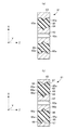
図7、図8において、ダイナミックダンパ51は、トルクロッド1に取付けられる内筒部材52と、内筒部材52の周囲に内筒部材52と同軸状に設けられた筒状の質量体であるマス部材53と、内筒部材52およびマス部材53の間に設けられ、マス部材53と内筒部材52とを弾性的に連結する弾性体としてのゴム部材54とを備えており、ゴム部材54は、内筒部材52の外周部とマス部材53の内周部に加硫接着されている。
7 and 8, the
また、内筒部材52にはボルト穴52aが設けられており、このボルト穴52aを通してトルクロッド1にボルトを螺合することにより、マス部材53がゴム部材54を介してトルクロッド1に弾性的に連結されている。
Further, the
マス部材53および内筒部材52の間に設けられる弾性体としてのゴム部材54は第1の方向であるY方向(車両の前後方向)と直交する第2の方向であるX方向(車両の上下方向)に内筒部材52を挟んで対向する穴54aが形成されている。また、内筒部材52は、円状に形成されている。
A
また、マス部材53の内周部には突起部55が形成されており、この突起部55は、マス部材53の周方向に延在している。また、内筒部材52の外周部には溝部56が形成されており、この溝部56は、突起部55に対向して内筒部材52の周方向に延在している。
Further, a
また、突起部55および溝部56は、X方向およびY方向と直交する第3の方向であるZ方向(車両の幅方向)に対して前後方向(Z方向)に傾斜する傾斜面55a、56aをそれぞれ有している。また、マス部材53の肉厚は、X方向およびY方向において異なっており、マス部材53のX方向の肉厚C3がY方向の肉厚C4に対して小さくなっている。
The
また、ゴム部材54の外周部には係合部としての突起部57が設けられており、この突起部57は、ゴム部材54の周方向に等間隔で設けられている。また、マス部材53の内周部には溝部58が設けられており、この溝部58には突起部57が係合するようになっている。
Further, the outer peripheral portion of the
突起部57は、Z方向を回転中心とした軸周りに対して溝部58に係合する傾斜面57aを有しており、溝部58は、傾斜面57aと同じ傾斜角度の傾斜面58aを有している。なお、突起部55は、マス部材53のZ方向の中央部に設けられているため、溝部58は突起部55を除いたマス部材53の内周部に設けられている。
The
本実施の形態では、ゴム部材54が、X方向において内筒部材52を挟んで対向する穴54aを有するので、穴54aの大きさを調整することにより、内筒部材52およびマス部材53の間に介装されるゴム部材54の剛性、すなわち、固有振動数をX方向とY方向とで異ならせることができる。
In the present embodiment, the
また、マス部材53の内周部に周方向に延在する突起部55を形成し、突起部55に、Z方向に対して前後方向に傾斜する傾斜面55aを設けたので、突起部55の傾斜面55aの傾斜角度を小さくした場合に、突起部55へのゴム部材54の当接面積を少なくしてZ方向のゴム部材54の剛性を小さくするように調整し、突起部55の傾斜面55aの傾斜角度を大きくした場合に、突起部55へのゴム部材54の当接面積を大きくしてZ方向のゴム部材54の剛性を大きくするように調整することができ、ゴム部材54のZ方向の固有振動数を調整することができる。
In addition, since the protruding
また、X方向およびY方向においてマス部材53の肉厚を異ならせるようにしたので、マス部材43がX方向およびY方向を回転中心とした軸周りに回転したときの慣性モーメントを調整することができ、X方向およびY方向を回転中心とした軸周りの固有振動数を異ならせることができる。
Further, since the thickness of the
また、ゴム部材54の外周部に突起部57を設け、突起部57がZ方向を回転中心とした軸周りに対してマス部材53の内周部に係合する傾斜面57aを有するので、突起部57の傾斜面57aの傾斜角度を小さくした場合に、ゴム部材54がマス部材53に当接するときの当接面積を小さくしてZ方向を回転中心とした軸周りのゴム部材54の剛性を小さくするように調整し、突起部57の傾斜面57aの傾斜角度を大きくした場合に、ゴム部材54がマス部材53に当接するときの当接面積を大きくしてZ方向を回転中心とした軸周りのゴム部材54の剛性を大きくするように調整することができる。このため、Z方向を回転中心とした軸周りの固有振動数を調整することができる。
Further, a
この結果、単一のダイナミックダンパ51を用いて並進3方向の異なる共振周波数による振動の増幅を抑制することができることに加えて、回転3方向の異なる共振周波数による振動の増幅を抑制することができ、ダイナミックダンパ51の設置スペースやコストが増大するのを防止することができる。
As a result, a single
なお、本実施の形態では、マス部材53の内周部に突起部55を設けているが、ゴム部材54の外周部に突起部を設け、この突起部の傾斜面の傾斜角度を調整することにより、ゴム部材54の剛性を調整してもよい。
In this embodiment, the
(第6の実施の形態)
図9、図10は、本発明に係るダイナミックダンパの第6の実施の形態を示す図である。なお、本実施の形態では、トルクロッド1に取付けられるダイナミックダンパの構成が異なるのみであり、その他の構成は第1の実施の形態と同様である。
(Sixth embodiment)
9 and 10 are views showing a sixth embodiment of a dynamic damper according to the present invention. In the present embodiment, only the configuration of the dynamic damper attached to the torque rod 1 is different, and the other configurations are the same as those in the first embodiment.
図9、図10は、本発明に係るダイナミックダンパの第4の実施の形態を示す図である。なお、本実施の形態では、トルクロッド1に取付けられるダイナミックダンパの構成が異なるのみであり、その他の構成は第1の実施の形態と同様である。 9 and 10 are views showing a fourth embodiment of a dynamic damper according to the present invention. In the present embodiment, only the configuration of the dynamic damper attached to the torque rod 1 is different, and the other configurations are the same as those in the first embodiment.
図9、図10において、ダイナミックダンパ61は、トルクロッド1に取付けられる内筒部材62と、内筒部材62の周囲に内筒部材62と同軸状に設けられた筒状の質量体であるマス部材63と、内筒部材62およびマス部材63の間に設けられ、マス部材63と内筒部材62とを弾性的に連結する弾性体としてのゴム部材64とを備えており、ゴム部材64は、内筒部材62の外周部とマス部材63の内周部に加硫接着されている。
9 and 10, the
また、内筒部材62にはボルト穴62aが設けられており、このボルト穴62aを通してトルクロッド1にボルトを螺合することにより、マス部材63がゴム部材64を介してトルクロッド1に弾性的に連結されている。
Further, the
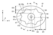
一方、内筒部材62およびマス部材63の間の隙間D1、D2が第1の方向であるX方向(車両の上下方向)と第1の方向と直交する第2の方向であるY方向(車両の前後方向)とで異なる大きさとなるように、マス部材63がX方向とY方向とで異形状に形成されている。
On the other hand, the gaps D1 and D2 between the
すなわち、マス部材63は、隙間D1が隙間D2よりも短くなるように横長に形成されており、内筒部材62は、円状に形成されている。このため、ゴム部材64は、内筒部材62を挟んでX方向の幅がY方向の幅に対して短くなっている。
That is, the
また、マス部材63の内周部には突起部65が形成されており、この突起部65は、マス部材63の周方向に延在している。また、内筒部材62の外周部には溝部66が形成されており、この溝部66は、突起部65に対向して内筒部材62の周方向に延在している。
Further, a
また、突起部65および溝部66は、X方向およびY方向と直交する第3の方向であるZ方向(車両の幅方向)に対して前後方向(Z方向)に傾斜する傾斜面65a、66aをそれぞれ有している。また、マス部材63の肉厚は、X方向およびY方向において異なっており、マス部材63のX方向の肉厚D3がY方向の肉厚D4に対して小さくなっている。
The
また、ゴム部材64の外周部には係合部としての突起部67が設けられており、この突起部67は、ゴム部材64の周方向に等間隔で設けられている。また、マス部材63の内周部には溝部68が設けられており、この溝部68には突起部67が係合するようになっている。
Further, the outer peripheral portion of the
突起部67は、Z方向を回転中心とした軸周りに対して溝部68に係合する傾斜面67aを有しており、溝部68は、傾斜面67aと同じ傾斜角度の傾斜面68aを有している。なお、突起部65は、マス部材63のZ方向の中央部に設けられているため、溝部68は突起部65を除いたマス部材63の内周部に設けられている。
The
本実施の形態では、内筒部材62およびマス部材63の間の隙間がX方向とY方向とで異なる大きさとなるように、内筒部材62をX方向とY方向で異形状に形成したので、内筒部材62およびマス部材63の間の隙間D1、D2の大きさを調整することにより、内筒部材62およびマス部材63の間に介装されるゴム部材64の形状をX方向とY方向とで異なる形状にすることができる。このため、X方向とY方向とでゴム部材64の剛性、すなわち、固有振動数を異ならせることができる。
In the present embodiment, since the
また、マス部材63の内周部に周方向に延在する突起部65を形成し、突起部65に、Z方向に対して前後方向に傾斜する傾斜面65aを設けたので、突起部65の傾斜面65aの傾斜角度を小さくした場合に、突起部65へのゴム部材64の当接面積を少なくしてZ方向のゴム部材64の剛性を小さくするように調整し、突起部65の傾斜面65aの傾斜角度を大きくした場合に、突起部65へのゴム部材64の当接面積を大きくしてZ方向のゴム部材64の剛性を大きくするように調整することができ、ゴム部材64のZ方向の固有振動数を調整することができる。
In addition, since the
また、X方向およびY方向においてマス部材63の肉厚を異ならせるようにしたので、マス部材63がX方向およびY方向を回転中心とした軸周りに回転したときの慣性モーメントを調整することができ、X方向およびY方向を回転中心とした軸周りの固有振動数を異ならせることができる。
Further, since the thickness of the
また、ゴム部材64の外周部に突起部67を設け、突起部67がZ方向を回転中心とした軸周りに対してマス部材63の内周部に係合する傾斜面67aを有するので、突起部67の傾斜面67aの傾斜角度を小さくした場合に、ゴム部材64がマス部材63に当接するときの当接面積を小さくしてZ方向を回転中心とした軸周りのゴム部材64の剛性を小さくするように調整し、突起部67の傾斜面67aの傾斜角度を大きくした場合に、ゴム部材64がマス部材63に当接するときの当接面積を大きくしてZ方向を回転中心とした軸周りのゴム部材64の剛性を大きくするように調整することができる。このため、Z方向を回転中心とした軸周りの固有振動数を調整することができる。
In addition, a
この結果、単一のダイナミックダンパ61を用いて並進3方向の異なる共振周波数による振動の増幅を抑制することができることに加えて、回転3方向の異なる共振周波数による振動の増幅を抑制することができ、ダイナミックダンパ61の設置スペースやコストが増大するのを防止することができる。
As a result, it is possible to suppress vibration amplification due to different resonance frequencies in the three translational directions using the single
なお、本実施の形態では、マス部材63の内周部に突起部65を設けているが、ゴム部材64の外周部に突起部を設け、この突起部の傾斜面の傾斜角度を調整することにより、ゴム部材64の剛性を調整してもよい。
In the present embodiment, the
なお、本実施の形態では、ダイナミックダンパを制振対象部材としてトルクロッドに適用しているが、制振対象部材としては、自動車のドライブシャフトのように少なくとも並進3方向または並進3方向と回転方向に振動するものに適用してもよい。また、ドライブシャフト等にダイナミックダンパが取付けられる場合には、内筒部材がドライブシャフトの周囲を取り囲むようにしてドライブシャフトに取付けられる。 In this embodiment, the dynamic damper is applied to the torque rod as a vibration suppression member, but as the vibration suppression member, at least three translational directions or three translational directions and a rotational direction like a drive shaft of an automobile. You may apply to what vibrates. When the dynamic damper is attached to the drive shaft or the like, the inner cylinder member is attached to the drive shaft so as to surround the drive shaft.
また、今回開示された実施の形態は、全ての点で例示であってこの実施の形態に制限されるものではない。本発明の範囲は、上記した実施の形態のみの説明ではなくて特許請求の範囲によって示され、特許請求の範囲と均等の意味および範囲内での全ての変更が含まれることが意図される。 The embodiment disclosed this time is illustrative in all respects and is not limited to this embodiment. The scope of the present invention is shown not by the above description of the embodiments but by the scope of claims for patent, and is intended to include all modifications within the meaning and scope equivalent to the scope of claims for patent.
以上のように、本発明に係るダイナミックダンパは、設置スペースやコストが増大するのを防止しつつ、並進3方向の共振周波数による振動の増幅を抑制することができるという効果を有し、制振対象部材の共振周波数による振動の増幅を抑制することができるダイナミックダンパ等として有用である。 As described above, the dynamic damper according to the present invention has an effect of suppressing vibration amplification due to the resonance frequency in the three translational directions while preventing an increase in installation space and cost. This is useful as a dynamic damper or the like that can suppress the amplification of vibration due to the resonance frequency of the target member.
1 トルクロッド(制振対象部材)
11、21、31、41、51、61 ダイナミックダンパ
12、22、32、42、52、62 内筒部材
13、23、33、43、53、63 マス部材(質量体)
14、24、34、44、54、64 ゴム部材(弾性体)
15、25、35、45、55、65 突起部
24a、54a 穴
47、57、67 突起部(係合部)
1 Torque rod (member for vibration control)
11, 21, 31, 41, 51, 61
14, 24, 34, 44, 54, 64 Rubber member (elastic body)
15, 25, 35, 45, 55, 65
Claims (3)
前記内筒部材および前記質量体の間の隙間が第1の方向と前記第1の方向と直交する第2の方向とで異なる大きさとなるように、前記内筒部材または質量体を前記第1の方向と前記第2の方向で異形状に形成し、
前記質量体の内周部または前記弾性体の外周部のいずれか一方に、前記質量体の内周部または前記弾性体の外周部のいずれか他方に係合する突起部を形成し、前記突起部が、前記第1の方向および前記第2の方向と直交する第3の方向に対して前後方向に傾斜する傾斜面を有することを特徴とするダイナミックダンパ。 Provided between the inner cylinder member and the mass body, an inner cylinder member attached to the vibration suppression target member, a cylindrical mass body provided coaxially with the inner cylinder member around the inner cylinder member In a dynamic damper comprising an elastic body that elastically connects the mass body and the inner cylinder member,
The inner cylinder member or the mass body is the first cylinder and the mass body so that the gap between the inner cylinder member and the mass body is different in a first direction and a second direction orthogonal to the first direction. And a different shape in the second direction,
A protrusion that engages either the inner periphery of the mass body or the outer periphery of the elastic body is formed on either the inner periphery of the mass body or the outer periphery of the elastic body, and the protrusion The dynamic damper is characterized in that the portion has an inclined surface that inclines in the front-rear direction with respect to the first direction and a third direction orthogonal to the second direction.
前記弾性体は、第1の方向と直交する第2の方向に前記内筒部材を挟んで対向する穴を有し、
前記質量体の内周部または前記弾性体の外周部のいずれか一方に、前記質量体の内周部または前記弾性体の外周部のいずれか他方に係合する突起部を形成し、前記突起部が、前記第1の方向および前記第2の方向と直交する第3の方向に対して前後方向に傾斜する傾斜面を有することを特徴とするダイナミックダンパ。 Provided between the inner cylinder member and the mass body, an inner cylinder member attached to the vibration suppression target member, a cylindrical mass body provided coaxially with the inner cylinder member around the inner cylinder member In a dynamic damper comprising an elastic body that elastically connects the mass body and the inner cylinder member,
The elastic body has a hole facing the inner cylinder member in a second direction orthogonal to the first direction,
A protrusion that engages either the inner periphery of the mass body or the outer periphery of the elastic body is formed on either the inner periphery of the mass body or the outer periphery of the elastic body, and the protrusion The dynamic damper is characterized in that the portion has an inclined surface that inclines in the front-rear direction with respect to the first direction and a third direction orthogonal to the second direction.
Priority Applications (1)
| Application Number | Priority Date | Filing Date | Title |
|---|---|---|---|
| JP2008220008A JP4867960B2 (en) | 2008-08-28 | 2008-08-28 | Dynamic damper |
Applications Claiming Priority (1)
| Application Number | Priority Date | Filing Date | Title |
|---|---|---|---|
| JP2008220008A JP4867960B2 (en) | 2008-08-28 | 2008-08-28 | Dynamic damper |
Publications (2)
| Publication Number | Publication Date |
|---|---|
| JP2010053966A true JP2010053966A (en) | 2010-03-11 |
| JP4867960B2 JP4867960B2 (en) | 2012-02-01 |
Family
ID=42070117
Family Applications (1)
| Application Number | Title | Priority Date | Filing Date |
|---|---|---|---|
| JP2008220008A Expired - Fee Related JP4867960B2 (en) | 2008-08-28 | 2008-08-28 | Dynamic damper |
Country Status (1)
| Country | Link |
|---|---|
| JP (1) | JP4867960B2 (en) |
Cited By (2)
| Publication number | Priority date | Publication date | Assignee | Title |
|---|---|---|---|---|
| JP2013112042A (en) * | 2011-11-25 | 2013-06-10 | Toyota Motor Corp | Vehicle torque rod and power unit supporting structure |
| JP2014218352A (en) * | 2013-05-10 | 2014-11-20 | 三菱電機株式会社 | Vibration control structure and vibration control method for elevator hoisting machine, and dynamic vibration absorber for elevator hoisting machine |
Citations (4)
| Publication number | Priority date | Publication date | Assignee | Title |
|---|---|---|---|---|
| JPS5894936A (en) * | 1981-12-01 | 1983-06-06 | Olympus Optical Co Ltd | Method of processing anti-reflex surface of plastic lens as aventurine |
| JPS61161009A (en) * | 1985-01-08 | 1986-07-21 | Mitsubishi Electric Corp | Mos differential amplifier |
| JPH0230553A (en) * | 1988-07-21 | 1990-01-31 | Matsushita Electric Ind Co Ltd | Thick-film thermal head |
| JPH0389036A (en) * | 1989-08-31 | 1991-04-15 | Toyoda Gosei Co Ltd | Fixing method of vibration isolating bushing |
-
2008
- 2008-08-28 JP JP2008220008A patent/JP4867960B2/en not_active Expired - Fee Related
Patent Citations (4)
| Publication number | Priority date | Publication date | Assignee | Title |
|---|---|---|---|---|
| JPS5894936A (en) * | 1981-12-01 | 1983-06-06 | Olympus Optical Co Ltd | Method of processing anti-reflex surface of plastic lens as aventurine |
| JPS61161009A (en) * | 1985-01-08 | 1986-07-21 | Mitsubishi Electric Corp | Mos differential amplifier |
| JPH0230553A (en) * | 1988-07-21 | 1990-01-31 | Matsushita Electric Ind Co Ltd | Thick-film thermal head |
| JPH0389036A (en) * | 1989-08-31 | 1991-04-15 | Toyoda Gosei Co Ltd | Fixing method of vibration isolating bushing |
Cited By (2)
| Publication number | Priority date | Publication date | Assignee | Title |
|---|---|---|---|---|
| JP2013112042A (en) * | 2011-11-25 | 2013-06-10 | Toyota Motor Corp | Vehicle torque rod and power unit supporting structure |
| JP2014218352A (en) * | 2013-05-10 | 2014-11-20 | 三菱電機株式会社 | Vibration control structure and vibration control method for elevator hoisting machine, and dynamic vibration absorber for elevator hoisting machine |
Also Published As
| Publication number | Publication date |
|---|---|
| JP4867960B2 (en) | 2012-02-01 |
Similar Documents
| Publication | Publication Date | Title |
|---|---|---|
| EP2345827B1 (en) | Anti-Vibration Device | |
| WO2014030748A1 (en) | Vibration isolation device | |
| WO2017026330A1 (en) | Engine device support structure and engine device installation method | |
| US9353825B2 (en) | Vibration absorbing apparatus | |
| JP2020034126A (en) | Stopper and vibration control unit | |
| WO2010137585A1 (en) | Antivibration device | |
| JP4867960B2 (en) | Dynamic damper | |
| JP5264400B2 (en) | Vibration isolator | |
| JP2017101737A (en) | Vibration controller | |
| JP2008030500A (en) | Vibration isolator | |
| KR20150106638A (en) | Dynamic damper | |
| JP2007064353A (en) | Swing damping device | |
| JP5693386B2 (en) | Vibration isolator | |
| JP4543318B2 (en) | Dynamic damper | |
| JP2009085315A (en) | Cylindrical type antivibration device | |
| JP6182077B2 (en) | Cylindrical vibration isolator | |
| JP5230520B2 (en) | Vibration isolator | |
| KR102289833B1 (en) | Dynamic damper for hollow drive shaft | |
| KR102496692B1 (en) | Dynamic damper | |
| JP4533606B2 (en) | Anti-vibration mounting device | |
| JP2009275746A (en) | Torque rod | |
| JP2008002677A (en) | Cylindrical dynamic damper | |
| JPH02117472A (en) | Body mount construction in front frame | |
| JP2006312983A (en) | Dynamic damper | |
| JP2016160983A (en) | Vibration absorber |
Legal Events
| Date | Code | Title | Description |
|---|---|---|---|
| A621 | Written request for application examination |
Free format text: JAPANESE INTERMEDIATE CODE: A621 Effective date: 20101118 |
|
| TRDD | Decision of grant or rejection written | ||
| A977 | Report on retrieval |
Free format text: JAPANESE INTERMEDIATE CODE: A971007 Effective date: 20111013 |
|
| A01 | Written decision to grant a patent or to grant a registration (utility model) |
Free format text: JAPANESE INTERMEDIATE CODE: A01 Effective date: 20111018 |
|
| A01 | Written decision to grant a patent or to grant a registration (utility model) |
Free format text: JAPANESE INTERMEDIATE CODE: A01 |
|
| A61 | First payment of annual fees (during grant procedure) |
Free format text: JAPANESE INTERMEDIATE CODE: A61 Effective date: 20111031 |
|
| FPAY | Renewal fee payment (prs date is renewal date of database) |
Free format text: PAYMENT UNTIL: 20141125 Year of fee payment: 3 |
|
| LAPS | Cancellation because of no payment of annual fees |