JP2010051857A - Crusher and crushed powder ingression prevention structure - Google Patents
Crusher and crushed powder ingression prevention structure Download PDFInfo
- Publication number
- JP2010051857A JP2010051857A JP2008217235A JP2008217235A JP2010051857A JP 2010051857 A JP2010051857 A JP 2010051857A JP 2008217235 A JP2008217235 A JP 2008217235A JP 2008217235 A JP2008217235 A JP 2008217235A JP 2010051857 A JP2010051857 A JP 2010051857A
- Authority
- JP
- Japan
- Prior art keywords
- peripheral surface
- seal ring
- side plate
- hole
- pulverized powder
- Prior art date
- Legal status (The legal status is an assumption and is not a legal conclusion. Google has not performed a legal analysis and makes no representation as to the accuracy of the status listed.)
- Granted
Links
Images

Abstract
Description
本発明は、プラスチック材などを粉砕する粉砕装置(ないし破砕装置)と、その軸受け部への粉砕粉の進入を防止するための粉砕粉進入防止構造に関するものである。 The present invention relates to a crushing device (or crushing device) for crushing a plastic material and the like and a pulverized powder intrusion prevention structure for preventing the pulverized powder from entering a bearing portion thereof.
プラスチック製品の成形時には、金型に溶融した樹脂材料を注入するための経路も固化して取り出され、製品と切り離される。この経路の部分が固化したものはスプル・ランナーと呼ばれ、粉砕装置などで粉砕した後、バージンペレットに混入されてリサイクル材として再利用される。粉砕装置で粉砕されたものは粉砕材と呼ばれる。このような粉砕装置の多くは、例えば、下記特許文献1に示すように、粉砕槽を形成する本体ケーシングと、前記粉砕槽内に略水平かつ回転可能に支持されており表面に粉砕刃が形成された回転軸と、該回転軸を支持する軸受けと、前記粉砕刃が通過可能な切り欠き刃部が形成された固定刃と、粉砕対象物の落下を防止するガイドプレートを備えており、前記粉砕刃が固定刃を通過する際に、粉砕対象物の粉砕が行われる。
ところで、粉砕対象物を粉砕した際には、粉砕刃のサイズにより所定の大きさにカットされた粒のほかに、小さな切片や粉状の粉砕粉が必ず発生する。近年は特に、ガラス繊維等を含んだ樹脂材料が数多く存在しており、これらの材料が粉砕粉として軸受け部に進入すると、短期間で摩耗を起こすなど、種々の不具合要因となる。そのため、発生した粉砕粉から軸受けを保護するために、粉砕刃と軸受けの間に、側面板あるいは、側面板とシールリングが設けられている。図5(A)に示す例では、表面に粉砕刃20が設けられた回転軸18の端部は、本体ケーシングの側面12Aに設けられた貫通孔16Aを貫通し、軸受け30Aによって支持されており、該軸受け30Aと粉砕刃20の端面20Aの間に鍔部202と筒部204からなる側面板200が設けられている。また、図5(B)に示す例では、鍔部212と、段部216を有する筒部214からなる側面板210に加えて、シールリング220が設けられている。
By the way, when the object to be pulverized is pulverized, small slices and powdered pulverized powder are always generated in addition to the grains cut into a predetermined size depending on the size of the pulverizing blade. In recent years, there are many resin materials containing glass fibers and the like, and when these materials enter the bearing portion as pulverized powder, they cause various problems such as wear in a short period of time. Therefore, in order to protect the bearing from the generated pulverized powder, a side plate or a side plate and a seal ring are provided between the pulverizing blade and the bearing. In the example shown in FIG. 5 (A), the end portion of the
しかしながら、以上のように側面板200あるいは、側面板210とシールリング220を利用した技術では、前記側面板200,210とシールリング220は、前記貫通孔16Aの内部に位置しており、いずれも粉砕刃20(回転軸18)とともに回転する構造になっている。このため、前記貫通孔16Aの内周面と側面板200、あるいは、側面板210とシールリング220の外周面には隙間(クリアランス)Sが必要になり、粉砕粉が軸受け30A側に進入するのを完全に防止することができないという不都合がある。前記軸受け30A側に進入した粉砕粉は、軸受け破損の要因となるばかりでなく、それまでとは材質や色が異なる粉砕対象物の粉砕処理を行った際に、粉砕槽内へ逆流し、成形不良の要因となる場合もある。
However, in the technique using the
本発明は、以上の点に着目したもので、その目的は、粉砕時に発生する粉砕粉が軸受け側へ進入するのを防止することができる粉砕装置及びその粉砕粉進入防止構造を提供することである。 The present invention focuses on the above points, and its purpose is to provide a pulverizing apparatus capable of preventing the pulverized powder generated during pulverization from entering the bearing and a pulverized powder intrusion preventing structure thereof. is there.
前記目的を達成するため、本発明は、端部を除く表面に粉砕刃が形成され、前記端部が粉砕槽を形成する本体ケーシングの貫通孔を貫通する回転軸が、前記粉砕槽内に略水平かつ回転可能となるように、前記端部が軸受けによって支持される粉砕装置の粉砕粉進入防止構造であって、前記粉砕刃と軸受けの間に位置するように前記回転軸の外周面に装着される筒部と、一方の主面が前記粉砕刃の軸方向端面のほぼ全面に密着する鍔部を有しており、前記回転軸とともに回転する側面板,該側面板の鍔部の他方の主面と前記本体ケーシングの貫通孔の内周面の双方に密着し、前記回転軸とともに回転しない略リング状のシール体,該シール体が回転軸とともに回転するのを防止するための回り止め手段,を備えたことを特徴とする。 In order to achieve the above-mentioned object, the present invention provides a grinding blade formed on the surface excluding the end portion, and a rotary shaft penetrating through a through hole of a main body casing in which the end portion forms a crushing tank. The crushed powder intrusion preventing structure of the pulverizing apparatus, in which the end is supported by a bearing so as to be horizontal and rotatable, is mounted on the outer peripheral surface of the rotating shaft so as to be positioned between the pulverizing blade and the bearing And a side surface plate that rotates together with the rotating shaft and the other side of the flange portion of the side surface plate. A substantially ring-shaped seal body that is in close contact with both the main surface and the inner peripheral surface of the through hole of the main body casing and does not rotate with the rotating shaft, and a detent means for preventing the seal body from rotating with the rotating shaft , Provided.
主要な形態の一つは、前記回転軸の軸方向に荷重を付加する弾性体の利用によって、前記シール体を前記側面板の鍔部に密着させることを特徴とする。他の形態は、前記シール体の内周面と前記側面板の筒部の間と、前記側面板の鍔部の外周面と前記本体ケーシングの貫通孔の内周面の間に、隙間を設けたことを特徴とする。 One of the main forms is characterized in that the seal body is brought into close contact with the flange portion of the side plate by using an elastic body that applies a load in the axial direction of the rotating shaft. In another embodiment, a gap is provided between the inner peripheral surface of the seal body and the cylindrical portion of the side plate, and between the outer peripheral surface of the flange portion of the side plate and the inner peripheral surface of the through hole of the main body casing. It is characterized by that.
更に他の形態は、前記シール体が、樹脂製であることを特徴とする。更に他の形態は、前記シール体が熱膨張性を有しており、熱膨張によって径方向に広がることによって、該シール体の外周面と前記本体ケーシングの貫通孔の内周面を密着させることを特徴とする。あるいは、前記シール体の外径部を径方向に押し広げる機構を設けることによって、該シール体の外周面と前記本体ケーシングの貫通孔の内周面を密着させることを特徴とする。 Yet another embodiment is characterized in that the sealing body is made of resin. In still another embodiment, the seal body has a thermal expansion property, and the outer peripheral surface of the seal body and the inner peripheral surface of the through hole of the main body casing are brought into close contact with each other by spreading in the radial direction due to thermal expansion. It is characterized by. Alternatively, by providing a mechanism for expanding the outer diameter portion of the seal body in the radial direction, the outer peripheral surface of the seal body and the inner peripheral surface of the through hole of the main body casing are brought into close contact with each other.
本発明の粉砕装置は、前記いずれかに記載の粉砕粉進入防止構造を備えたことを特徴とする。本発明の前記及び他の目的,特徴,利点は、以下の詳細な説明及び添付図面から明瞭になろう。 A pulverizing apparatus according to the present invention includes the pulverized powder intrusion prevention structure according to any one of the above. The above and other objects, features and advantages of the present invention will become apparent from the following detailed description and the accompanying drawings.
本発明は、粉砕粉の進入を抑制し回転軸とともに回転する側面板と、該側面板と本体ケーシングの貫通孔内周面に密着し粉砕粉の進入を防止するとともに、回り止め手段によって前記回転軸とともに回転しないシール体を、前記回転軸の表面の粉砕刃と軸受けの間に設けることとした。このため、前記側面板がシール体を保護して粉砕粉の進入を抑制し、前記シール体が回転軸の軸方向及び径方向の隙間を塞ぐため、前記粉砕刃側から軸受け側への粉砕粉の進入を完全に防止できるという効果が得られる。 The present invention suppresses the ingress of pulverized powder and rotates together with a rotating shaft, and prevents the pulverized powder from entering by adhering to the side surface plate and the inner peripheral surface of the through hole of the main body casing. A seal body that does not rotate with the shaft is provided between the grinding blade on the surface of the rotating shaft and the bearing. For this reason, the side plate protects the sealing body and suppresses the entry of pulverized powder, and the sealing body closes the axial and radial gaps of the rotating shaft, so that the pulverized powder from the pulverizing blade side to the bearing side The effect of completely preventing the entry of can be obtained.
以下、本発明を実施するための最良の形態を、実施例に基づいて詳細に説明する。 Hereinafter, the best mode for carrying out the present invention will be described in detail based on examples.
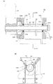
最初に、図1〜図3を参照しながら本発明の実施例1を説明する。図1は、本実施例の粉砕装置を示す図であり、(A)は主要部を回転軸に沿って切断し、全体を上方から見た平面図,(B)は前記(A)を#A−#A線に沿って切断し矢印方向に見た断面図である。図2は、粉砕粉進入防止構造を拡大して示す断面図、図3は、前記粉砕粉進入防止構造の分解斜視図である。
First,
まず、図1を参照して、粉砕装置10の構成を説明する。粉砕装置10は、本体ケーシング12によって粉砕槽14が形成されており、前記本体ケーシング12の対向する側面12A,12Bの間には、前記粉砕槽14内において略水平かつ回転可能となるように、粉砕刃20と爪22を表面に備えた回転軸18が設けられている。該回転軸18は、前記粉砕刃20が形成されていない両端部が前記側面12A,12Bに設けられた貫通孔16A,16Bを貫通し、本体ケーシング12に固定された一対の軸受け30A,30Bによって回転可能に支持されている。前記回転軸18は、本体ケーシング12の外側に設けられた減速機24の回転が伝達されることによって回転可能となっている。
First, the configuration of the
前記粉砕槽14内には、前記粉砕刃20を挟んで対向する位置に、前記粉砕刃20と爪22が通過可能な切り欠き刃部(図示せず)が形成された固定刃26と、粉砕処理前の粉砕対象物が下方に落下することを防止するためのガイドプレート28が、傾斜面を形成するように固定されており、前記粉砕刃20が固定刃26を通過する際に、前記粉砕対象物の粉砕が行われる。本実施例では、このような粉砕装置10において、前記粉砕刃20の軸方向端面20Aと前記軸受け30A,30Bの間に、粉砕粉進入防止構造50A,50Bが設けられている。
In the crushing
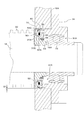
前記粉砕粉進入防止構造50A,50Bについて、図2及び図3も参照して詳細に説明する。なお、図2及び図3は、一方の粉砕粉進入防止構造50Aについて図示したものであるが、他方の粉砕粉進入防止構造50Bについても、同様の構造となっている。粉砕粉進入防止構造50Aは、側面板52,シールリング70,シールサポート80,Oリング90,シールリング押さえ92と、前記軸受け30Aに設けられた回り止めピン38によって構成されている。前記軸受け30Aは、貫通孔34を備えた軸受け本体32と軸受けケーシング36によって構成されており、前記軸受けケーシング36の筒部36Aの端面に、前記回り止めピン38が適宜間隔で複数(図示の例では2つ)設けられている。
The pulverized powder
まず、前記側面板52は、前記回転軸18の外周面に装着されるものであって、鍔部54と筒部56と貫通孔60を備えており、例えば、金属によって形成されている。前記貫通孔60には、前記回転軸18の外周面に設けられた凸状のキー18Aと嵌合可能なキー溝62が形成されており、該キー溝62と前記キー18Aの嵌合によって、前記側面板52が前記回転軸18とともに回転可能となっている。前記鍔部54は、一方の主面54Aが、前記粉砕刃20の端面20Aと密着可能であり、その外周面54Cは、本体ケーシング側面12Aの貫通孔16Aの内周面との間に回転摩擦抵抗を低減するための隙間(クリアランス)S1を形成するような寸法に形成されている。金属製の側面板52と金属製の本体ケーシング12が接触すると、金属粉が発生して製品に混入するおそれがあるが、前記隙間S1を設けることにより、このような不具合を防止することができる。また、前記筒部56には段部58が設けられており、該段部58には、後述するシールリング押さえ92を締め込むためのネジ98が螺合するネジ穴64が適宜間隔で複数形成されている。
First, the
シールリング70は、前記粉砕刃20側から軸受け30A側への粉砕粉の進入を防止するためのものであって、貫通孔72と段部74を有する略リング状に形成されており、前記側面板鍔部54の主面54Bと、前記貫通孔16Aの内周面の双方に密着可能となっている。該シールリング70の内周面70Bは、前記側面板52の筒部56の外周面との間に、隙間S2(図2参照)を形成する寸法に設定されている。該隙間S2は、回転摩擦抵抗を低減するとともに、過度の熱膨張を回避するためのものである。また、該シールリング70の軸受け30A側の主面には、前記回り止めピン38を受ける凹部76(図示の例では2か所)が設けられている。このようなシールリング70としては、例えば樹脂が利用され、本実施例では、特に熱膨張性を有する樹脂を利用することによって、前記貫通孔16Aの内周面との密着を図っている。
The
シールサポート80は、鍔部82と筒部84と貫通孔86を備えており、前記筒部84の外周面にOリング90が装着され、前記シールリング70と重ねたときに、該シールリング70の段部74とシールサポート80の鍔部82の間に、前記Oリング90が挟まれるようになっている。また、前記鍔部82には、前記シールリング70の凹部76と対応する位置に、前記回り止めピン38が貫通可能な穴88が形成されている。前記シールリング押さえ92は、前記シールサポート80の鍔部82と接触可能な略リング状であって、貫通孔94を備えるとともに、前記シールリング70を前記シールサポート80を介して前記側面板52に対して締め込むためのネジ98と螺合する複数のネジ穴96が適宜位置に設けられている。前記シールサポート80を形成する材料としては、例えば樹脂が利用される。また、本実施例では、前記シールリング70を側面板52に密着させるための弾性体として前記Oリング90を利用しているが、他の公知のゴムやウェーブワッシャなどの弾性体を利用するようにしてもよい。前記シールリング押さえ92としては、例えば、金属などが利用される。
The
次に、本実施例の作用を説明する。上述した各部は、例えば、まず、前記側面板52の鍔部主面54B側にシールリング70を嵌め、次いで、筒部84にOリング90を装着したシールサポート80を、前記シールリング70に重ねるように嵌める。次に、前記シールリング押さえ92を前記側面板52の段部58に乗せ、該段部58のネジ穴64とシールリング押さえ92のネジ穴96の位置を合わせてネジ98を螺合し、前記Oリング90の弾性力を利用して前記シールリング70を側面板52の鍔部主面54Bに密着させる。以上のようにして組み立てた側面板52,シールリング70,シールサポート80,Oリング90,シールリング押さえ92は、前記側面板52のキー溝62と回転軸18のキー18Aの位置が合うように回転軸18の端部に装着される。そして、シールリング70の凹部76及びシールサポート80の穴88に、前記回り止めピン38を挿入して軸受け30Aを装着する。他方の粉砕粉進入防止構造50Bも同様にして組み立てられる。
Next, the operation of this embodiment will be described. In each of the above-described parts, for example, first, the
以上のようにして組み立てた粉砕粉進入防止構造50A,50Bを取り付けた粉砕装置10では、前記シールリング押さえ92をネジ98で締め込んでOリング90を潰すため、回転軸18の軸方向への荷重が前記シールリング70に加わり、該シールリング70を側面板52の鍔部主面54Bに持続的に密着させることができる。また、シールリング70とシールサポート80が樹脂製であって、軸受けケーシング36の回り止めピン38によって回転しないように固定されているため、前記側面板52に密着したシールリング70には、回転摩擦によって摩擦熱が生じる。金属に比べ熱による膨張率が大きい樹脂製のシールリング70が、この摩擦熱によって膨張するため、本体ケーシング12の貫通孔16Aの内周面と前記シールリング70の外周面70Aに、部品相互の加工精度により隙間が発生したとしても、熱膨張によってその隙間を完全に塞ぎ、粉砕粉の進入を防止する。なお、シールリング70の内周面70B及びシールサポート80の内周面80Aと、側面板筒部56の外周面の間に隙間S2を設けるとともに、側面板鍔部54の外周面54Cと前記貫通孔16Aの内周面の間に隙間S1を設けているため、回転摩擦抵抗を低減するとともに、過度の熱膨張が回避される。
In the pulverizing
このように、実施例1によれば、次のような効果がある。
(1)粉砕粉の進入を抑制し回転軸18とともに回転する側面板52と、該側面板52と本体ケーシング12の貫通孔16A,16Bの内周面に密着し粉砕粉の進入を防止するとともに、回り止めピン38によって前記回転軸18とともに回転しないシールリング70を、粉砕刃20と軸受け30A及び30Bの間に設けることとした。このため、前記側面板52がシールリング70を保護して粉砕粉の進入を抑制し、前記シールリング70が回転軸18の軸方向及び径方向の隙間を塞ぐために、前記粉砕刃20側から軸受け30A,30B側への粉砕粉の進入を完全に防止できる。
Thus, according to the first embodiment, there are the following effects.
(1) The
(2)軸方向に荷重を加えることができるOリング90を設けることとしたので、側面板52との回転摩擦によって前記シールリング70が摩耗したとしても、密着状態を持続させることができる。
(3)側面板52の鍔部外周面54Cと貫通孔16Aの内周面の間に隙間S1と設けるとともに、シールリング70及びシールサポート80の内周面と側面板52の筒部56の外周面との間に隙間S2を設けることとしたので、回転摩擦抵抗の低減を図ることができる。
(4)前記シールリング70が摩擦熱によって熱膨張する特性を利用して、前記貫通孔16A及び16Bの内周面とシールリング70の外周面70Aを密着させることとしたので、部品相互の加工精度による隙間が生じたとしても、該隙間を塞いで粉砕粉の進入を防止できる。
(2) Since the O-
(3) A clearance S1 is provided between the flange outer
(4) Since the
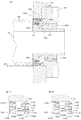
次に、図4を参照しながら本発明の実施例2を説明する。なお、上述した実施例1と同一ないし対応する構成要素には、同一の符号を用いることとする。図4(A)は、本実施例の粉砕粉進入防止構造を拡大して示す断面図,図4(B-1)及び(B-2)は、シールリングと本体ケーシング側の密着機構を示す断面拡大図である。上述した実施例では、シールリング70の熱膨張性を利用して、本体ケーシングの貫通孔内周面との密着を図ることとしたが、本実施例は、前記シールリングの外周部を径方向に広げる機構を設けた例である。
Next,
本実施例の粉砕粉進入防止構造100は、側面板52,シールリング102,シールリング押さえ110,回り止めピン116及び120と、スプリング122によって構成されている。前記側面板52の構成は、前記実施例1と同様である。前記シールリング102は、略リング状であって、一方の主面102Aが前記側面板52の鍔部主面54Bに密着し、他方の主面102Bの外周側には、図4(B-1)に示すテーパ状の溝104が形成され、内周側には、凹部106が複数形成されている。このようなシールリング102は、前記実施例1と同様に、樹脂によって形成されている。
The pulverized powder
次に、シールリング押さえ110は、樹脂や金属などによって略リング状に形成されており、一方の主面110Aの外周側には、前記シールリング102の溝104に挿入されるテーパ状の凸面112が設けられている。該凸面112は、図4(B-1)に示すように、前記シールリング102の溝104よりもテーパが大きく形成されており、該凸面112を前記溝104に嵌め込むことによって、前記シールリング102の外周面102Cを押し広げ、回転していない状態においても本体ケーシング12の貫通孔16Aの内周面との隙間を塞ぐことが可能となっている。また、前記シールリング押さえ110の内周側には、前記シールリング102の凹部106に嵌合する回り止めピン116が貫通する貫通孔114が設けられている。
Next, the
更に、前記シールリング押さえ110の他方の主面110Bの外周側には、軸受けケーシング36の筒部36Aに固定された回り止めピン120が嵌合する凹部118が形成されている。なお、前記回り止めピン120の外周面にはスプリング122が取り付けられており、該スプリング122が前記シールリング押さえ110の主面110Bに接触することによって、軸方向への荷重が該シールリング押さえ110を介して前記シールリング102に伝わり、該シールリング102を側面板52に対して持続的に密着させることができる。同時に、前記シールリング102に形成された溝104に、シールリング押さえ110の凸面112が挿入されることにより、シールリング102の外周部が図4(B-1)に破線で示すように押し広げられ、本体ケーシング12の貫通孔16Aの内周面と、シールリング102の外周面102Cの隙間を完全に塞ぐことができる。これにより、前記貫通孔16Aの内周面とシールリング外周面102Cに、部品相互の加工精度による隙間が発生したとしても、隙間を完全になくすことが可能となる。
Further, on the outer peripheral side of the other
このように、実施例2によれば、軸受けケーシング36の回り止めピン120に取り付けたスプリング122によって、シールリング押さえ110を介してシールリング102を側面板52に密着させる。これと同時に、前記シールリング押さえ110に設けた凸面112をシールリング102に設けた溝104に挿入して押し広げることで、シールリング外周面102Cと貫通口16Aの内周面の隙間も塞ぐことができるため、上述した実施例1と同様の効果が得られる。なお、本実施例においても、側面板52の鍔部外周面54Cと貫通孔16Aの内周面の間に隙間S1を設けるとともに、シールリング102の内周面102D及びシールリング押さえ110の内周面111と側面板筒部56の外周面の間に隙間S2を設け、回転摩擦抵抗の低減と過度の熱膨張を抑制することは、上述した実施例1と同様である。
Thus, according to the second embodiment, the
なお、本発明は、上述した実施例に限定されるものではなく、本発明の要旨を逸脱しない範囲内において種々変更を加え得ることができる。例えば、以下のものも含まれる。
(1)前記実施例に示した各部の形状・大きさは一例であり、必要に応じて適宜変更可能である。
(2)前記実施例に示した粉砕装置10の構成も一例であり、本発明の粉砕粉進入防止構造を備えたものであれば、必要に応じて適宜設計変更してよい。
(3)実施例1で示したOリング90や実施例2で示したスプリング122も一例であり、側面板52に軸方向に荷重を付加することができるものであれば、他の公知の各種の弾性体を利用してよい。
In addition, this invention is not limited to the Example mentioned above, A various change can be added in the range which does not deviate from the summary of this invention. For example, the following are also included.
(1) The shape and size of each part shown in the above-described embodiment is an example, and can be appropriately changed as necessary.
(2) The configuration of the pulverizing
(3) The O-
(4)上述した組み立て手順も一例であり、同様の効果を奏するように適宜変更してよい。 (4) The above-described assembly procedure is also an example, and may be changed as appropriate to achieve the same effect.
(5)前記実施例1におけるシールリング押さえ92の締め込み方法も一例であり、該シールリング押さえ92の内径側と側面板52の筒部56の外周面にネジ部を設け、前記シールリング押さえ92を回転させて締め込むようにするなど、同様の効果を奏するように適宜変更してよい。
(6)実施例2では、シールリング102の溝104とシールリング押さえ110の凸面112のテーパの大きさの差によってシールリング102の外周部を押し広げることとしたが、これも一例であり、図4(B-2)に示すように、シールリング102にテーパのない溝104Aを設け、該溝104Aにテーパ状の凸面112を挿入するなど、同様の効果を奏するように適宜設計変更してよい。
(5) The method of tightening the
(6) In Example 2, the outer peripheral portion of the
本発明によれば、粉砕粉の進入を抑制し回転軸とともに回転する側面板と、該側面板と本体ケーシングの貫通孔内周面に密着し粉砕粉の進入を防止するとともに、回り止め手段によって前記回転軸とともに回転しないシール体を、前記回転軸の表面の粉砕刃の端面と軸受けの間に設けることとした。このため、粉砕刃側から軸受け側への粉砕粉の進入を防止するための粉砕粉進入防止構造の用途に適用できる。特に、プラスチック材などを粉砕するための粉砕装置用の粉砕粉進入防止構造の用途として好適である。 According to the present invention, the side plate that suppresses the intrusion of the pulverized powder and rotates together with the rotating shaft, the side surface plate and the through hole of the main body casing are in close contact with each other to prevent the pulverized powder from entering, and the rotation preventing means. The sealing body that does not rotate with the rotating shaft is provided between the end face of the grinding blade on the surface of the rotating shaft and the bearing. For this reason, it is applicable to the use of the pulverized powder intrusion prevention structure for preventing the pulverized powder from entering the bearing side from the pulverizing blade side. In particular, it is suitable as an application of a pulverized powder intrusion prevention structure for a pulverizer for pulverizing plastic materials and the like.
10:粉砕装置
12:本体ケーシング
12A,12B:側面
14:粉砕槽
16A,16B:貫通孔
18:回転軸
18A:キー
20:粉砕刃
20A:端面
22:爪
24:減速機
26:固定刃
28:ガイドプレート
30A,30B:軸受け
32:軸受け本体
34:貫通孔
36:軸受けケーシング
36A:筒部
38:回り止めピン
50A,50B:粉砕粉進入防止構造
52:側面板
54:鍔部
54A,54B:主面
54C:外周面
56:筒部
58:段部
60:貫通孔
62:キー溝
64:ネジ穴
70:シールリング
70A:外周面
70B:内周面
72:貫通孔
74:段部
76:凹部
80:シールサポート
80A:内周面
82:鍔部
84:筒部
86:貫通孔
88:穴
90:Oリング
92:シールリング押さえ
94:貫通孔
96:ネジ穴
98:ネジ
100:粉砕粉進入防止構造
102:シールリング
102A,102B:主面
102C:外周面
102D:内周面
104,104A:溝
106:凹部
110:シールリング押さえ
110A,110B:主面
111:内周面
112:凸面
114:貫通孔
116,120:回り止めピン
118:凹部
122:スプリング
200,210:側面板
202,212:鍔部
202A,212A,220A:外周面
204,214:筒部
216:段部
220:シールリング
S,S1,S2:隙間
10: Crushing device 12: Main body casing 12A, 12B: Side surface 14: Crushing tank 16A, 16B: Through hole 18: Rotating shaft 18A: Key 20: Crushing blade 20A: End face 22: Claw 24: Reducer 26: Fixed blade 28: Guide plate 30A, 30B: Bearing 32: Bearing main body 34: Through hole 36: Bearing casing 36A: Tube portion 38: Non-rotating pin 50A, 50B: Ground powder intrusion prevention structure 52: Side plate 54: Hook portion 54A, 54B: Main Surface 54C: Outer peripheral surface 56: Tube portion 58: Step portion 60: Through hole 62: Key groove 64: Screw hole 70: Seal ring 70A: Outer peripheral surface 70B: Inner peripheral surface 72: Through hole 74: Step portion 76: Recessed portion 80 : Seal support 80A: Inner peripheral surface 82: Gutter part 84: Tube part 86: Through hole 88: Hole 90: O-ring 92: Seal ring retainer 94: Through hole 96: screw hole 98: screw 100: crushed powder intrusion prevention structure 102: seal ring 102A, 102B: main surface 102C: outer peripheral surface 102D: inner peripheral surface 104, 104A: groove 106: recess 110: seal ring presser 110A, 110B: Main surface 111: Inner peripheral surface 112: Convex surface 114: Through hole 116, 120: Non-rotating pin 118: Concave portion 122: Spring 200, 210: Side plate 202, 212: Gutter 202A, 212A, 220A: Outer peripheral surface 204, 214 : Cylinder part 216: step part 220: seal ring S, S1, S2: gap
Claims (7)
前記粉砕刃と軸受けの間に位置するように前記回転軸の外周面に装着される筒部と、一方の主面が前記粉砕刃の軸方向端面のほぼ全面に密着する鍔部を有しており、前記回転軸とともに回転する側面板,
該側面板の鍔部の他方の主面と前記本体ケーシングの貫通孔の内周面の双方に密着し、前記回転軸とともに回転しない略リング状のシール体,
該シール体が回転軸とともに回転するのを防止するための回り止め手段,
を備えたことを特徴とする粉砕装置の粉砕粉進入防止構造。 A crushing blade is formed on the surface excluding the end portion, and the end is arranged such that a rotary shaft penetrating a through hole of a main body casing in which the end portion forms a crushing tank is substantially horizontal and rotatable in the crushing tank. The pulverized powder intrusion prevention structure of the pulverization apparatus, the part of which is supported by a bearing,
A cylindrical portion mounted on the outer peripheral surface of the rotating shaft so as to be positioned between the pulverizing blade and the bearing, and a flange portion in which one main surface is in close contact with substantially the entire axial end surface of the pulverizing blade. A side plate that rotates together with the rotating shaft,
A substantially ring-shaped sealing body which is in close contact with both the other main surface of the flange portion of the side plate and the inner peripheral surface of the through hole of the main body casing and does not rotate with the rotating shaft;
Anti-rotation means for preventing the seal body from rotating with the rotary shaft;
A pulverized powder intrusion preventing structure for a pulverizing apparatus, comprising:
Priority Applications (1)
| Application Number | Priority Date | Filing Date | Title |
|---|---|---|---|
| JP2008217235A JP5576602B2 (en) | 2008-08-26 | 2008-08-26 | Crushing device and pulverized powder ingress prevention structure |
Applications Claiming Priority (1)
| Application Number | Priority Date | Filing Date | Title |
|---|---|---|---|
| JP2008217235A JP5576602B2 (en) | 2008-08-26 | 2008-08-26 | Crushing device and pulverized powder ingress prevention structure |
Publications (2)
| Publication Number | Publication Date |
|---|---|
| JP2010051857A true JP2010051857A (en) | 2010-03-11 |
| JP5576602B2 JP5576602B2 (en) | 2014-08-20 |
Family
ID=42068350
Family Applications (1)
| Application Number | Title | Priority Date | Filing Date |
|---|---|---|---|
| JP2008217235A Active JP5576602B2 (en) | 2008-08-26 | 2008-08-26 | Crushing device and pulverized powder ingress prevention structure |
Country Status (1)
| Country | Link |
|---|---|
| JP (1) | JP5576602B2 (en) |
Cited By (5)
| Publication number | Priority date | Publication date | Assignee | Title |
|---|---|---|---|---|
| KR101544526B1 (en) | 2013-06-11 | 2015-09-14 | (주)클린랜드 | Crushing Apparatus Having Shielding Part of Crushing Space |
| CN108620202A (en) * | 2018-03-28 | 2018-10-09 | 国投新疆罗布泊钾盐有限责任公司 | Mini pulverizer |
| CN111282685A (en) * | 2020-03-06 | 2020-06-16 | 中山市昊瑞环保设备有限公司 | Main shaft structure of double-shaft crusher |
| CN114273036A (en) * | 2021-12-22 | 2022-04-05 | 巨石集团有限公司 | Disintegrating machine |
| WO2023149681A1 (en) * | 2022-02-07 | 2023-08-10 | 주식회사 엘지화학 | Apparatus for micronizing hydrogel of super absorbent polymer |
Citations (6)
| Publication number | Priority date | Publication date | Assignee | Title |
|---|---|---|---|---|
| JPS5353660U (en) * | 1976-10-09 | 1978-05-09 | ||
| JPS59180055U (en) * | 1983-05-17 | 1984-12-01 | 唐崎 洋一 | A ring that prevents water from leaking into the ship's stanchion tube. |
| JPH1038093A (en) * | 1996-07-24 | 1998-02-13 | Nippon Pillar Packing Co Ltd | Mechanical seal |
| JP2004514555A (en) * | 2000-11-28 | 2004-05-20 | エマーソン エレクトリック カンパニー | Food waste disposer having variable speed motor and method of operating the same |
| JP2006090385A (en) * | 2004-09-22 | 2006-04-06 | Nsk Ltd | Spindle seal device |
| JP2007044671A (en) * | 2005-08-12 | 2007-02-22 | Ishikawajima Harima Heavy Ind Co Ltd | Seal structure for rotation part and screw decanter type centrifugal separator |
-
2008
- 2008-08-26 JP JP2008217235A patent/JP5576602B2/en active Active
Patent Citations (6)
| Publication number | Priority date | Publication date | Assignee | Title |
|---|---|---|---|---|
| JPS5353660U (en) * | 1976-10-09 | 1978-05-09 | ||
| JPS59180055U (en) * | 1983-05-17 | 1984-12-01 | 唐崎 洋一 | A ring that prevents water from leaking into the ship's stanchion tube. |
| JPH1038093A (en) * | 1996-07-24 | 1998-02-13 | Nippon Pillar Packing Co Ltd | Mechanical seal |
| JP2004514555A (en) * | 2000-11-28 | 2004-05-20 | エマーソン エレクトリック カンパニー | Food waste disposer having variable speed motor and method of operating the same |
| JP2006090385A (en) * | 2004-09-22 | 2006-04-06 | Nsk Ltd | Spindle seal device |
| JP2007044671A (en) * | 2005-08-12 | 2007-02-22 | Ishikawajima Harima Heavy Ind Co Ltd | Seal structure for rotation part and screw decanter type centrifugal separator |
Cited By (5)
| Publication number | Priority date | Publication date | Assignee | Title |
|---|---|---|---|---|
| KR101544526B1 (en) | 2013-06-11 | 2015-09-14 | (주)클린랜드 | Crushing Apparatus Having Shielding Part of Crushing Space |
| CN108620202A (en) * | 2018-03-28 | 2018-10-09 | 国投新疆罗布泊钾盐有限责任公司 | Mini pulverizer |
| CN111282685A (en) * | 2020-03-06 | 2020-06-16 | 中山市昊瑞环保设备有限公司 | Main shaft structure of double-shaft crusher |
| CN114273036A (en) * | 2021-12-22 | 2022-04-05 | 巨石集团有限公司 | Disintegrating machine |
| WO2023149681A1 (en) * | 2022-02-07 | 2023-08-10 | 주식회사 엘지화학 | Apparatus for micronizing hydrogel of super absorbent polymer |
Also Published As
| Publication number | Publication date |
|---|---|
| JP5576602B2 (en) | 2014-08-20 |
Similar Documents
| Publication | Publication Date | Title |
|---|---|---|
| JP5576602B2 (en) | Crushing device and pulverized powder ingress prevention structure | |
| EP0947747A3 (en) | Shaft seal apparatus | |
| JP5216642B2 (en) | Mechanical seal device | |
| FR2543642A1 (en) | COOLING FLUID SEAL FOR ROLLER BEARING | |
| JP2007147381A (en) | Rotation angle detection sensor | |
| US9709172B2 (en) | Rotor shaft seal assembly | |
| KR101714606B1 (en) | Installation structure of a rotation shaft bearing for powdering machine | |
| US6641067B2 (en) | Crusher | |
| WO2006137766A8 (en) | Device for a rotating gland seal | |
| US4854743A (en) | Rear seal assembly for a chamber holding a partially frozen beverage | |
| JP3066367B1 (en) | Shaft sealing device | |
| JP2007211939A (en) | Mechanical seal | |
| JP4280217B2 (en) | mechanical seal | |
| JP2007205536A (en) | Split bearing | |
| EP3077709B1 (en) | Rotor shaft seal assembly | |
| JP6857054B2 (en) | Mechanical seal for slurry fluid | |
| JPH0939071A (en) | Screen changer clamping device | |
| JP2006289193A (en) | Shaft seal device of kneading object agitator | |
| JP2001232537A (en) | Sealing device for rotary shaft in machine tool | |
| JPS63160926A (en) | Rotary feeder for pneumatic transportation | |
| US20230173504A1 (en) | Hydraulic axial adjustment apparatus for chipper disc | |
| JP6884486B2 (en) | mechanical seal | |
| JP4261597B2 (en) | Food mixer | |
| JP2004218457A (en) | Shaft seal structure for pump | |
| JP3182403U (en) | Bearing structure and crushing apparatus provided with the same |
Legal Events
| Date | Code | Title | Description |
|---|---|---|---|
| A621 | Written request for application examination |
Free format text: JAPANESE INTERMEDIATE CODE: A621 Effective date: 20110822 |
|
| A977 | Report on retrieval |
Free format text: JAPANESE INTERMEDIATE CODE: A971007 Effective date: 20130306 |
|
| A131 | Notification of reasons for refusal |
Free format text: JAPANESE INTERMEDIATE CODE: A131 Effective date: 20130326 |
|
| A521 | Request for written amendment filed |
Free format text: JAPANESE INTERMEDIATE CODE: A523 Effective date: 20130507 |
|
| A131 | Notification of reasons for refusal |
Free format text: JAPANESE INTERMEDIATE CODE: A131 Effective date: 20131224 |
|
| A521 | Request for written amendment filed |
Free format text: JAPANESE INTERMEDIATE CODE: A523 Effective date: 20140130 |
|
| TRDD | Decision of grant or rejection written | ||
| A01 | Written decision to grant a patent or to grant a registration (utility model) |
Free format text: JAPANESE INTERMEDIATE CODE: A01 Effective date: 20140610 |
|
| A61 | First payment of annual fees (during grant procedure) |
Free format text: JAPANESE INTERMEDIATE CODE: A61 Effective date: 20140704 |
|
| R150 | Certificate of patent or registration of utility model |
Ref document number: 5576602 Country of ref document: JP Free format text: JAPANESE INTERMEDIATE CODE: R150 |
|
| R250 | Receipt of annual fees |
Free format text: JAPANESE INTERMEDIATE CODE: R250 |
|
| R250 | Receipt of annual fees |
Free format text: JAPANESE INTERMEDIATE CODE: R250 |
|
| R250 | Receipt of annual fees |
Free format text: JAPANESE INTERMEDIATE CODE: R250 |
|
| R250 | Receipt of annual fees |
Free format text: JAPANESE INTERMEDIATE CODE: R250 |
|
| R250 | Receipt of annual fees |
Free format text: JAPANESE INTERMEDIATE CODE: R250 |
|
| R250 | Receipt of annual fees |
Free format text: JAPANESE INTERMEDIATE CODE: R250 |
|
| R250 | Receipt of annual fees |
Free format text: JAPANESE INTERMEDIATE CODE: R250 |