JP2010048398A - Piping unit and connection structure of the same - Google Patents
Piping unit and connection structure of the same Download PDFInfo
- Publication number
- JP2010048398A JP2010048398A JP2008215548A JP2008215548A JP2010048398A JP 2010048398 A JP2010048398 A JP 2010048398A JP 2008215548 A JP2008215548 A JP 2008215548A JP 2008215548 A JP2008215548 A JP 2008215548A JP 2010048398 A JP2010048398 A JP 2010048398A
- Authority
- JP
- Japan
- Prior art keywords
- main beam
- piping unit
- piping
- end side
- longitudinal direction
- Prior art date
- Legal status (The legal status is an assumption and is not a legal conclusion. Google has not performed a legal analysis and makes no representation as to the accuracy of the status listed.)
- Granted
Links
Images


Abstract
Description
本発明はラックに配管を取り付けた配管ユニットと、この配管ユニット同士の連結構造とに関する。 The present invention relates to a piping unit in which piping is attached to a rack, and a connection structure between the piping units.
各種工場、コンビナート等のプラント設備において、配管を1本ずつ配設施工したのでは著しく施工効率が低い。そこで、複数本の配管をまとめてラックに取り付けて配管ユニットとしておき、多数の配管ユニットを施工現場に搬入し、配管ユニット同士(ラック同士及び配管同士)を連結して施工効率を格段に向上させるようにした工法が採用されている。 In plant facilities such as various factories and industrial complexes, if one pipe is arranged and constructed one by one, the construction efficiency is remarkably low. Therefore, a plurality of pipes are collected and attached to a rack as a piping unit, a large number of piping units are carried into the construction site, and the piping units (rack and piping) are connected to greatly improve the construction efficiency. Such a construction method is adopted.
かかる配管ユニットの一例が特開2007−32738の図6,7に示され、その連結構造が図11〜14に示されている。 An example of such a piping unit is shown in FIGS. 6 and 7 of Japanese Patent Application Laid-Open No. 2007-32738, and its connecting structure is shown in FIGS.
この従来例について第6〜9図を参照して次に説明する。 This conventional example will be described next with reference to FIGS.
第6図は特開2007−32738の図6であり、配管ユニットの斜視図である。第7図は特開2007−32738の図7であり、ラックの骨格フレームの斜視図である。第8図は特開2007−32738の図11であり、配管ユニット同士の連結部の平面図である。第9図は特開2007−32738の図14であり、配管ユニット同士の連結部分の斜視図である。 FIG. 6 is a perspective view of the piping unit shown in FIG. 6 of JP-A-2007-32738. FIG. 7 is FIG. 7 of Japanese Patent Application Laid-Open No. 2007-32738, and is a perspective view of a skeleton frame of a rack. FIG. 8 is FIG. 11 of Japanese Patent Application Laid-Open No. 2007-32738, and is a plan view of a connecting portion between the piping units. FIG. 9 is FIG. 14 of Japanese Patent Application Laid-Open No. 2007-32738, and is a perspective view of a connecting portion between the piping units.
第6図及び第7図の通り、この配管ユニット10にあっては、上段側及び下段側にそれぞれメインビーム11,12,13,14が設けられ、それらの両端側に鉛直なエンドピラー15,16,17,18が立設され、途中にサイドピラー19,20が立設されている。上段側メインビーム11,12同士及び下段側メインビーム13,14同士は、それらの両端側においてクロスビーム21,22,23,24によって連結され、途中においてミッドクロスビーム25,26によって連結されている。上段側メインビーム11及び下段側メインビーム13の両端同士が縦材27,28によって連結されている。上段側メインビーム12及び下段側メインビーム14の両端同士が縦材29,30によって連結されている。
As shown in FIGS. 6 and 7, in this
これらのビーム11〜30によって第7図に示すラック骨格フレームが構成され、このラック骨格フレームに対し第6図のキャリービーム31が固設されてラックとされる。配管32,33は、このキャリービーム31に載荷され、Uボルト(図示略)によって該キャリービーム31に固定される。
A rack skeleton frame shown in FIG. 7 is constituted by these
複数の配管ユニット10を、各々の配管が同軸状となるように隣接配置し、隣接するラックの縦材27,28同士及び縦材29,30同士を突き合わせる。
A plurality of
そこで、1対の平板34並びにボルト35及びナット36よりなる接合具33によってこれらの縦材同士を連結する(同号公報[0056])。また、配管32同士、配管33同士をそれぞれ連結する。
上記従来の配管ユニットにあっては、配管ユニットのラックの縦材27,29同士及び縦材28,30同士を接合具33によって連結するようにしているが、縦材27〜30が存在する分だけラック重量が増大する。また、1対の平板34によって縦材27,28又は縦材29,30を挟み、平板34同士をボルト35、ナット36で連結するようにしたラック同士の連結構造では、ラック同士の連結強度が低い。
In the above conventional piping unit, the
本発明では、上記従来の問題点を解決し、重量が少なく、またラック同士の連結強度を高くすることも可能な配管ユニット及びその連結構造を提供することを目的とする。 An object of the present invention is to solve the above-described conventional problems, and to provide a piping unit that can reduce the weight and increase the connection strength between racks, and a connection structure thereof.
本発明(請求項1)の配管ユニットは、下段側の平行な1対の下段側メインビームと、該下段側メインビームと平行な1対の上段側メインビームと、各メインビームの一端側において立設された第1エンドピラーと、各メインビームの他端側において立設された第2エンドピラーと、該上段側メインビームの該一端側同士及び下段側メインビームの該一端側同士の間にそれぞれ架設された第1クロスビームと、該上段側メインビームの該他端側同士及び下段側メインビームの該他端側同士の間にそれぞれ架設された第2クロスビームと、を有した直方格子形のラックに対し、該メインビームと平行方向に延在するように配管を取り付けた配管ユニットにおいて、該メインビームの一端側は第1エンドピラー及び第1クロスビームよりも該メインビームの長手方向に延出しており、該メインビームの他端側は第2エンドピラー及び第2クロスビームよりも該メインビームの長手方向に延出しており、上段側メインビームの該一端側の先端と下段側メインビームの該一端側の先端との間には縦材が不存在であり、上段側メインビームの該他端側の先端と下段側メインビームの該他端側の先端との間には縦材が不存在であることを特徴とするものである。 The piping unit of the present invention (Claim 1) includes a pair of parallel lower main beams on the lower side, a pair of upper main beams parallel to the lower main beam, and one end side of each main beam. Between the first end pillar erected, the second end pillar erected on the other end side of each main beam, the one end sides of the upper main beam, and the one end sides of the lower main beam A first cross beam installed on each of the first and second cross beams installed between the other end sides of the upper main beam and the other end sides of the lower main beam. In a pipe unit in which pipes are attached to a lattice-shaped rack so as to extend in a direction parallel to the main beam, one end side of the main beam is closer to the main beam than the first end pillar and the first cross beam. The other end side of the main beam extends in the longitudinal direction of the main beam from the second end pillar and the second cross beam, and the one end side of the upper main beam is extended in the longitudinal direction of the beam. There is no vertical member between the tip and the tip on the one end side of the lower main beam, and the tip on the other end of the upper main beam and the tip on the other end of the lower main beam It is characterized by the absence of longitudinal members between them.
請求項2の配管ユニットは、請求項1において、前記上段側メインビームと下段側メインビームの長手方向の途中同士が鉛直なサイドピラーで連結されると共に、該サイドピラーと、上段側メインビーム及び下段側メインビームと、前記エンドピラーとで囲まれる方形枠状部に、対角線方向に補強用ブレースが架設されていることを特徴とするものである。 A piping unit according to a second aspect is the piping unit according to the first aspect, wherein the upper main beam and the lower main beam are connected to each other in the longitudinal direction by a vertical side pillar, the side pillar, the upper main beam, and Reinforcing braces are installed in a diagonal direction on a rectangular frame portion surrounded by the lower main beam and the end pillar.
請求項3の配管ユニットは、請求項1において、前記上段側メインビームと下段側メインビームの長手方向の途中の複数箇所同士が鉛直なサイドピラーで連結されると共に、1対の該サイドピラーと、上段側メインビーム及び下段側メインビームとで囲まれる方形枠状部に、対角線方向に補強用ブレースが架設されていることを特徴とするものである。 A piping unit according to a third aspect is the piping unit according to the first aspect, wherein a plurality of portions in the longitudinal direction of the upper main beam and the lower main beam are connected by vertical side pillars, and a pair of the side pillars Further, a reinforcing brace is constructed in a diagonal direction on a rectangular frame portion surrounded by the upper stage main beam and the lower stage main beam.
請求項4の配管ユニットは、請求項2又は3において、前記第1エンドピラー同士の間、第2エンドピラー同士の間、及びメインビーム長手方向と直交方向において対峙する1対のサイドピラー同士の間にキャリービームが架設されており、前記配管が該キャリービームに取り付けられていることを特徴とするものである。 A piping unit according to a fourth aspect is the piping unit according to the second or third aspect, wherein the pair of side pillars facing each other in the direction orthogonal to the longitudinal direction of the main beam is between the first end pillars, between the second end pillars. A carry beam is installed between them, and the pipe is attached to the carry beam.
請求項5の配管ユニットは、請求項1ないし4のいずれか1項において、該メインビームの一端側の先端面と前記配管の該一端側の先端面とは面一状であり、該メインビームの他端側の先端面と前記配管の該他端側の先端面とは面一状であることを特徴とするものである。 A piping unit according to a fifth aspect of the present invention is the piping unit according to any one of the first to fourth aspects, wherein a leading end surface on one end side of the main beam is flush with a leading end surface on the one end side of the piping. The other end side tip surface and the other end side tip surface of the pipe are flush with each other.
請求項6の配管ユニットは、請求項1ないし5のいずれか1項において、各メインビームの前記一端側に、隣接配置される配管ユニットのメインビームの他端側に連結するためのタイプレートが取り付けられており、該タイプレートは、該メインビームの長手方向に延在した平板状であり、該タイプレートのメインビーム一端側が留付用ボルトによって該メインビームに留め付けられており、該留付用ボルトは、該メインビームの長手方向と直交方向に延在しており、該タイプレートの他端側にはボルト挿通用の第1の孔が設けられており、各メインビームの前記他端側には、ボルト挿通用の第2の孔が設けられていることを特徴とするものである。 The pipe unit of claim 6 is the pipe unit according to any one of claims 1 to 5, wherein a tie plate for connecting to the one end side of each main beam is connected to the other end side of the main beam of the pipe unit arranged adjacent thereto. The tie plate is a flat plate extending in the longitudinal direction of the main beam, and one end of the main beam of the tie plate is fastened to the main beam by a fastening bolt. The attachment bolt extends in a direction orthogonal to the longitudinal direction of the main beam, and the other end of the tie plate is provided with a first hole for inserting a bolt. A second hole for inserting a bolt is provided on the end side.
請求項7の配管ユニット連結構造は、請求項1ないし6のいずれか1項に記載の配管ユニットが配管長手方向に隣接配置され、各配管ユニットのメインビーム同士及び配管同士が連結されていることを特徴とするものである。 The piping unit connection structure according to claim 7 is such that the piping unit according to any one of claims 1 to 6 is arranged adjacent to the longitudinal direction of the piping, and the main beams of the piping units and the piping are connected to each other. It is characterized by.
請求項8の配管ユニット連結構造は、請求項7において、前記配管ユニットは請求項6の配管ユニットであって、隣接する配管ユニットのメインビーム同士は、一方の配管ユニットのメインビーム一端側のタイプレートを前記留付用ボルト回りに回動させて他方の配管ユニットのメインビーム他端側に渡し込み、前記第1の孔及び第2の孔に締結用ボルトを通してナット締めすることにより連結されていることを特徴とするものである。 The piping unit connection structure according to claim 8 is the piping unit according to claim 6, wherein the piping unit is a piping unit according to claim 6, wherein the main beams of adjacent piping units are on the one end side of the main beam of one piping unit. The rate is rotated around the fastening bolt, passed to the other end of the main beam of the other piping unit, and connected to the first hole and the second hole by tightening a nut through a fastening bolt. It is characterized by being.
本発明の配管ユニットにあっては、ラック上下のメインビームの両端同士を連結する縦材が存在しない。そのため、ラックが軽量である。 In the piping unit of the present invention, there is no vertical member that connects both ends of the main beam above and below the rack. Therefore, the rack is lightweight.
請求項2,3のようにブレースを設けることにより、ラックの強度が増大する。なお、ブレースは軽量であり、ブレース設置に伴う重量増は微かである。 By providing braces as in claims 2 and 3, the strength of the rack is increased. In addition, the brace is lightweight, and the weight increase accompanying the brace installation is slight.
請求項5によると、ラック同士を突き合わせて連結し、かつ配管同士を突き合わせて連結することができる。 According to the fifth aspect, the racks can be connected to each other and the pipes can be connected to each other.
本発明の配管ユニット連結構造にあっては、この配管ユニット同士がタイプレートを介して連結される。 In the piping unit connection structure of the present invention, the piping units are connected to each other via a tie plate.
請求項6,8によると、このタイプレートがボルトによってメインビームに連結されるので、配管ユニット同士の連結強度が高いものとなる。また、一方のラックのタイプレートをボルト回りに約180°回転させ、タイプレートを他方のラックのメインビームに渡し込んでボルト留めすることにより、ラック同士の連結強度が増大する。 According to the sixth and eighth aspects, since the tie plate is connected to the main beam by the bolt, the connection strength between the piping units is high. Further, the tie plate of one rack is rotated about 180 ° around the bolt, and the tie plate is transferred to the main beam of the other rack and bolted to increase the connection strength between the racks.
以下、図面を参照して実施の形態について説明する。 Hereinafter, embodiments will be described with reference to the drawings.
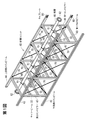
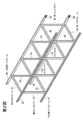
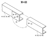
第1図は実施の形態に係る配管ユニットの斜視図、第2図は第1図の配管ユニットのラックの骨格フレームの斜視図、第3図は配管ユニット同士の連結体を示す斜視図、第4図はメインビーム同士の連結方法を示す斜視図、第5図はメインビーム同士の連結構造を示す斜視図である。 1 is a perspective view of a piping unit according to an embodiment, FIG. 2 is a perspective view of a skeleton frame of a rack of the piping unit of FIG. 1, FIG. 3 is a perspective view showing a coupling body of the piping units, FIG. FIG. 4 is a perspective view showing a method of connecting main beams, and FIG. 5 is a perspective view showing a connecting structure of main beams.
この配管ユニット40のラックは、メインビームとして、下段側の平行な1対の下段側メインビーム41,42と、該下段側メインビーム41,42と平行な1対の上段側メインビーム43,44とを有する。
The rack of the
該ラックは、エンドピラーとして、各メインビーム41〜44の一端側において立設された第1エンドピラー45,46と、各メインビーム41〜44の他端側において立設された第2エンドピラー47,48とを有する。
The rack, as end pillars, includes
該ラックは、クロスビームとして、該上段側メインビーム43,44の該一端側同士及び下段側メインビーム41,42の該一端側同士の間にそれぞれ架設された第1クロスビーム49,50と、該上段側メインビーム43,44の該他端側同士及び下段側メインビーム41,42の該他端側同士の間にそれぞれ架設された第2クロスビーム51,52とを有する。
The rack includes cross beams,
該ラックは、上段側メインビーム43と下段側メインビーム41及び上段側メインビーム44と下段側メインビーム42の長手方向の途中の複数箇所同士を連結する鉛直なサイドピラー53,54を有する。また、第1エンドピラー45,46同士の間、第2エンドピラー47,48同士の間、及びメインビーム41〜44の長手方向と直交方向において対峙する1対のサイドピラー53,53同士及びサイドピラー54,54同士の間に上下多段に架設されたキャリービーム55を有する。
The rack includes
配管ユニット40は、このように構成された直方格子形のラックに対し、該メインビーム41〜44と平行方向に延在するように配管60をキャリービーム55及び下段側のクロスビーム50,52にUボルト61で取り付けたものである。配管60の先端にはフランジ62が設けられている。
The
各メインビーム41〜44の一端側は第1エンドピラー45,46及び第1クロスビーム49,50よりも該メインビーム41〜44の長手方向の該一端側に延出しており、各メインビーム41〜44の該一端側の先端面と配管60の該一端側の先端面(フランジ面)とは面一状である。
One end side of each
各メインビーム41〜44の他端側は第2エンドピラー47,48及び第2クロスビーム51,52よりも該メインビーム41〜44の長手方向の該他端側に延出しており、各メインビーム41〜44の該他端側の先端面と配管60の該他端側の先端面(フランジ面)とは面一状である。
The other end side of each main beam 41-44 extends to the other end side in the longitudinal direction of the main beam 41-44 rather than the
上段側メインビーム43,44の該一端側の先端と下段側メインビーム41,42の該一端側の先端との間には縦材が不存在であり、上段側メインビーム43,44の該他端側の先端と下段側メインビーム41,42の該他端側の先端との間にも縦材が不存在である。
There is no vertical member between the tip of one end of the upper
該サイドピラー53又は54と、上段側メインビーム43又は44と、下段側メインビーム41又は42と、エンドピラー45,46,47又は48とで囲まれる方形枠状部に、対角線方向に鋼棒よりなる補強用ブレース70が架設されている。
A steel rod in a diagonal direction is formed in a rectangular frame portion surrounded by the
1対のサイドピラー53,54と、上段側メインビーム43と下段側メインビーム41とで囲まれる方形枠状部及び、1対のサイドピラー53,54と、上段側メインビーム44と下段側メインビーム42とで囲まれる方形枠状部にも、対角線方向に補強用ブレース70が架設されている。各ブレース70には、緊張用のターンバックル(図示略)が設けられている。
A rectangular frame-shaped portion surrounded by the pair of
各メインビーム41〜44の前記一端側の先端部の側面に、隣接配置される配管ユニット40への連結用のタイプレート80が取り付けられている。該タイプレート80は、該メインビーム41〜44の長手方向に長い長方形の平板状である。
A
長方形の該タイプレート80の長手方向の一端側が留付用ボルト84によって該メインビーム41〜44に留め付けられている。該留付用ボルト84は、該メインビーム41〜44の長手方向と直交方向かつ水平方向に延在している。
One end side in the longitudinal direction of the
該タイプレート80の他端側にはボルト挿通用の第1の孔81が設けられており、各メインビーム41〜44の前記他端側には、ボルト挿通用の第2の孔82が設けられている。
A
なお、図面を明瞭にするために、第1,3図では配管60は1本だけ図示されているが、実際には各キャリービーム55及び第1クロスビーム50上にも配管が設置されている。
In order to clarify the drawings, only one
第3図の通り、複数の配管ユニット40が配管60の長手方向に隣接配置され、各配管ユニット40,40のメインビーム41〜44同士及び配管60同士が連結される。
As shown in FIG. 3, a plurality of
第4,5図の通り、隣接する配管ユニット40,40同士を連結するには、一方の配管ユニット40のメインビーム41〜44の一端側のタイプレート80を前記留付用ボルト84回りに約180°回動させて他方の配管ユニット40のメインビーム41〜44の他端側に渡し込み、前記第1の孔81及び第2の孔82に締結用ボルト85を通してナット(図示略)締めする。これにより、配管ユニット40同士が簡易かつ強固に連結される。
As shown in FIGS. 4 and 5, in order to connect the
また、各配管ユニット40,40を連結すると、各々の配管60,60のフランジ62,62同士が重なり合うので、ボルト(図示略)によって両者を連結する。
Moreover, since the
なお、配管60の一方の端部がメインビーム41〜44の先端よりも所定長さだけ後退するように配管60の全長をメインビーム41〜44よりも該所定長さだけ短くしてもよい。この場合、該所定長さの軸長を有した伸縮可能な配管継手を、連結される配管60,60同士の間に介在させる。この配管継手は、配管60の熱膨張を吸収するためのものである。
Note that the entire length of the
このように構成された配管ユニット40及びその連結構造にあっては、メインビーム41〜44の両端同士を連結する縦材が存在しない。そのため、ラックが軽量である。
In the
この実施の形態では、ブレース70を設けたことにより、ラックの強度が高い。なお、ブレース70は軽量であり、ブレース設置に伴う重量増は微かである。
In this embodiment, the strength of the rack is high because the
この実施の形態によると、メインビーム41〜44同士を突き合わせてタイプレート80によって容易に連結することができる。また、配管60同士を突き合わせて容易に連結することができる。
According to this embodiment, the
即ち、この配管ユニット連結構造にあっては、この配管ユニット40同士がタイプレート80を介して連結されている。このタイプレート80がボルト84,85によってメインビーム41〜44に連結されるので、配管ユニット40,40同士の連結強度が高いものとなる。また、一方の配管ユニット40のタイプレート80をボルト84回りに約180°回し、タイプレート80を他方の配管ユニット40のメインビーム41〜44に渡し込んでボルト85留めすることにより、配管ユニット40,40同士を容易に連結することができると共に、両者の連結強度が高いものとなる。
That is, in this piping unit connection structure, the
上記の実施の形態は本発明の一例であり、本発明は図示の構成に限定されない。 The above embodiment is an example of the present invention, and the present invention is not limited to the illustrated configuration.
40 配管ユニット
41,42 下段側メインビーム
43,44 上段側メインビーム
45,46 第1エンドピラー
47,48 第2エンドピラー
49,50 第1クロスビーム
51,52 第2クロスビーム
53,54 サイドピラー
55 キャリービーム
60 配管
61 Uボルト
62 フランジ
70 ブレース
80 タイプレート
81 第1の孔
82 第2の孔
84 留付用ボルト
85 締結用ボルト
40
Claims (8)
該下段側メインビームと平行な1対の上段側メインビームと、
各メインビームの一端側において立設された第1エンドピラーと、
各メインビームの他端側において立設された第2エンドピラーと、
該上段側メインビームの該一端側同士及び下段側メインビームの該一端側同士の間にそれぞれ架設された第1クロスビームと、
該上段側メインビームの該他端側同士及び下段側メインビームの該他端側同士の間にそれぞれ架設された第2クロスビームと、
を有した直方格子形のラックに対し、該メインビームと平行方向に延在するように配管を取り付けた配管ユニットにおいて、
該メインビームの一端側は第1エンドピラー及び第1クロスビームよりも該メインビームの長手方向に延出しており、
該メインビームの他端側は第2エンドピラー及び第2クロスビームよりも該メインビームの長手方向に延出しており、
上段側メインビームの該一端側の先端と下段側メインビームの該一端側の先端との間には縦材が不存在であり、
上段側メインビームの該他端側の先端と下段側メインビームの該他端側の先端との間には縦材が不存在であることを特徴とする配管ユニット。 A pair of parallel lower main beams on the lower side;
A pair of upper main beams parallel to the lower main beam;
A first end pillar erected on one end side of each main beam;
A second end pillar erected on the other end of each main beam;
A first cross beam constructed between the one end sides of the upper main beam and the one end sides of the lower main beam;
A second cross beam constructed between the other ends of the upper main beam and the other ends of the lower main beam;
In a piping unit in which piping is attached so as to extend in a direction parallel to the main beam with respect to a rectangular lattice rack having
One end side of the main beam extends in the longitudinal direction of the main beam from the first end pillar and the first cross beam,
The other end side of the main beam extends in the longitudinal direction of the main beam from the second end pillar and the second cross beam,
There is no vertical member between the tip on the one end side of the upper main beam and the tip on the one end side of the lower main beam,
A piping unit characterized in that no vertical member is present between the tip of the upper main beam on the other end and the tip of the lower main beam on the other end.
該サイドピラーと、上段側メインビーム及び下段側メインビームと、前記エンドピラーとで囲まれる方形枠状部に、対角線方向に補強用ブレースが架設されていることを特徴とする配管ユニット。 In claim 1, while the middle of the longitudinal direction of the upper stage side main beam and the lower stage side main beam are connected by a vertical side pillar,
A piping unit characterized in that a reinforcing brace is constructed in a diagonal direction on a rectangular frame portion surrounded by the side pillar, the upper main beam, the lower main beam, and the end pillar.
1対の該サイドピラーと、上段側メインビーム及び下段側メインビームとで囲まれる方形枠状部に、対角線方向に補強用ブレースが架設されていることを特徴とする配管ユニット。 In claim 1, a plurality of locations in the longitudinal direction of the upper main beam and the lower main beam are connected by vertical side pillars,
A piping unit characterized in that a reinforcing brace is installed in a diagonal direction on a rectangular frame portion surrounded by a pair of the side pillars, an upper main beam and a lower main beam.
前記配管が該キャリービームに取り付けられていることを特徴とする配管ユニット。 In Claim 2 or 3, a carry beam is erected between the first end pillars, between the second end pillars, and between a pair of side pillars facing each other in the direction orthogonal to the main beam longitudinal direction. And
A piping unit, wherein the piping is attached to the carry beam.
該メインビームの一端側の先端面と前記配管の該一端側の先端面とは面一状であり、
該メインビームの他端側の先端面と前記配管の該他端側の先端面とは面一状であることを特徴とする配管ユニット。 In any one of Claims 1 thru | or 4,
The distal end surface on one end side of the main beam and the distal end surface on the one end side of the pipe are flush with each other,
A pipe unit, wherein a tip surface on the other end side of the main beam and a tip surface on the other end side of the pipe are flush with each other.
該タイプレートは、該メインビームの長手方向に延在した平板状であり、
該タイプレートのメインビーム一端側が留付用ボルトによって該メインビームに留め付けられており、該留付用ボルトは、該メインビームの長手方向と直交方向に延在しており、
該タイプレートの他端側にはボルト挿通用の第1の孔が設けられており、
各メインビームの前記他端側には、ボルト挿通用の第2の孔が設けられていることを特徴とする配管ユニット。 In any one of Claims 1 thru | or 5, the tie plate for connecting with the other end side of the main beam of the piping unit arrange | positioned adjacently is attached to the said one end side of each main beam,
The tie plate is a flat plate extending in the longitudinal direction of the main beam,
One end side of the main beam of the tie plate is fastened to the main beam by a fastening bolt, and the fastening bolt extends in a direction perpendicular to the longitudinal direction of the main beam,
A first hole for inserting a bolt is provided at the other end of the tie plate,
A piping unit, wherein a second hole for inserting a bolt is provided on the other end side of each main beam.
各配管ユニットのメインビーム同士及び配管同士が連結されていることを特徴とする配管ユニット連結構造。 The piping unit according to any one of claims 1 to 6 is arranged adjacent to the longitudinal direction of the piping,
A piping unit connecting structure characterized in that main beams and piping of each piping unit are connected.
隣接する配管ユニットのメインビーム同士は、一方の配管ユニットのメインビーム一端側のタイプレートを前記留付用ボルト回りに回動させて他方の配管ユニットのメインビーム他端側に渡し込み、前記第1の孔及び第2の孔に締結用ボルトを通してナット締めすることにより連結されていることを特徴とする配管ユニット連結構造。 In Claim 7, the said piping unit is a piping unit of Claim 6,
The main beams of the adjacent piping units rotate the tie plate on one end of the main beam of one piping unit around the fastening bolt and pass it to the other end of the main beam of the other piping unit. A piping unit connecting structure characterized in that it is connected to the first hole and the second hole by tightening a nut through a fastening bolt.
Priority Applications (1)
| Application Number | Priority Date | Filing Date | Title |
|---|---|---|---|
| JP2008215548A JP5282483B2 (en) | 2008-08-25 | 2008-08-25 | Piping unit and its connection structure |
Applications Claiming Priority (1)
| Application Number | Priority Date | Filing Date | Title |
|---|---|---|---|
| JP2008215548A JP5282483B2 (en) | 2008-08-25 | 2008-08-25 | Piping unit and its connection structure |
Publications (2)
| Publication Number | Publication Date |
|---|---|
| JP2010048398A true JP2010048398A (en) | 2010-03-04 |
| JP5282483B2 JP5282483B2 (en) | 2013-09-04 |
Family
ID=42065642
Family Applications (1)
| Application Number | Title | Priority Date | Filing Date |
|---|---|---|---|
| JP2008215548A Active JP5282483B2 (en) | 2008-08-25 | 2008-08-25 | Piping unit and its connection structure |
Country Status (1)
| Country | Link |
|---|---|
| JP (1) | JP5282483B2 (en) |
Cited By (3)
| Publication number | Priority date | Publication date | Assignee | Title |
|---|---|---|---|---|
| JP2017057944A (en) * | 2015-09-17 | 2017-03-23 | 株式会社東芝 | Pipe rack structure and installation method of pipe rack structure |
| CN107270271A (en) * | 2017-08-14 | 2017-10-20 | 哈尔滨哈锅锅炉工程技术有限公司 | A kind of fixing device for solving the expansion of boiler connecting pipe and being oriented to |
| KR102215093B1 (en) * | 2020-06-04 | 2021-02-10 | 성화시스템챤넬(주) | Rack modular for ceiling structure of building |
Families Citing this family (1)
| Publication number | Priority date | Publication date | Assignee | Title |
|---|---|---|---|---|
| JP7206740B2 (en) | 2018-09-25 | 2023-01-18 | 富士フイルムビジネスイノベーション株式会社 | Information processing device and program |
Citations (9)
| Publication number | Priority date | Publication date | Assignee | Title |
|---|---|---|---|---|
| JPS61197371U (en) * | 1985-05-30 | 1986-12-09 | ||
| JPH05231004A (en) * | 1992-02-26 | 1993-09-07 | Hitachi Ltd | Assembly of outdoor rack |
| JPH06341238A (en) * | 1993-05-31 | 1994-12-13 | Ishikawajima Harima Heavy Ind Co Ltd | Long size block and support structure thereof |
| JPH06343216A (en) * | 1993-05-31 | 1994-12-13 | Matsushita Electric Works Ltd | Cable rack |
| JPH08159339A (en) * | 1994-12-06 | 1996-06-21 | Takenaka Komuten Co Ltd | Piping laying rack |
| JP3033549U (en) * | 1996-07-12 | 1997-01-28 | 株式会社妻沼電化工業 | Prefabricated scaffolding |
| JPH11141740A (en) * | 1997-11-07 | 1999-05-28 | Kumagai Gumi Co Ltd | Method for transferring existing piping in cut and cover tunnel making work |
| JP2000274587A (en) * | 1999-03-25 | 2000-10-03 | Matsushita Electric Works Ltd | Connecting fitting of piping rack |
| JP2007032738A (en) * | 2005-07-28 | 2007-02-08 | Kurita Water Ind Ltd | Piping rack, water treatment plant and method of manufacturing the same |
-
2008
- 2008-08-25 JP JP2008215548A patent/JP5282483B2/en active Active
Patent Citations (9)
| Publication number | Priority date | Publication date | Assignee | Title |
|---|---|---|---|---|
| JPS61197371U (en) * | 1985-05-30 | 1986-12-09 | ||
| JPH05231004A (en) * | 1992-02-26 | 1993-09-07 | Hitachi Ltd | Assembly of outdoor rack |
| JPH06341238A (en) * | 1993-05-31 | 1994-12-13 | Ishikawajima Harima Heavy Ind Co Ltd | Long size block and support structure thereof |
| JPH06343216A (en) * | 1993-05-31 | 1994-12-13 | Matsushita Electric Works Ltd | Cable rack |
| JPH08159339A (en) * | 1994-12-06 | 1996-06-21 | Takenaka Komuten Co Ltd | Piping laying rack |
| JP3033549U (en) * | 1996-07-12 | 1997-01-28 | 株式会社妻沼電化工業 | Prefabricated scaffolding |
| JPH11141740A (en) * | 1997-11-07 | 1999-05-28 | Kumagai Gumi Co Ltd | Method for transferring existing piping in cut and cover tunnel making work |
| JP2000274587A (en) * | 1999-03-25 | 2000-10-03 | Matsushita Electric Works Ltd | Connecting fitting of piping rack |
| JP2007032738A (en) * | 2005-07-28 | 2007-02-08 | Kurita Water Ind Ltd | Piping rack, water treatment plant and method of manufacturing the same |
Cited By (3)
| Publication number | Priority date | Publication date | Assignee | Title |
|---|---|---|---|---|
| JP2017057944A (en) * | 2015-09-17 | 2017-03-23 | 株式会社東芝 | Pipe rack structure and installation method of pipe rack structure |
| CN107270271A (en) * | 2017-08-14 | 2017-10-20 | 哈尔滨哈锅锅炉工程技术有限公司 | A kind of fixing device for solving the expansion of boiler connecting pipe and being oriented to |
| KR102215093B1 (en) * | 2020-06-04 | 2021-02-10 | 성화시스템챤넬(주) | Rack modular for ceiling structure of building |
Also Published As
| Publication number | Publication date |
|---|---|
| JP5282483B2 (en) | 2013-09-04 |
Similar Documents
| Publication | Publication Date | Title |
|---|---|---|
| KR101354857B1 (en) | Strut having angle pipe section symmetrical with neural axis | |
| US8978338B2 (en) | Structural trusses with monolithic connector plate members | |
| US20110107709A1 (en) | Truss tower leg reinforcing system | |
| JP5282483B2 (en) | Piping unit and its connection structure | |
| KR20100023089A (en) | H-beam connecting structure | |
| JP6067403B2 (en) | Beam-to-column connection and steel beam connection at beam-to-column connection | |
| KR101520033B1 (en) | PSC composite truss girder | |
| CN102011432B (en) | Novel polygonal combined steel pipe | |
| JP6432786B2 (en) | Beam material load bearing structure and beam material repair method | |
| JP2010084489A (en) | Unit building | |
| JP4700419B2 (en) | Brace mounting structure | |
| JP4854310B2 (en) | Unit building | |
| JP5229709B1 (en) | Bracing joint for fire-fighting | |
| JP6072594B2 (en) | High rigidity beam | |
| JP6893789B2 (en) | Beam flint connection structure and beam flint connection piece | |
| CN104234189A (en) | Four-pipe truss structure of prefabricated house | |
| JP2008031644A (en) | Floor frame of steel frame building and construction method of this floor frame | |
| JP7063564B2 (en) | Floor panel structure, dry floor structure and method for manufacturing dry floor structure | |
| JP5010406B2 (en) | Building unit and unit building | |
| JP7358142B2 (en) | unit building | |
| JP2007231671A (en) | Unit building | |
| JP5612832B2 (en) | Unit building | |
| JP2012007352A (en) | Skeleton structure of parapet-type eaves with combined use of panel and unit | |
| JP2004137885A (en) | Connector for long material and its connecting structure | |
| CN207314202U (en) | A kind of traffic frame |
Legal Events
| Date | Code | Title | Description |
|---|---|---|---|
| A621 | Written request for application examination |
Free format text: JAPANESE INTERMEDIATE CODE: A621 Effective date: 20110706 |
|
| A977 | Report on retrieval |
Free format text: JAPANESE INTERMEDIATE CODE: A971007 Effective date: 20121213 |
|
| A131 | Notification of reasons for refusal |
Free format text: JAPANESE INTERMEDIATE CODE: A131 Effective date: 20130129 |
|
| A521 | Written amendment |
Free format text: JAPANESE INTERMEDIATE CODE: A523 Effective date: 20130325 |
|
| TRDD | Decision of grant or rejection written | ||
| A01 | Written decision to grant a patent or to grant a registration (utility model) |
Free format text: JAPANESE INTERMEDIATE CODE: A01 Effective date: 20130430 |
|
| A61 | First payment of annual fees (during grant procedure) |
Free format text: JAPANESE INTERMEDIATE CODE: A61 Effective date: 20130513 |
|
| R150 | Certificate of patent or registration of utility model |
Ref document number: 5282483 Country of ref document: JP Free format text: JAPANESE INTERMEDIATE CODE: R150 |