JP2010048382A - 回転軸の回転異常検出方法 - Google Patents
回転軸の回転異常検出方法 Download PDFInfo
- Publication number
- JP2010048382A JP2010048382A JP2008214781A JP2008214781A JP2010048382A JP 2010048382 A JP2010048382 A JP 2010048382A JP 2008214781 A JP2008214781 A JP 2008214781A JP 2008214781 A JP2008214781 A JP 2008214781A JP 2010048382 A JP2010048382 A JP 2010048382A
- Authority
- JP
- Japan
- Prior art keywords
- rotation
- connecting pin
- rotating shaft
- shaft
- rotating
- Prior art date
- Legal status (The legal status is an assumption and is not a legal conclusion. Google has not performed a legal analysis and makes no representation as to the accuracy of the status listed.)
- Granted
Links
Images


Landscapes
- Sliding-Contact Bearings (AREA)
Abstract
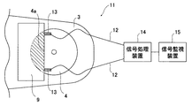
【解決手段】回り止めストッパによって被回転物に固定された回転軸と、該回転軸を支持する回転支持体との間の摺動状態の異常を検出する回転軸の回転異常検出方法であって、前記回転軸の前記回り止めストッパとの嵌合部近傍および/または前記回り止めストッパにひずみゲージを取り付け、該ひずみゲージの出力変化により、前記回転軸と前記回転支持体との間の摺動状態の異常を検知する。ヤード移動機に適用する場合、前記回転支持体がヤード移動機の基台上のブラケットであり、前記被回転物がブームであり、前記回転軸が連結ピンである。
【選択図】図2
Description
1.回り止めストッパによって被回転物に固定された回転軸と、該回転軸を支持する回転支持体との間の摺動状態の異常を検出する回転軸の回転異常検出方法であって、前記回転軸の前記回り止めストッパとの嵌合部近傍および/または前記回り止めストッパにひずみゲージを取り付け、該ひずみゲージの出力変化により、前記回転軸と前記回転支持体との間の摺動状態の異常を検知することを特徴とする回転軸の回転異常検出方法。
2.前記回転支持体がヤード移動機の基台上のブラケットであり、前記被回転物がブームであり、前記回転軸が連結ピンであることを特徴とする上記1.記載の回転軸の回転異常検出方法。
1.無人操作されている移動機の連結ピンにおけるかじり等の回転異常を早期に発見できる。計測には、ひずみゲージ・測定機器を設置するのみであり、連結ピン・ブラケット・ピン穴に特別な改造を実施する必要がない。
2.ブーム回転時の発生応力を測定するため、移動機の作業中の振動等の外乱により、検出能力が影響されることが無い。
3.ブーム回転時における発生応力を常時監視・傾向管理することで、定常時の発生応力よりも応力レベルの変動が大きければ、連結ピンの給脂量が少なくなり、給脂が必要であることを早期に発見することができる。
4.また、連結ピンのブームと連結ピンの嵌合い部よりも外側にひずみゲージを設置するため、設置のために連結ピンを抜く必要が無く、設備稼働後も簡単に検出装置を設置することができる。
2 テンションバー
3 ブーム
4 連結ピン
5 バランスウエイト
6 回転シャベル
7 ブッシュ
8 ブラケット
9 回り止めストッパ
10、13 ひずみゲージ
11 連結ピン取り付け部
12 信号線
14 信号処理装置
15 信号監視装置
Claims (2)
- 回り止めストッパによって被回転物に固定された回転軸と、該回転軸を支持する回転支持体との間の摺動状態の異常を検出する回転軸の回転異常検出方法であって、前記回転軸の前記回り止めストッパとの嵌合部近傍および/または前記回り止めストッパにひずみゲージを取り付け、該ひずみゲージの出力変化により、前記回転軸と前記回転支持体との間の摺動状態の異常を検知することを特徴とする回転軸の回転異常検出方法。
- 前記回転支持体がヤード移動機の基台上のブラケットであり、前記被回転物がブームであり、前記回転軸が連結ピンであることを特徴とする請求項1記載の回転軸の回転異常検出方法。
Priority Applications (1)
| Application Number | Priority Date | Filing Date | Title |
|---|---|---|---|
| JP2008214781A JP5125882B2 (ja) | 2008-08-25 | 2008-08-25 | 連結ピンの回転異常検出方法 |
Applications Claiming Priority (1)
| Application Number | Priority Date | Filing Date | Title |
|---|---|---|---|
| JP2008214781A JP5125882B2 (ja) | 2008-08-25 | 2008-08-25 | 連結ピンの回転異常検出方法 |
Publications (2)
| Publication Number | Publication Date |
|---|---|
| JP2010048382A true JP2010048382A (ja) | 2010-03-04 |
| JP5125882B2 JP5125882B2 (ja) | 2013-01-23 |
Family
ID=42065626
Family Applications (1)
| Application Number | Title | Priority Date | Filing Date |
|---|---|---|---|
| JP2008214781A Expired - Fee Related JP5125882B2 (ja) | 2008-08-25 | 2008-08-25 | 連結ピンの回転異常検出方法 |
Country Status (1)
| Country | Link |
|---|---|
| JP (1) | JP5125882B2 (ja) |
Citations (3)
| Publication number | Priority date | Publication date | Assignee | Title |
|---|---|---|---|---|
| JPS56162033A (en) * | 1980-05-19 | 1981-12-12 | Mitsubishi Electric Corp | Abnormality monitoring device for bearing load of rotating machine |
| JP2003176815A (ja) * | 2001-12-11 | 2003-06-27 | Komatsu Ltd | 軸受装置 |
| JP2005119774A (ja) * | 2003-10-15 | 2005-05-12 | Mitsui Miike Mach Co Ltd | ブームの接触防止装置 |
-
2008
- 2008-08-25 JP JP2008214781A patent/JP5125882B2/ja not_active Expired - Fee Related
Patent Citations (3)
| Publication number | Priority date | Publication date | Assignee | Title |
|---|---|---|---|---|
| JPS56162033A (en) * | 1980-05-19 | 1981-12-12 | Mitsubishi Electric Corp | Abnormality monitoring device for bearing load of rotating machine |
| JP2003176815A (ja) * | 2001-12-11 | 2003-06-27 | Komatsu Ltd | 軸受装置 |
| JP2005119774A (ja) * | 2003-10-15 | 2005-05-12 | Mitsui Miike Mach Co Ltd | ブームの接触防止装置 |
Also Published As
| Publication number | Publication date |
|---|---|
| JP5125882B2 (ja) | 2013-01-23 |
Similar Documents
| Publication | Publication Date | Title |
|---|---|---|
| CN101213436B (zh) | 用于计算轴承寿命的电机接口模块设备 | |
| EP2019926B1 (en) | Bearing failure indicator | |
| US7963701B2 (en) | System and method for setting roller skew | |
| JP2009109350A (ja) | 回転機械装置の監視診断システム | |
| US10605623B1 (en) | No-backlash rotation measurement system | |
| WO2017203868A1 (ja) | 転がり軸受疲労状態予測装置及び転がり軸受疲労状態予測方法 | |
| KR101374840B1 (ko) | 해양구조물의 회전체 상태진단 시스템 및 방법 | |
| JP2017156151A (ja) | トルク計測装置、歯車箱及びトルク計測方法 | |
| US20180305187A1 (en) | Drum-type conveying installation with cable-monitoring device | |
| CN115397723A (zh) | 作业车辆部件 | |
| JP5125882B2 (ja) | 連結ピンの回転異常検出方法 | |
| JP6592061B2 (ja) | ベルトの交換判定装置および交換判定方法 | |
| WO2018173832A1 (ja) | 状態監視装置 | |
| WO2012162853A1 (en) | Sheave monitor | |
| WO2022264047A1 (en) | Wear monitoring system and method for monitoring bearing wear in a roller for an undercarriage track system | |
| JP6939994B2 (ja) | 溝摩耗検知装置 | |
| CN103407892A (zh) | 超起装置张开角度检测系统及方法 | |
| JP5981120B2 (ja) | 風力発電装置の状態監視システム | |
| US12235184B2 (en) | Rotary encoder and a method for monitoring operation of the rotary encoder | |
| JP2000170477A (ja) | シールド掘進機のカッタ前面荷重検出方法及び装置並びにシールド掘進機 | |
| JP2021183925A (ja) | ボルト型センサ装置、ボルト本体、風車用駆動装置、風車および締結構造 | |
| JP7425994B2 (ja) | シックナーレーキ旋回軸受点検装置 | |
| JP2006177774A (ja) | 転がり軸受の動トルク測定方法と測定装置及び転がり軸受の異常検知方法及び異常検知装置 | |
| CA2890668A1 (en) | Self-aligning shaft assembly | |
| EP4667779A1 (en) | Strain wave gear device with torque sensor |
Legal Events
| Date | Code | Title | Description |
|---|---|---|---|
| A621 | Written request for application examination |
Free format text: JAPANESE INTERMEDIATE CODE: A621 Effective date: 20110128 |
|
| A977 | Report on retrieval |
Free format text: JAPANESE INTERMEDIATE CODE: A971007 Effective date: 20120209 |
|
| A131 | Notification of reasons for refusal |
Free format text: JAPANESE INTERMEDIATE CODE: A131 Effective date: 20120214 |
|
| RD03 | Notification of appointment of power of attorney |
Free format text: JAPANESE INTERMEDIATE CODE: A7423 Effective date: 20120321 |
|
| RD04 | Notification of resignation of power of attorney |
Free format text: JAPANESE INTERMEDIATE CODE: A7424 Effective date: 20120327 |
|
| A521 | Request for written amendment filed |
Free format text: JAPANESE INTERMEDIATE CODE: A523 Effective date: 20120411 |
|
| A131 | Notification of reasons for refusal |
Free format text: JAPANESE INTERMEDIATE CODE: A131 Effective date: 20120724 |
|
| A521 | Request for written amendment filed |
Free format text: JAPANESE INTERMEDIATE CODE: A523 Effective date: 20120904 |
|
| TRDD | Decision of grant or rejection written | ||
| A01 | Written decision to grant a patent or to grant a registration (utility model) |
Free format text: JAPANESE INTERMEDIATE CODE: A01 Effective date: 20121002 |
|
| A01 | Written decision to grant a patent or to grant a registration (utility model) |
Free format text: JAPANESE INTERMEDIATE CODE: A01 |
|
| A61 | First payment of annual fees (during grant procedure) |
Free format text: JAPANESE INTERMEDIATE CODE: A61 Effective date: 20121015 |
|
| R150 | Certificate of patent or registration of utility model |
Free format text: JAPANESE INTERMEDIATE CODE: R150 Ref document number: 5125882 Country of ref document: JP Free format text: JAPANESE INTERMEDIATE CODE: R150 |
|
| FPAY | Renewal fee payment (event date is renewal date of database) |
Free format text: PAYMENT UNTIL: 20151109 Year of fee payment: 3 |
|
| R250 | Receipt of annual fees |
Free format text: JAPANESE INTERMEDIATE CODE: R250 |
|
| LAPS | Cancellation because of no payment of annual fees |