JP2010047340A - Monitoring system of conveyor belt - Google Patents
Monitoring system of conveyor belt Download PDFInfo
- Publication number
- JP2010047340A JP2010047340A JP2008211436A JP2008211436A JP2010047340A JP 2010047340 A JP2010047340 A JP 2010047340A JP 2008211436 A JP2008211436 A JP 2008211436A JP 2008211436 A JP2008211436 A JP 2008211436A JP 2010047340 A JP2010047340 A JP 2010047340A
- Authority
- JP
- Japan
- Prior art keywords
- conveyor belt
- detection unit
- antenna
- transmission
- unit
- Prior art date
- Legal status (The legal status is an assumption and is not a legal conclusion. Google has not performed a legal analysis and makes no representation as to the accuracy of the status listed.)
- Granted
Links
Images


Abstract
Description
本発明は、物理量を検出する検出ユニットをコンベヤベルトに埋設してコンベヤベルトをモニタリングするシステムに関する。 The present invention relates to a system for monitoring a conveyor belt by embedding a detection unit for detecting a physical quantity in the conveyor belt.
ベルトコンベヤ装置にはコンベヤベルトを支持するためのローラが移送方向に沿って多数配列されている。このローラは運搬物の荷重を直接受けるため磨耗損傷等により回転不良が発生しやすく、ローラに回転不良が発生するとコンベヤベルトを摩耗損傷させてコンベヤベルトの耐久性を著しく低下させる。ローラの回転不良を検知する方法として、保守作業員がコンベヤに沿って巡回し、目視や触診により、またはローラからの異音を聞き分けて不具合なローラを特定する方法が知られているが、鉱山等で使用される機長の長いベルトコンベヤ装置においては、多数のローラが配列されていることから、保守作業員に多くの労力と時間を強いるという問題があった。
そこで、コンベヤベルトの内部にセンサ、CPU、メモリ、バッテリ、送受信ユニットを小型化した検出ユニットを埋め込み、ベルト走行時にセンサからの信号をCPUで処理し、メモリに記録し、検出ユニットが外部の固定受信センサを通過した際に、非接触にデータを送受信できるシステムが提案されている(特許文献1参照)。
Therefore, a sensor, CPU, memory, battery, and a detection unit with a small transmission / reception unit are embedded inside the conveyor belt, and the signal from the sensor is processed by the CPU during belt running and recorded in the memory. The detection unit is fixed externally. A system that can transmit and receive data in a non-contact manner when passing through a receiving sensor has been proposed (see Patent Document 1).
ところで、検出ユニットには、外部の固定受信装置と無線によりデータを送受信するためにアンテナが設けられており、このアンテナには、特許文献1にも示すように、一般に平板環状アンテナが用いられている。
そのため、従来の検出ユニットでは、送受信範囲が、アンテナのコンベヤベルト進行方向の長さしかなく、送受信範囲が狭いために、送受信の精度が低いという問題があった。
また、アンテナが、コンベヤベルトの幅方向に広がるため、コンベヤベルトの縦裂きによりアンテナが断線し、検出ユニットが破損することがあった。
By the way, the detection unit is provided with an antenna for wirelessly transmitting and receiving data to and from an external fixed reception device. As shown in Patent Document 1, a flat annular antenna is generally used for this antenna. Yes.
For this reason, the conventional detection unit has a problem in that the transmission / reception range is only the length of the antenna in the traveling direction of the conveyor belt and the transmission / reception range is narrow, so that the transmission / reception accuracy is low.
In addition, since the antenna spreads in the width direction of the conveyor belt, the antenna may be disconnected due to the longitudinal tearing of the conveyor belt, and the detection unit may be damaged.
本発明は、このような問題点に鑑みてなされたものであり、本発明の目的は、検出ユニットの送受信範囲が広く、コンベヤベルトの縦裂きによる検出ユニットの破損の可能性が低いコンベヤベルトのモニタリングシステムを提供することにある。 The present invention has been made in view of such problems, and an object of the present invention is to provide a conveyor belt having a wide transmission / reception range of the detection unit and a low possibility of breakage of the detection unit due to longitudinal tearing of the conveyor belt. To provide a monitoring system.
上記目的を達成するため、本発明は、コンベヤベルトに、アンテナと内部ユニットからなる検出ユニットを設け、前記内部ユニットを、物理量を検知するセンサと、該センサから得られたデータを格納するメモリと、メモリに格納されたデータをコンベヤベルトの外に電波で送信する送信手段とで構成するともに、コンベヤベルトの外に、前記送信手段から送信されたデータを受信する受信手段を設けてコンベヤベルトをモニタリングするシステムであって、前記検出ユニットのアンテナが長尺形状であり、該アンテナが前記コンベヤベルトの搬送方向に縦長に配置されていることを特徴とする。 In order to achieve the above object, the present invention provides a detection unit comprising an antenna and an internal unit on a conveyor belt, wherein the internal unit includes a sensor for detecting a physical quantity, and a memory for storing data obtained from the sensor. And a transmission means for transmitting data stored in the memory by radio waves to the outside of the conveyor belt, and a receiving means for receiving the data transmitted from the transmission means is provided outside the conveyor belt. In the monitoring system, the antenna of the detection unit has an elongated shape, and the antenna is arranged vertically in the conveying direction of the conveyor belt.
前記アンテナと前記内部ユニットは、前記コンベヤベルトの搬送方向に直列に配置されていることが好ましい。また、前記内部ユニットの構成部品は、前記コンベヤベルトの搬送方向に直列に配置されていることが好ましい。また、前記検出ユニットは、前記コンベヤベルトの幅方向端部に配置されていることが好ましい。 It is preferable that the antenna and the internal unit are arranged in series in the conveying direction of the conveyor belt. Moreover, it is preferable that the component of the said internal unit is arrange | positioned in series in the conveyance direction of the said conveyor belt. Moreover, it is preferable that the said detection unit is arrange | positioned at the width direction edge part of the said conveyor belt.
本発明は、検出ユニットのアンテナが長尺形状であり、このアンテナがコンベヤベルトの搬送方向に縦長に配置されているので、検出ユニットの送受信範囲が広くなる。そのため、送受信できる時間が長くなり、信号を確実に受信できるようになるため、送受信の精度の向上させることができる。また、アンテナがコンベヤベルトの幅方向に狭くなっているため、コンベヤベルトの縦裂きによるアンテナの破損可能性を最小限に抑えることができる。
また、本発明は、アンテナと内部ユニットが、コンベヤベルトの搬送方向に直列に配置されているので、コンベヤベルトの縦裂きによる内部ユニットの破損可能性を低く抑えることができる。
また、本発明は、内部ユニットの構成部品が、コンベヤベルトの搬送方向に直列に配置されているので、コンベヤベルトの縦裂きによる内部ユニットの破損可能性を更に低く抑えることができる。
また、本発明は、検出ユニットが、被搬送物による縦裂きが比較的起こり難い場所であるコンベヤベルトの幅方向端部に配置されているので、検出ユニットの破損可能性を最小限に抑えることができる。
In the present invention, since the antenna of the detection unit has an elongated shape and this antenna is arranged vertically in the conveying direction of the conveyor belt, the transmission / reception range of the detection unit is widened. Therefore, since the time during which transmission / reception can be performed becomes longer and signals can be received reliably, transmission / reception accuracy can be improved. Moreover, since the antenna is narrow in the width direction of the conveyor belt, the possibility of damage to the antenna due to the longitudinal tearing of the conveyor belt can be minimized.
Further, according to the present invention, since the antenna and the internal unit are arranged in series in the conveying direction of the conveyor belt, the possibility of breakage of the internal unit due to the longitudinal tearing of the conveyor belt can be suppressed low.
Moreover, since the component of the internal unit is arrange | positioned in series with the conveyance direction of a conveyor belt, this invention can further suppress the possibility of failure | damage of an internal unit by the longitudinal tear of a conveyor belt.
In addition, the present invention minimizes the possibility of breakage of the detection unit because the detection unit is disposed at the end in the width direction of the conveyor belt, which is a place where the longitudinal tearing by the conveyed object is relatively difficult. Can do.
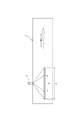
本発明の実施の形態について図面を参照して説明する。図1は、本発明のコンベヤベルトのモニタリングシステムを示す概念図である。図1に示すコンベヤベルトのモニタリングシステムは、無端のコンベヤベルト1に埋設された検出ユニット2と、検出ユニット2とデータの送受信を行う送受信装置5と、送受信装置5に接続されたデータ処理手段とを具えて構成される。図1は、コンベヤベルト1を側面方向から視たものであり、コンベヤベルト1を部分的に表示している。コンベヤベルト1は、矢印Aで示すように、左方から右方へ向かって進行する。検出ユニット2は、コンベヤベルト1の下面1aに埋設されており、送受信装置5のアンテナ7は、コンベヤベルト1の下方に、コンベヤベルト1から所定距離離間して配設されている。
検出ユニット2は、コンベヤベルト1が受ける物理量を連続的に検出し、検出した情報を送受信装置5に送信する機能を有している。
送受信装置5は、検出ユニット2から情報を受信したときは、その情報をデータ処理装置6に送信し、データ処理装置6は定常的な値と比較することによって、異常な事態の発生を判断する。
Embodiments of the present invention will be described with reference to the drawings. FIG. 1 is a conceptual diagram illustrating a conveyor belt monitoring system according to the present invention. The conveyor belt monitoring system shown in FIG. 1 includes a
The
When receiving information from the
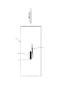
図2は、コンベヤベルトに埋め込まれる検出ユニットの構成を示す図である。検出ユニット2は、アンテナ11と内部ユニット12により構成されており、内部ユニット12は、コンベヤベルトが受ける物理量を検知するセンサ16、センサ16からのデータを処理するCPU15、センサ16から得られたデータを格納するメモリ14、メモリ14に格納されたデータをコンベヤベルトの外に電波で送信する送受信ユニット13およびバッテリ17を備えている。
センサ16は、例えば、圧力センサであり、コンベヤベルト1の表面にかかる圧力を連続的に検出し、CPU15は、コンベヤベルト1の走行時にセンサ16からの信号を処理し、メモリ14に記録する。そして、検出ユニット2は、コンベヤベルト1の外部に配設されている送受信装置5のアンテナ7を通過した際に、送受信ユニット13から電波でデータを送受信装置5に送信する。
FIG. 2 is a diagram showing a configuration of a detection unit embedded in the conveyor belt. The
The
アンテナ11は、長尺の形状をしており、コンベヤベルト1の搬送方向に縦長に配置されている。このように、長尺形状のアンテナ11をコンベヤベルト1の搬送方向に縦長に配置すると、図3に示すように、コンベヤベルト1の長さ方向の送受信範囲が広くなり、送受信範囲が広くなると、送受信できる時間が長くなり、信号を確実に受信できるようになるため、送受信の精度の向上させることができる。図3において、Bは従来の検出ユニットの送受信範囲を示しており、Cは本発明の検出ユニットの送受信範囲を示している。
なお、送受信の精度の向上を見込むためには、アンテナ11の長手方向の長さと、長手方向に対して直交する方向の長さの比の値は1.5以上であることが好ましい。
The
In order to expect improvement in transmission / reception accuracy, the ratio of the length in the longitudinal direction of the
また、アンテナ11と内部ユニット12は、アンテナ11の長手方向(コンベヤベルトの搬送方向)に直列に配置されている。また、内部ユニット12の構成部品である送受信ユニット13、メモリ14、CPU15、センサ16およびバッテリ17もそれぞれ、内部ユニット12内において、アンテナ11の長手方向(コンベヤベルトの搬送方向)に直列に配置されている。このように、長尺なアンテナの長手方向に構成部品が直列に配置されているので、検出ユニット12自体の形状も長尺形状となっている。
The
このように、アンテナ11と内部ユニット12をアンテナ11の長手方向(コンベヤベルトの搬送方向)に直列に配置し、内部ユニット12の構成部品をアンテナ11の長手方向(コンベヤベルトの搬送方向)に直列に配置すると、検出ユニット12自体が長尺になるため、ベルトの縦裂時において検出ユニットが破損する可能性を最小限に抑えることができる。図4は、従来の検出ユニットと本発明の検出ユニットとの破損可能性を比較して説明する図である。コンベヤベルト1には縦裂4が発生している。点線で示すのが従来の検出ユニット3であり、従来の検出ユニット3と比較して、本発明の検出ユニット2は、コンベヤベルトの幅方向に狭くなっているので、縦裂4で破損する可能性が従来品に比べて低くなる。
Thus, the
なお、検出ユニット2が埋め込まれる位置は、コンベヤベルトの幅方向のいずれの位置でもよいが、コンベヤベルトの幅方向端部が好ましい。端部は、被搬送物による縦裂きが比較的起こり難い場所であるためである。検出ユニットをコンベヤベルトの幅方向端部に配置することで、検出ユニットの破損可能性を最小限に抑えることができる。
また、アンテナは、可撓性材料(例えば、ゴムまたは布)により被覆することが好ましい。アンテナを可撓性材料で被覆することにより、コンベヤベルトの屈曲によるアンテナの破壊を防ぐことができる。
The position where the
The antenna is preferably covered with a flexible material (for example, rubber or cloth). By covering the antenna with a flexible material, it is possible to prevent the antenna from being broken due to the bending of the conveyor belt.
1 コンベヤベルト
2 検出ユニット
3 検出ユニット(従来)
5 送受信装置
6 データ処理手段
7,11 アンテナ
12 内部ユニット
13 送受信ユニット
14 メモリ
15 CPU
16 センサ
17 バッテリ
1
DESCRIPTION OF
16
Claims (4)
前記検出ユニットのアンテナは長尺形状であり、該アンテナは前記コンベヤベルトの搬送方向に縦長に配置されていることを特徴とするコンベヤベルトのモニタリングシステム。 A detection unit comprising an antenna and an internal unit is provided on the conveyor belt, and the internal unit has a sensor for detecting a physical quantity received by the conveyor belt, a memory for storing data obtained from the sensor, and data stored in the memory. A system for monitoring the conveyor belt by providing a receiving means for receiving data transmitted from the transmitting means outside the conveyor belt,
The conveyor belt monitoring system according to claim 1, wherein the antenna of the detection unit has an elongated shape, and the antenna is arranged vertically in the conveying direction of the conveyor belt.
Priority Applications (1)
| Application Number | Priority Date | Filing Date | Title |
|---|---|---|---|
| JP2008211436A JP5279406B2 (en) | 2008-08-20 | 2008-08-20 | Conveyor belt monitoring system |
Applications Claiming Priority (1)
| Application Number | Priority Date | Filing Date | Title |
|---|---|---|---|
| JP2008211436A JP5279406B2 (en) | 2008-08-20 | 2008-08-20 | Conveyor belt monitoring system |
Publications (2)
| Publication Number | Publication Date |
|---|---|
| JP2010047340A true JP2010047340A (en) | 2010-03-04 |
| JP5279406B2 JP5279406B2 (en) | 2013-09-04 |
Family
ID=42064788
Family Applications (1)
| Application Number | Title | Priority Date | Filing Date |
|---|---|---|---|
| JP2008211436A Expired - Fee Related JP5279406B2 (en) | 2008-08-20 | 2008-08-20 | Conveyor belt monitoring system |
Country Status (1)
| Country | Link |
|---|---|
| JP (1) | JP5279406B2 (en) |
Cited By (3)
| Publication number | Priority date | Publication date | Assignee | Title |
|---|---|---|---|---|
| CN102358505A (en) * | 2011-06-28 | 2012-02-22 | 太原理工大学 | Conveyor belt longitudinal-tearing online monitoring early warning device |
| US11312804B2 (en) | 2018-02-16 | 2022-04-26 | Jnc Corporation | Polymerizable compound, polymerizable composition, polymer, and photoresist composition |
| CN114955449A (en) * | 2022-05-19 | 2022-08-30 | 华能曲阜热电有限公司 | Early warning device is torn to feeder belt |
Families Citing this family (1)
| Publication number | Priority date | Publication date | Assignee | Title |
|---|---|---|---|---|
| EP4039619A1 (en) | 2021-02-05 | 2022-08-10 | Aumund Fördertechnik GmbH | Conveyor with clamping connection and method for operating a conveyor |
Citations (5)
| Publication number | Priority date | Publication date | Assignee | Title |
|---|---|---|---|---|
| US3651506A (en) * | 1969-09-30 | 1972-03-21 | Bergwerksverband Gmbh | Conveyor band monitoring apparatus |
| US3742477A (en) * | 1971-09-09 | 1973-06-26 | Goodyear Tire & Rubber | Conveyor belt condition monitoring apparatus |
| JPS54118085A (en) * | 1978-03-06 | 1979-09-13 | Sumitomo Metal Ind Ltd | Abnormal condition detector of conveyor belt |
| WO2000053517A1 (en) * | 1999-03-10 | 2000-09-14 | Canada Conveyor Belt Co., Ltd. | Conveyor belt fault detection apparatus and method |
| JP2006052039A (en) * | 2004-08-10 | 2006-02-23 | Bridgestone Corp | Conveyor belt monitoring system |
-
2008
- 2008-08-20 JP JP2008211436A patent/JP5279406B2/en not_active Expired - Fee Related
Patent Citations (5)
| Publication number | Priority date | Publication date | Assignee | Title |
|---|---|---|---|---|
| US3651506A (en) * | 1969-09-30 | 1972-03-21 | Bergwerksverband Gmbh | Conveyor band monitoring apparatus |
| US3742477A (en) * | 1971-09-09 | 1973-06-26 | Goodyear Tire & Rubber | Conveyor belt condition monitoring apparatus |
| JPS54118085A (en) * | 1978-03-06 | 1979-09-13 | Sumitomo Metal Ind Ltd | Abnormal condition detector of conveyor belt |
| WO2000053517A1 (en) * | 1999-03-10 | 2000-09-14 | Canada Conveyor Belt Co., Ltd. | Conveyor belt fault detection apparatus and method |
| JP2006052039A (en) * | 2004-08-10 | 2006-02-23 | Bridgestone Corp | Conveyor belt monitoring system |
Cited By (5)
| Publication number | Priority date | Publication date | Assignee | Title |
|---|---|---|---|---|
| CN102358505A (en) * | 2011-06-28 | 2012-02-22 | 太原理工大学 | Conveyor belt longitudinal-tearing online monitoring early warning device |
| CN102358505B (en) * | 2011-06-28 | 2013-04-03 | 太原理工大学 | Conveyor belt longitudinal-tearing online monitoring early warning device |
| US11312804B2 (en) | 2018-02-16 | 2022-04-26 | Jnc Corporation | Polymerizable compound, polymerizable composition, polymer, and photoresist composition |
| CN114955449A (en) * | 2022-05-19 | 2022-08-30 | 华能曲阜热电有限公司 | Early warning device is torn to feeder belt |
| CN114955449B (en) * | 2022-05-19 | 2023-11-03 | 华能曲阜热电有限公司 | Early warning device is torn to feeder belt |
Also Published As
| Publication number | Publication date |
|---|---|
| JP5279406B2 (en) | 2013-09-04 |
Similar Documents
| Publication | Publication Date | Title |
|---|---|---|
| JP5279406B2 (en) | Conveyor belt monitoring system | |
| US9988217B2 (en) | Conveyor belt wear monitoring system | |
| WO2010016495A1 (en) | Belt support roller monitoring system | |
| US20090194390A1 (en) | Apparatus and method for in-belt conveyor idler condition monitoring | |
| JP2007131457A (en) | Method for self-synchronizing conveyor belt sensor system | |
| JP5318611B2 (en) | Defect judgment system for conveyor belts and guide rollers | |
| JP2006052039A (en) | Conveyor belt monitoring system | |
| CN104655715A (en) | Method for monitoring conveyor belt splices | |
| JP5138285B2 (en) | Method of embedding electronic equipment on conveyor belt and protective case for electronic equipment | |
| JP6164182B2 (en) | Abnormality detection method for belt conveyor | |
| JP2012046328A (en) | Detector for vertical-split of conveyor belt | |
| JP5503224B2 (en) | Conveyor belt and belt conveyor device | |
| CN107117446A (en) | A kind of mechanical contact belt deviation amount detecting device and its measuring method | |
| JP5318610B2 (en) | Defect judgment system for conveyor belts and guide rollers | |
| CN108657730B (en) | Device and method for monitoring real-time belt breakage of belt conveyor | |
| JPH0648533A (en) | Belt meandering detecting method | |
| JP5456999B2 (en) | Belt support roller monitoring system | |
| CN105283395A (en) | Splice monitoring system for conveyor belts in mining industry | |
| JP2010111504A (en) | Monitoring system of conveyor belt | |
| KR101246316B1 (en) | Sensing device for damage of belt conveyor | |
| Banerjee et al. | Conveyor belt health monitoring | |
| JP7136153B2 (en) | Sensor device and anomaly monitoring device | |
| KR102157871B1 (en) | Apparatus for detecting separation of bearing | |
| JP2016168814A (en) | Rubber strip winding device | |
| CN105293002B (en) | The belt longitudinal tear detection method of view-based access control model |
Legal Events
| Date | Code | Title | Description |
|---|---|---|---|
| A621 | Written request for application examination |
Free format text: JAPANESE INTERMEDIATE CODE: A621 Effective date: 20110808 |
|
| A977 | Report on retrieval |
Free format text: JAPANESE INTERMEDIATE CODE: A971007 Effective date: 20130322 |
|
| TRDD | Decision of grant or rejection written | ||
| A01 | Written decision to grant a patent or to grant a registration (utility model) |
Free format text: JAPANESE INTERMEDIATE CODE: A01 Effective date: 20130423 |
|
| A61 | First payment of annual fees (during grant procedure) |
Free format text: JAPANESE INTERMEDIATE CODE: A61 Effective date: 20130521 |
|
| R150 | Certificate of patent or registration of utility model |
Free format text: JAPANESE INTERMEDIATE CODE: R150 |
|
| LAPS | Cancellation because of no payment of annual fees |