JP2010046806A - Image forming apparatus - Google Patents
Image forming apparatus Download PDFInfo
- Publication number
- JP2010046806A JP2010046806A JP2008210367A JP2008210367A JP2010046806A JP 2010046806 A JP2010046806 A JP 2010046806A JP 2008210367 A JP2008210367 A JP 2008210367A JP 2008210367 A JP2008210367 A JP 2008210367A JP 2010046806 A JP2010046806 A JP 2010046806A
- Authority
- JP
- Japan
- Prior art keywords
- ink
- recording head
- head
- unit
- image forming
- Prior art date
- Legal status (The legal status is an assumption and is not a legal conclusion. Google has not performed a legal analysis and makes no representation as to the accuracy of the status listed.)
- Granted
Links
Images


Abstract
Description
本発明は画像形成装置に関し、特に液滴を吐出する記録ヘッドを備える画像形成装置におけるインク供給装置に関する。 The present invention relates to an image forming apparatus, and more particularly to an ink supply apparatus in an image forming apparatus including a recording head that ejects droplets.
プリンタ、ファクシミリ、複写装置、プロッタ、これらの複合機等の画像形成装置として、例えばインク液滴を吐出する記録ヘッドを用いた液体吐出記録方式の画像形成装置としてインクジェット記録装置などが知られている。この液体吐出記録方式の画像形成装置は、記録ヘッドからインク滴を、搬送される用紙(紙に限定するものではなく、OHPなどを含み、インク滴、その他の液体などが付着可能なものの意味であり、被記録媒体あるいは記録媒体、記録紙、記録用紙などとも称される。)に対して吐出して、画像形成(記録、印字、印写、印刷も同義語で使用する。)を行なうものであり、記録ヘッドが主走査方向に移動しながら液滴を吐出して画像を形成するシリアル型画像形成装置と、記録ヘッドが移動しない状態で液滴を吐出して画像を形成するライン型ヘッドを用いるライン型画像形成装置がある。 As an image forming apparatus such as a printer, a facsimile machine, a copying apparatus, a plotter, and a complex machine of these, for example, an ink jet recording apparatus is known as an image forming apparatus of a liquid discharge recording method using a recording head for discharging ink droplets. . This liquid discharge recording type image forming apparatus means that ink droplets are transported from a recording head (not limited to paper, including OHP, and can be attached to ink droplets and other liquids). Yes, it is also ejected onto a recording medium or a recording medium, recording paper, recording paper, etc.) to form an image (recording, printing, printing, and printing are also used synonymously). And a serial type image forming apparatus that forms an image by ejecting liquid droplets while the recording head moves in the main scanning direction, and a line type head that forms images by ejecting liquid droplets without moving the recording head There are line type image forming apparatuses using
なお、本願において、液体吐出方式の「画像形成装置」は、紙、糸、繊維、布帛、皮革、金属、プラスチック、ガラス、木材、セラミックス等の媒体に液体を吐出して画像形成を行う装置を意味し、また、「画像形成」とは、文字や図形等の意味を持つ画像を媒体に対して付与することだけでなく、パターン等の意味を持たない画像を媒体に付与すること(単に液滴を媒体に着弾させること)をも意味する。また、「インク」とは、インクと称されるものに限らず、記録液、定着処理液、液体などと称されるものなど、画像形成を行うことができるすべての液体の総称として用い、例えば、DNA試料、レジスト、パターン材料なども含まれる。 In the present application, the “image forming apparatus” of the liquid ejection method is an apparatus that forms an image by ejecting liquid onto a medium such as paper, thread, fiber, fabric, leather, metal, plastic, glass, wood, ceramics, or the like. In addition, “image formation” means not only that an image having a meaning such as a character or a figure is imparted to the medium but also an image having no meaning such as a pattern is imparted to the medium (simply liquid. It also means that a droplet hits the medium). “Ink” is not limited to ink, but is used as a general term for all liquids capable of image formation, such as recording liquid, fixing processing liquid, and liquid. DNA samples, resists, pattern materials and the like are also included.
このような画像形成装置(以下、単に「インクジェット記録装置」ともいう。)において、記録ヘッドにインクタンクからインクを初めて供給する初期充填を行うときに、記録ヘッド内部やインク供給路内の気泡を確実に排出する必要がある。特に、記録ヘッド内部に気泡が残っていると吐出口(ノズル)から正常な滴吐出を行えず、画像に白スジが発生するなど画像不良を生じることになる。 In such an image forming apparatus (hereinafter, also simply referred to as “inkjet recording apparatus”), when initial filling is performed for supplying ink from an ink tank to a recording head for the first time, bubbles in the recording head and the ink supply path are removed. It is necessary to discharge reliably. In particular, if bubbles remain in the recording head, normal droplet discharge cannot be performed from the discharge port (nozzle), and image defects such as white streaks appear in the image.
従来、インクカートリッジ(インクタンク)と記録ヘッド間のインク流路内部を負圧に形成した後、大気圧に開放して瞬間的なインクの流れを作って気泡を排出させることが知られている。この負圧形成と大気開放の繰り返しの方法としては、インク流路途中にバルブ(電磁弁など)を設けて、吸引ポンプによるインク流路内の負圧が蓄積された状態を作ってバルブを開弁制御し、このバルブの開弁によって生じる瞬間的なインクの速い流れによって気泡を排出させる方法や、吸引ポンプの吸引動作(駆動)を間欠的に行って瞬間的なインクの速い流れを作り出して気泡を排出させる方法などが知られている。 Conventionally, it is known that after the inside of an ink flow path between an ink cartridge (ink tank) and a recording head is formed at a negative pressure, the pressure is released to atmospheric pressure to create an instantaneous ink flow to discharge bubbles. . As a method of repeating this negative pressure formation and release to the atmosphere, a valve (electromagnetic valve, etc.) is provided in the middle of the ink flow path to create a state where the negative pressure in the ink flow path by the suction pump is accumulated and the valve is opened. By controlling the valve and discharging bubbles by the instantaneous ink flow generated by opening the valve, or by intermittently performing the suction operation (drive) of the suction pump to create an instantaneous ink flow A method of discharging bubbles is known.
例えば、特許文献1に記載されているように、インクカートリッジとヘッドとのインク流路にバルブユニットが配置され、ヘッドクリーニング動作に連動してバルブユニットの開閉が制御できるように構成されて、吸引ポンプによる負圧が蓄積された状態で開弁制御され、継続して吸引ポンプを駆動し続ける制御をして、バルブユニットの開弁によって生じる瞬間的なインクの速い流れによって気泡を排出させることが知られている。 For example, as described in Patent Document 1, a valve unit is arranged in the ink flow path between the ink cartridge and the head, and the opening and closing of the valve unit can be controlled in conjunction with the head cleaning operation. Valve opening control is performed with the negative pressure accumulated by the pump, and the suction pump is continuously driven so that bubbles are discharged by the instantaneous fast flow of ink generated by opening the valve unit. Are known.
また、特許文献2に記載されているように、ポンプの断続的作動により圧力を多段階に変化させて吸引又は加圧によりヘッド吐出部からインクを排出することが知られている。 In addition, as described in Patent Document 2, it is known that the pressure is changed in multiple stages by intermittent operation of the pump, and ink is discharged from the head ejection unit by suction or pressurization.
また、特許文献3に記載されているように、インク吸引によってヘッドの維持回復を行う印字回復手段を備え、間欠的に吸引動作を複数回実行するモード、インク流路にインクが充填された段階で連続的に吸引動作を実行するモードなどを行うことが知られている。
Further, as described in
しかしながら、従来は記録ヘッドにインクの初期充填を行うとき、インク流路内にインクが満たされていない状態から間欠的にインクの供給を行っているために、瞬間的なインクの速い流れは作れるが、吸引されるインクの流量が多くなく、インク流路内を完全に満たすまでに時間を要してしまい、インク初期充填時間が長くなってユーザーの待ち時間を長引かせてしまうなどの課題がある。 However, conventionally, when the ink is initially filled in the recording head, since the ink is intermittently supplied from a state where the ink flow path is not filled, an instantaneous fast ink flow can be created. However, there is a problem that the flow rate of the sucked ink is not so large that it takes time to completely fill the ink flow path, and the initial ink filling time becomes longer and the waiting time of the user is prolonged. is there.
本発明は上記の課題に鑑みてなされたものであり、記録ヘッドに対するインクの初期充填時に気泡排出性を維持しつつ充填時間を短縮することを目的とする。 The present invention has been made in view of the above-described problems, and an object of the present invention is to shorten the filling time while maintaining the bubble discharging property when the ink is initially filled in the recording head.
上記の課題を解決するために、本発明に係る画像形成装置は、
液滴を吐出する記録ヘッドと、
前記記録ヘッドに供給するインクを収容するインクタンクと、
前記記録ヘッドのノズル面を封止するキャップ部材及びこのキャップ部材に接続された吸引手段と、
前記キャップ部材で前記記録ヘッドのノズル面を封止した状態で、前記吸引手段を駆動して前記記録ヘッドに前記インクタンクからインクを初期充填するとき、前記記録ヘッドにインクが到達するまでは前記吸引手段を連続駆動して前記インクタンクから前記記録ヘッドに対して連続的なインクの流れを発生させ、前記記録ヘッドにインクが到達した後は前記吸引手段を間歇的に駆動して間歇的なインクの流れを発生させる制御をする制御手段と、を備えている
構成とした。
In order to solve the above problems, an image forming apparatus according to the present invention includes:
A recording head for discharging droplets;
An ink tank for storing ink to be supplied to the recording head;
A cap member for sealing the nozzle surface of the recording head, and suction means connected to the cap member;
In a state where the nozzle surface of the recording head is sealed with the cap member, when the suction unit is driven to initially fill the recording head with ink from the ink tank, until the ink reaches the recording head, The suction unit is continuously driven to generate a continuous ink flow from the ink tank to the recording head, and after the ink reaches the recording head, the suction unit is intermittently driven to intermittently And a control means for controlling the generation of ink flow.
本発明に係る画像形成装置は、
液滴を吐出する記録ヘッドと、
前記記録ヘッドに供給するインクを収容するインクタンクと、
前記記録ヘッドのノズル面を封止するキャップ部材及びこのキャップ部材に接続された吸引手段と、
前記キャップ部材と吸引手段との間の吸引経路を開閉する開閉手段と、
前記キャップ部材で前記記録ヘッドのノズル面を封止した状態で、前記吸引手段を駆動して前記記録ヘッドに前記インクタンクからインクを初期充填するとき、前記吸引手段を連続駆動しながら、前記記録ヘッドにインクが到達するまでは前記開閉手段を開いて前記インクタンクから前記記録ヘッドに対して連続的なインクの流れを発生させ、前記記録ヘッドにインクが到達した後は前記開閉手段の開閉を繰り返して間歇的なインクの流れを発生させる制御をする制御手段と、を備えている
構成とした。
An image forming apparatus according to the present invention includes:
A recording head for discharging droplets;
An ink tank for storing ink to be supplied to the recording head;
A cap member for sealing the nozzle surface of the recording head, and suction means connected to the cap member;
Opening and closing means for opening and closing a suction path between the cap member and the suction means;
When the suction unit is driven and the recording head is initially filled with ink from the ink tank with the cap member sealed with the nozzle surface of the recording head, the recording unit is continuously driven while the recording unit is driven. Until the ink reaches the head, the opening / closing means is opened to generate a continuous ink flow from the ink tank to the recording head, and after the ink reaches the recording head, the opening / closing means is opened / closed. And a control means for controlling to generate intermittent ink flow repeatedly.
これらの本発明に係る画像形成装置において、前記インクタンクと前記記録ヘッドとの間の流路には、前記記録ヘッドの流入口部付近にインクの有無を検出する検出手段を備えている構成とできる。 In these image forming apparatuses according to the present invention, the flow path between the ink tank and the recording head includes a detecting unit that detects the presence or absence of ink in the vicinity of the inlet of the recording head. it can.
本発明に係る画像形成装置によれば、インクを初期充填するとき、記録ヘッドにインクが到達するまではインクタンクから記録ヘッドに対して連続的なインクの流れを発生させ、記録ヘッドにインクが到達した後は間歇的なインクの流れを発生させるので、気泡排出性を維持しつつ初期充填時間を短縮することができる。 According to the image forming apparatus of the present invention, when ink is initially filled, a continuous ink flow is generated from the ink tank to the recording head until the ink reaches the recording head, and the ink is applied to the recording head. Since the ink flow is intermittently generated after the arrival, the initial filling time can be shortened while maintaining the bubble discharge performance.
以下、本発明の実施の形態について添付図面を参照して説明する。まず、本発明の第1実施形態に係る画像形成装置の一例について図1及び図2を参照して説明する。なお、図1は同画像形成装置の全体構成を説明する概略構成図、図2は同装置の平面説明図である。
この画像形成装置はライン型画像形成装置であり、装置本体1と、用紙Pを積載し給紙する給紙トレイ2と、印刷された用紙Pを排紙積載する排紙トレイ3と、用紙Pを給紙トレイ2から排紙トレイ3まで搬送する搬送ユニット4と、搬送ユニット4によって搬送される用紙Pに液滴を吐出して印字を行う画像形成ユニット5と、印刷終了後又は所要のタイミングで画像形成ユニット5の各ヘッドの維持回復を行う維持回復機構であるクリーニング装置6と、クリーニング装置6を開閉する搬送ガイド部7と、画像形成ユニット5の各ヘッドにインクを供給するインクタンクユニット8と、インクタンクユニット8にインクを供給するメインタンクユニット9とを備えている。
Embodiments of the present invention will be described below with reference to the accompanying drawings. First, an example of an image forming apparatus according to the first embodiment of the present invention will be described with reference to FIGS. FIG. 1 is a schematic configuration diagram for explaining the overall configuration of the image forming apparatus, and FIG. 2 is a plan explanatory view of the apparatus.
This image forming apparatus is a line type image forming apparatus, and includes an apparatus main body 1, a paper feed tray 2 on which paper P is stacked and fed, a
装置本体1は、図示しない前後側板及びステーなどで構成されており、給紙トレイ2上に積載されている用紙Pは、分離ローラ21及び給紙ローラ22によって1枚ずつ搬送ユニット4に給紙される。
The apparatus main body 1 includes front and rear side plates and stays (not shown), and the sheets P stacked on the sheet feed tray 2 are fed one by one to the transport unit 4 by the
搬送ユニット4は、搬送駆動ローラ41aと搬送従動ローラ41bと、これらのローラ41a、41b間に掛け回された無端状の搬送ベルト43とを備えている。この搬送ベルト43の表面には複数の図示しない穴が形成されており、搬送ベルト43の下部には用紙Pを吸引する吸引ファン44が配置されている。また、搬送駆動ローラ41a、搬送従動ローラ41b上部には、それぞれ搬送ガイドローラ42a、42bが図示しないガイドに保持されて、自重にてベルト43に当接している。
The transport unit 4 includes a
搬送ベルト43は、搬送駆動ローラ41aが図示しないモータにより回転されることで周回移動し、用紙Pは搬送ベルト43上に吸引ファン44により吸い付けられ、搬送ベルト43の周回移動によって搬送される。なお、搬送従動ローラ41b、搬送ガイドローラ42a、42bは搬送ベルト43に従動して回転する。
The
搬送ユニット4の上部には用紙Pに印字する液滴を吐出する複数の記録ヘッド51で構成される記録ヘッドユニット50を備える画像形成ユニット5が矢示A方向に移動可能に配置されている。また、この画像形成ユニットユニット5は、維持回復動作時(クリーニング時)にはクリーニング装置6上方まで移動される。
An
画像形成ユニット5の記録ヘッドユニット50は、イエロー(Y)、マゼンタ(M)、シアン(C)、ブラック(K)の各色インクを吐出する複数の記録ヘッド51y、51m、51c、51k(以下、色の区別をしないときは、y、m、c、kのサブ符号を添えない符号を用いる。他の部材等についても同様である。)がアレイベース部材53に取り付けられている。
The
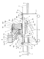
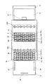
各記録ヘッド51は、図3に示すように、ヘッド支持部材100に10個のヘッド101A〜101Jを2列千鳥状に配置している。各ヘッド101は、図4に示すように、液滴を吐出する複数のノズル102を並べて配置したノズル列103を2列千鳥状に配置したノズル面104を有している。なお、記録ヘッドユニット50の構成は、これらの例に限るものではない。
As shown in FIG. 3, each
また、画像形成ユニット5は、記録ヘッドユニット50の上方に、各記録ヘッド51に所要の色のインクを供給する分岐手段である分岐部材52が配置され、分岐部材52と記録ヘッド51間は供給チューブ53にて接続されている。分岐部材52の上流側にはインクタンクユニット8のインクタンク81(図示の都合上1つのインクタンクのみ符号を付している。)が配置され、供給チューブ82を介して記録ヘッド51のディストリビュータ52に供給され、インクタンク81と記録ヘッド51の各ヘッド101との水頭差により各ヘッド101に負圧が形成される。さらに、インクタンク81の上流側にはメインタンクユニット9が配置され、メインタンク91から供給チューブ92を介してインクがインクタンク81に供給される。
In the
搬送ユニット4の下流側には用紙Pを排紙トレイ3に排紙する搬送ガイド部7が設けられている。搬送ガイド部7にて案内されて搬送される用紙Pは排紙トレイ3に排紙される。排紙トレイ3は、用紙Pの幅方向を規制する対のサイドフェンス31と用紙Pの先端を規制するエンドフェンス32を備えている。
On the downstream side of the transport unit 4, a
維持回復機構(クリーニング装置)6は、画像形成ユニット5の各記録ヘッド51に対応して、4列分のクリーニング手段61が配置され、1つのクリーニング手段61は記録ヘッド51の10個のヘッド101に対応する10個のキャップ部材62及び図示しないがワイパ部材などで構成されている。なお、キャップ部材62とは独立して上下動させることができる構成としている。さらに、クリーニング手段61の下方には、キャップ部材62でヘッドユニット100のノズル面104をキャッピング(封止)した状態でヘッド101のノズル102からインクを吸引するための吸引手段である吸引ポンプ63が配置されている。
The maintenance / recovery mechanism (cleaning device) 6 includes four rows of cleaning means 61 corresponding to each
また、この画像形成装置においては、印刷終了後、液滴を吐出する記録ヘッド51をクリーニング手段61でキャッピングした状態でノズル102からインクを吸引する場合、あるいは、記録ヘッド51のヘッドのノズル面104に付着したインクをクリーニング手段61のワイパ部材で清掃する場合は、図5にも示すように、印刷停止後、搬送ユニット4全体が搬送従動ローラ41bを支点に矢印B方向に回動し、画像形成ユニット5との間の空間を画像形成時よりも大きくすることで、画像形成ユニット5の移動スペースを確保するようにしている。このとき、クリーニング装置6上部に配置されている搬送ガイド部7の搬送ガイド板71も支点72にて矢印C方向上方に回動され、クリーニング装置6の上方が開放される。
In this image forming apparatus, after the printing is completed, when the
そして、搬送ユニット4と搬送ガイド部7がそれぞれ解放(解除)された後に、画像形成ユニット5が用紙通紙方向(矢示A方向)に移動し、クリーニング装置6上方で停止され、クリーニング手段61が上昇して各記録ヘッド51のヘッドのクリーニング動作(維持回復動作)に移行する。
Then, after the transport unit 4 and the
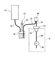
次に、この画像形成装置における記録ヘッドに対するインク供給系及びインク排出系について図6をも参照して説明する。
記録ヘッド51に供給するインクを収容するインクタンク81は、記録ヘッド51との間で所要の水頭差を持たせて配置している。この場合、インクタンク81の液面高さと記録ヘッド51の高さの差(水頭差)によって発生する記録ヘッド51のノズル面104(ノズル102のノズル面104への開口)における負圧(水頭圧)は、インクタンク81内のインクの消費によって変化する。また、インクタンク81にはタンク内を大気に通じる大気開放路83が設けられて、この大気開放路83を開閉する大気開放弁84が設けられ、通常はインクタンク81は大気開放状態にある。
Next, an ink supply system and an ink discharge system for the recording head in this image forming apparatus will be described with reference to FIG.
The
また、このインクタンク81にインクを供給するメインタンク91を設け、インクタンク81内に設けた図示しない電極ピンなどの液面センサの信号に応じてメインタンク91からインクタンク81へのインクの供給を制御して、インクタンク81におけるインク量を一定の範囲に制御している。なお、メインタンク91からインクタンク81へのインクの供給は、メインタンク91からインクタンク81へのインク供給経路(供給チューブ)92中に設けられた電磁弁などの弁手段を図示しない制御手段によって液面センサの信号に基づいて開閉制御することで行っている。
Further, a
一方、1つの記録ヘッド51の各ヘッド101に対してインク供給経路(流路)を分岐する分岐手段としての分岐部材52が配置されている。なお、分岐部材52は、図1に示すように、各記録ヘッド51y、51m、51c、51kに対してそれぞれ分岐部材52y、52m、52c、52kが配置される。
On the other hand, a branching member 52 is disposed as a branching unit that branches the ink supply path (flow path) with respect to each
そして、この分岐部52の一端部側にはインクタンク81との間に供給チューブ82が接続され、この供給チューブ82を介してインクタンク81からインクが供給される。
。
A
.
また、記録ヘッド51のヘッド101のノズル102からインクを吸引するため、クリーニング装置6は、ヘッド101のノズル面104を封止するキャップ部材62と、キャップ部材62に排インクチューブ64を介して接続された吸引手段としての吸引ポンプ63とを備えて、キャップ部材62でヘッド101のノズル面104を封止した状態で吸引ポンプ63を駆動することによってキャップ部材62内の密閉空間が負圧になってノズル102からインクが吸引排出される。
Further, in order to suck ink from the
次に、この画像形成装置の制御部の概要について図7のブロック説明図を参照して説明する。
この制御部は、この画像形成装置全体の制御を司る本発明に係る制御手段を兼ねるマイクロコンピュータ、画像メモリ、通信インタフェースなどで構成した主制御部(システムコントローラ)501を備えている。主制御部501は、外部の情報処理装置(ホスト側)などから転送される画像データ及び各種コマンド情報に基づいて用紙に画像を形成するために、印刷制御部502に印刷用データを送出する。
Next, an outline of the control unit of the image forming apparatus will be described with reference to a block diagram of FIG.
The control unit includes a main control unit (system controller) 501 including a microcomputer that also serves as a control unit according to the present invention that controls the entire image forming apparatus, an image memory, a communication interface, and the like. The
印刷制御部502は、主制御部501からの受領する印刷データ信号に基づいて、記録ヘッド51から液滴を吐出させるための圧力発生手段を駆動するためのデータを生成し、このデータの転送及び転送の確定などに必要な各種信号などをヘッドドライバ503に転送するとともに、駆動波形データ格納手段である記憶部、駆動波形のデータをD/A変換するD/A変換器及び電圧増幅器や電流増幅器等で構成される駆動波形生成部、ヘッドドライバ503に与える駆動波形を選択する選択手段を含み、1の駆動パルス(駆動信号)或いは複数の駆動パルス(駆動信号)で構成される駆動波形を生成してヘッドドライバ503に出力して、記録ヘッド51を駆動制御する。
Based on the print data signal received from the
また、主制御部501は、モータドライバ504を介して、搬送ベルト43を周回移動させる用紙送りモータ505、吸引ポンプ63を駆動制御する。
Further, the
また、主制御部501には、前述したインク液面検出手段を含むセンサ群506からの検出信号が入力され、また、操作部507との間で各種情報の入出力及び表示情報のやり取りを行う。
Further, the
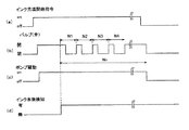
次に、このように構成したこの実施形態における制御部によるインク初期充填制御について図8に示すタイミングチャートを参照して説明する。
まず、記録ヘッド51にインクの初期充填を行うときには、クリーニング装置6のキャップ部材62によって記録ヘッドユニット50の記録ヘッド51のヘッド101のノズル面104がキャッピング(封止)された状態にある。また、インクタンク81の大気開放弁84は閉じている。
Next, ink initial filling control by the control unit in this embodiment configured as described above will be described with reference to a timing chart shown in FIG.
First, when the
ここで、図8(a)に示すように、インク充填開始指令が発生する(onになる)と、図8(b)に示すように、主制御部501は予め設定された設定時間tの間吸引ポンプ63を連続して駆動する(on)。これにより、インクタンク81から記録ヘッド51に対して連続的にインクの流れが発生して記録ヘッド51の各ヘッド101に対するインク供給が行われる。ここで、設定時間tは、吸引ポンプ63の駆動を開始した時点からインクタンク81から供給チューブ82を介して圧送されるインクが記録ヘッド51の分岐部材52を満たしてヘッド101に到達するまでの時間であり、予め実験などにより求められている。
Here, as shown in FIG. 8A, when an ink filling start command is generated (turned on), as shown in FIG. 8B, the
そして、設定時間tが経過したときから、主制御部501は吸引ポンプ63の駆動と停止を繰り返して間歇的に駆動する(on/offを繰り返す)。この間歇的な駆動は予め定めた設定回数Nnだけ行う。これにより、インクタンク81から記録ヘッド51に対して間歇的にインクの流れが発生して記録ヘッド51の各ヘッド101に対するインク供給が行われる。
Then, after the set time t has elapsed, the
このように、記録ヘッド51のヘッド101にインクが到達するまでは吸引ポンプ63を連続駆動してインクタンク81から記録ヘッド51に対して連続的なインクの流れを発生させ、記録ヘッド51にインクが到達した後は吸引ポンプ63を間歇的に駆動して間歇的なインクの流れを発生させる制御をする。
In this manner, the
したがって、記録ヘッド51にインクが到達するまでは連続的なインク供給を行って供給チューブ82、分岐部材52内の流路に短時間でインクを満たすことができる。そして、記録ヘッド51にインクが到達した後間歇的なインクの流れによって気泡を排出することができる。
Therefore, the ink can be continuously supplied until the ink reaches the
つまり、記録ヘッド内部にインクが到達する前に間欠的なインク充填を行っても気泡排出性にはあまり影響がなく、むしろ、間欠的なインク供給を行うと、インクタンクからヘッドまでインクを到達させるのに時間を要してしまうことになる。そこで、ヘッドまでインクを早く到達させるためには連続的なポンプ動作(吸引)を行い、インクがヘッドに達したときに間欠的なインク供給を行って瞬間的なインクの流れを作り出すことで気泡を確実に排出させる。 In other words, even if intermittent ink filling is performed before ink reaches the inside of the recording head, there is no significant effect on the bubble discharge performance. Rather, if ink is intermittently supplied, ink reaches from the ink tank to the head. It will take time to make it happen. Therefore, in order to quickly reach the ink to the head, a continuous pump operation (suction) is performed, and when the ink reaches the head, intermittent ink supply is performed to create an instantaneous ink flow. To ensure that it is discharged.
このように、インクを初期充填するとき、記録ヘッドにインクが到達するまではインクタンクから記録ヘッドに対して連続的なインクの流れを発生させ、記録ヘッドにインクが到達した後は間歇的なインクの流れを発生させるので、気泡排出性を維持しつつ初期充填時間を短縮することができる。 In this way, when ink is initially filled, a continuous ink flow is generated from the ink tank to the recording head until the ink reaches the recording head, and intermittently after the ink reaches the recording head. Since the ink flow is generated, the initial filling time can be shortened while maintaining the bubble discharge performance.
次に、本発明の第2実施形態について図9及び図10を参照して説明する。なお、図9は同実施形態におけるインク供給系及び排出系の模式的説明図、図10は同じく1つの記録ヘッド分の側面模式的説明図である。
ここでは、クリーニング装置6のキャップ部材62と吸引ポンプ63との間に排インクチューブ64で形成される吸引経路を開閉する開閉手段としての開閉弁(バルブ)65を設けている。また、記録ヘッドユニット50の分岐部材52と記録ヘッド51の各ヘッド101との間の供給チューブ53で形成される供給経路には、ヘッド101の流入口部分にインクの有無を検知してヘッド101にインクが到達したことを検知する透過型フォトセンサなどからなるインク有無検知手段66を設けている。なお、開閉弁65の開閉駆動は前述した第1実施形態の主制御部501によって行われ、また主制御部501にはインク有無検知手段66の検知信号が入力される。
Next, a second embodiment of the present invention will be described with reference to FIGS. FIG. 9 is a schematic explanatory view of an ink supply system and a discharge system in the same embodiment, and FIG. 10 is a schematic side view of one recording head.
Here, an opening / closing valve (valve) 65 is provided between the
次に、このように構成したこの実施形態における制御部によるインク初期充填制御について図11に示すタイミングチャートを参照して説明する。
まず、記録ヘッド51にインクの初期充填を行うときには、クリーニング装置6のキャップ部材62によって記録ヘッドユニット50の記録ヘッド51の各ヘッド101のノズル面104がキャッピング(封止)された状態にある。また、インクタンク81の大気開放弁84は閉じている。
Next, ink initial filling control by the control unit in this embodiment configured as described above will be described with reference to a timing chart shown in FIG.
First, when the ink is initially filled in the
ここで、図11(a)に示すように、インク充填開始指令が発生する(onになる)と、図11(b)に示すように、主制御部501は開閉弁(バルブ)65を開くとともに、図11(c)に示すように、吸引ポンプ63を連続して駆動する(onにする)。これにより、インクタンク81から記録ヘッド51に対して連続的にインクの流れが発生して記録ヘッド51の各ヘッド101に対するインク供給が行われる。
Here, as shown in FIG. 11A, when an ink filling start command is generated (turned on), the
そして、図11(d)に示すように、インク有無検知手段66が記録ヘッド51のヘッド101に流入口部分に到達したことが検知された時から、図11(b)に示すように、主制御部501は開閉弁65の開閉を繰り返す。このとき、吸引ポンプ63は連続的に駆動されたままであるので、開閉弁65が開閉されることで、インクタンク81から記録ヘッド51に対して間歇的にインクの流れが発生して記録ヘッド51の各ヘッド101に対するインク供給が行われる。開閉弁65の開閉駆動は予め定めた設定回数Nnだけ行う。
Then, as shown in FIG. 11 (d), from the time when it is detected that the ink presence /
このように、記録ヘッド51のヘッド101にインクが到達するまでは吸引ポンプ63を連続駆動したまま、開閉弁65を開いてインクタンク81から記録ヘッド51に対して連続的なインクの流れを発生させ、記録ヘッド51にインクが到達した後は吸引ポンプ63を連続駆動したまま開閉弁65の開閉を繰り返して間歇的なインクの流れを発生させる制御をする。
In this way, the
したがって、記録ヘッド51にインクが到達するまでは連続的なインク供給を行って供給チューブ82、分岐部材52内の流路に短時間でインクを満たすことができる。そして、記録ヘッド51にインクが到達した後間歇的なインクの流れによって気泡を排出することができる。
Therefore, the ink can be continuously supplied until the ink reaches the
つまり、前述したように、記録ヘッド内部にインクが到達する前に間欠的なインク充填を行っても気泡排出性にはあまり影響がなく、むしろ、間欠的なインク供給を行うと、インクタンクからヘッドまでインクを到達させるのに時間を要してしまうことになる。そこで、ヘッドまでインクを早く到達させるためには連続的な吸引動作を行い、インクがヘッドに達したときに間欠的なインク供給を行って瞬間的なインクの流れを作り出すことで気泡を確実に排出させる。 In other words, as described above, even if intermittent ink filling is performed before the ink reaches the inside of the recording head, the bubble discharge performance is not significantly affected. It takes time to make the ink reach the head. Therefore, in order to quickly reach the ink to the head, a continuous suction operation is performed, and when the ink reaches the head, intermittent ink supply is performed to create an instantaneous ink flow, thereby ensuring air bubbles. Let it drain.
このように、インクを初期充填するとき、記録ヘッドにインクが到達するまではインクタンクから記録ヘッドに対して連続的なインクの流れを発生させ、記録ヘッドにインクが到達した後は間歇的なインクの流れを発生させるので、気泡排出性を維持しつつ初期充填時間を短縮することができる。 In this way, when ink is initially filled, a continuous ink flow is generated from the ink tank to the recording head until the ink reaches the recording head, and intermittently after the ink reaches the recording head. Since the ink flow is generated, the initial filling time can be shortened while maintaining the bubble discharge performance.
なお、上記実施形態ではライン型画像形成装置に適用した例で説明しているが、シリアル型画像形成装置にも同様に適用することができる。 In the above-described embodiment, an example in which the present invention is applied to a line-type image forming apparatus has been described.
1…装置本体
4…搬送ユニット(搬送部)
5…画像形成ユニット
6…クリーニング装置(維持回復機構)
7…搬送ガイド部
8…インクタンクユニット
9…メインタンクユニット
50…記録ヘッドユニット
51…記録ヘッド
54…分岐部材
62…キャップ
63…吸引ポンプ
64…排インクチューブ(吸引経路)
65…開閉弁
66…インク有無検知手段
81…インクタンク
91…メインタンク
101…ヘッド
DESCRIPTION OF SYMBOLS 1 ... Apparatus main body 4 ... Conveyance unit (conveyance part)
5. Image forming unit 6. Cleaning device (maintenance and recovery mechanism)
DESCRIPTION OF
65 ... Open /
Claims (3)
前記記録ヘッドに供給するインクを収容するインクタンクと、
前記記録ヘッドのノズル面を封止するキャップ部材及びこのキャップ部材に接続された吸引手段と、
前記キャップ部材で前記記録ヘッドのノズル面を封止した状態で、前記吸引手段を駆動して前記記録ヘッドに前記インクタンクからインクを初期充填するとき、前記記録ヘッドにインクが到達するまでは前記吸引手段を連続駆動して前記インクタンクから前記記録ヘッドに対して連続的なインクの流れを発生させ、前記記録ヘッドにインクが到達した後は前記吸引手段を間歇的に駆動して間歇的なインクの流れを発生させる制御をする制御手段と、を備えている
ことを特徴とする画像形成装置。 A recording head for discharging droplets;
An ink tank for storing ink to be supplied to the recording head;
A cap member for sealing the nozzle surface of the recording head, and suction means connected to the cap member;
In a state where the nozzle surface of the recording head is sealed with the cap member, when the suction unit is driven to initially fill the recording head with ink from the ink tank, until the ink reaches the recording head, The suction unit is continuously driven to generate a continuous ink flow from the ink tank to the recording head, and after the ink reaches the recording head, the suction unit is intermittently driven to intermittently An image forming apparatus comprising: a control unit that performs control to generate an ink flow.
前記記録ヘッドに供給するインクを収容するインクタンクと、
前記記録ヘッドのノズル面を封止するキャップ部材及びこのキャップ部材に接続された吸引手段と、
前記キャップ部材と吸引手段との間の吸引経路を開閉する開閉手段と、
前記キャップ部材で前記記録ヘッドのノズル面を封止した状態で、前記吸引手段を駆動して前記記録ヘッドに前記インクタンクからインクを初期充填するとき、前記吸引手段を連続駆動しながら、前記記録ヘッドにインクが到達するまでは前記開閉手段を開いて前記インクタンクから前記記録ヘッドに対して連続的なインクの流れを発生させ、前記記録ヘッドにインクが到達した後は前記開閉手段の開閉を繰り返して間歇的なインクの流れを発生させる制御をする制御手段と、を備えている
ことを特徴とする画像形成装置。 A recording head for discharging droplets;
An ink tank for storing ink to be supplied to the recording head;
A cap member for sealing the nozzle surface of the recording head, and suction means connected to the cap member;
Opening and closing means for opening and closing a suction path between the cap member and the suction means;
When the suction unit is driven and the recording head is initially filled with ink from the ink tank with the cap member sealed with the nozzle surface of the recording head, the recording unit is continuously driven while the recording unit is driven. Until the ink reaches the head, the opening / closing means is opened to generate a continuous ink flow from the ink tank to the recording head, and after the ink reaches the recording head, the opening / closing means is opened / closed. An image forming apparatus comprising: a control unit that performs control to repeatedly generate an intermittent ink flow.
Priority Applications (1)
| Application Number | Priority Date | Filing Date | Title |
|---|---|---|---|
| JP2008210367A JP5107826B2 (en) | 2008-08-19 | 2008-08-19 | Image forming apparatus |
Applications Claiming Priority (1)
| Application Number | Priority Date | Filing Date | Title |
|---|---|---|---|
| JP2008210367A JP5107826B2 (en) | 2008-08-19 | 2008-08-19 | Image forming apparatus |
Publications (2)
| Publication Number | Publication Date |
|---|---|
| JP2010046806A true JP2010046806A (en) | 2010-03-04 |
| JP5107826B2 JP5107826B2 (en) | 2012-12-26 |
Family
ID=42064331
Family Applications (1)
| Application Number | Title | Priority Date | Filing Date |
|---|---|---|---|
| JP2008210367A Expired - Fee Related JP5107826B2 (en) | 2008-08-19 | 2008-08-19 | Image forming apparatus |
Country Status (1)
| Country | Link |
|---|---|
| JP (1) | JP5107826B2 (en) |
Cited By (2)
| Publication number | Priority date | Publication date | Assignee | Title |
|---|---|---|---|---|
| JP2013052583A (en) * | 2011-09-04 | 2013-03-21 | Ricoh Co Ltd | Image forming apparatus and liquid filling method in the image forming apparatus |
| JP2015100974A (en) * | 2013-11-22 | 2015-06-04 | キヤノン株式会社 | Recording apparatus and bubble discharge method therefor |
Citations (4)
| Publication number | Priority date | Publication date | Assignee | Title |
|---|---|---|---|---|
| JPH03151244A (en) * | 1989-11-08 | 1991-06-27 | Fuji Xerox Co Ltd | Ink filling method for ink-jet printer |
| JP2000085153A (en) * | 1998-07-15 | 2000-03-28 | Seiko Epson Corp | Ink-jet recording apparatus and method for initial filling therefor |
| JP2006015631A (en) * | 2004-07-02 | 2006-01-19 | Seiko Epson Corp | Droplet ejector and method for filling droplet ejection head with liquid |
| JP2006198846A (en) * | 2005-01-19 | 2006-08-03 | Seiko Epson Corp | Filling method, and liquid delivering apparatus |
-
2008
- 2008-08-19 JP JP2008210367A patent/JP5107826B2/en not_active Expired - Fee Related
Patent Citations (4)
| Publication number | Priority date | Publication date | Assignee | Title |
|---|---|---|---|---|
| JPH03151244A (en) * | 1989-11-08 | 1991-06-27 | Fuji Xerox Co Ltd | Ink filling method for ink-jet printer |
| JP2000085153A (en) * | 1998-07-15 | 2000-03-28 | Seiko Epson Corp | Ink-jet recording apparatus and method for initial filling therefor |
| JP2006015631A (en) * | 2004-07-02 | 2006-01-19 | Seiko Epson Corp | Droplet ejector and method for filling droplet ejection head with liquid |
| JP2006198846A (en) * | 2005-01-19 | 2006-08-03 | Seiko Epson Corp | Filling method, and liquid delivering apparatus |
Cited By (2)
| Publication number | Priority date | Publication date | Assignee | Title |
|---|---|---|---|---|
| JP2013052583A (en) * | 2011-09-04 | 2013-03-21 | Ricoh Co Ltd | Image forming apparatus and liquid filling method in the image forming apparatus |
| JP2015100974A (en) * | 2013-11-22 | 2015-06-04 | キヤノン株式会社 | Recording apparatus and bubble discharge method therefor |
Also Published As
| Publication number | Publication date |
|---|---|
| JP5107826B2 (en) | 2012-12-26 |
Similar Documents
| Publication | Publication Date | Title |
|---|---|---|
| JP5327446B2 (en) | Image forming apparatus | |
| JP4816261B2 (en) | Droplet discharge device | |
| JP2016087976A (en) | Image forming apparatus | |
| JP5790202B2 (en) | Image forming apparatus | |
| JP5402033B2 (en) | Image forming apparatus | |
| JP5494212B2 (en) | Ink supply device | |
| JP5636823B2 (en) | Image forming apparatus | |
| JP2010125740A (en) | Image forming apparatus | |
| JP2010137388A (en) | Image forming apparatus | |
| JP5107826B2 (en) | Image forming apparatus | |
| JP2007313654A (en) | Inkjet printer | |
| JP5277870B2 (en) | Image forming apparatus | |
| JP5359678B2 (en) | Image forming apparatus | |
| JP2008037055A (en) | Liquid droplet ejection apparatus | |
| JP5703721B2 (en) | Image forming apparatus | |
| JP5365092B2 (en) | Image forming apparatus | |
| JPH10202922A (en) | Ink jet recorder | |
| JP5515634B2 (en) | Image forming apparatus | |
| JP5272524B2 (en) | Image forming apparatus | |
| JP2011143614A (en) | Image forming apparatus | |
| JP5803459B2 (en) | Image forming apparatus | |
| JP2010006008A (en) | Recording unit, ink-jet recording device, control program, and storage medium | |
| JP2010052194A (en) | Image forming apparatus | |
| JP2007261158A (en) | Inkjet printer and printing method | |
| JP2017081020A (en) | Liquid discharging device |
Legal Events
| Date | Code | Title | Description |
|---|---|---|---|
| A621 | Written request for application examination |
Free format text: JAPANESE INTERMEDIATE CODE: A621 Effective date: 20110607 |
|
| A977 | Report on retrieval |
Free format text: JAPANESE INTERMEDIATE CODE: A971007 Effective date: 20120801 |
|
| A131 | Notification of reasons for refusal |
Free format text: JAPANESE INTERMEDIATE CODE: A131 Effective date: 20120807 |
|
| A521 | Written amendment |
Free format text: JAPANESE INTERMEDIATE CODE: A523 Effective date: 20120901 |
|
| TRDD | Decision of grant or rejection written | ||
| A01 | Written decision to grant a patent or to grant a registration (utility model) |
Free format text: JAPANESE INTERMEDIATE CODE: A01 Effective date: 20121002 |
|
| A01 | Written decision to grant a patent or to grant a registration (utility model) |
Free format text: JAPANESE INTERMEDIATE CODE: A01 |
|
| A61 | First payment of annual fees (during grant procedure) |
Free format text: JAPANESE INTERMEDIATE CODE: A61 Effective date: 20121004 |
|
| R150 | Certificate of patent or registration of utility model |
Ref document number: 5107826 Country of ref document: JP Free format text: JAPANESE INTERMEDIATE CODE: R150 Free format text: JAPANESE INTERMEDIATE CODE: R150 |
|
| FPAY | Renewal fee payment (event date is renewal date of database) |
Free format text: PAYMENT UNTIL: 20151012 Year of fee payment: 3 |
|
| LAPS | Cancellation because of no payment of annual fees |