JP2010044407A - Method for measuring focal length of condensing hologram array - Google Patents
Method for measuring focal length of condensing hologram array Download PDFInfo
- Publication number
- JP2010044407A JP2010044407A JP2009237096A JP2009237096A JP2010044407A JP 2010044407 A JP2010044407 A JP 2010044407A JP 2009237096 A JP2009237096 A JP 2009237096A JP 2009237096 A JP2009237096 A JP 2009237096A JP 2010044407 A JP2010044407 A JP 2010044407A
- Authority
- JP
- Japan
- Prior art keywords
- hologram
- array
- condensing
- focal length
- light
- Prior art date
- Legal status (The legal status is an assumption and is not a legal conclusion. Google has not performed a legal analysis and makes no representation as to the accuracy of the status listed.)
- Granted
Links
Images

Landscapes
- Diffracting Gratings Or Hologram Optical Elements (AREA)
Abstract
Description
本発明は、集光性ホログラムアレーに関し、特に、ホログラムカラーフィルター等の集光性要素ホログラムのアレーに関するものである。 The present invention relates to a condensing hologram array, and more particularly to an array of condensing element holograms such as hologram color filters.
本出願人は、特願平5−12170号等において、液晶表示用バックライト等の利用効率を大幅に向上させるために、ホログラムを利用したカラーフィルターを提案した。このホログラムカラーフィルターは、基本的には、特定波長で特定の斜めの入射角で入射した平行光を特定の焦点距離の位置に収束するように回折する透過型の集光性要素ホログラムのアレーからなるものである。 In Japanese Patent Application No. 5-12170, the present applicant has proposed a color filter using a hologram in order to greatly improve the utilization efficiency of a backlight for liquid crystal display. This hologram color filter basically consists of an array of transmissive condensing element holograms that diffract parallel light incident at a specific wavelength and at a specific oblique incident angle so as to converge at a specific focal length. It will be.
また、マイクロレンズアレーの各マイクロレンズをマイクロホログラムレンズとしてマイクロホログラムレンズアレーを構成することもよく知られている。 It is also well known to construct a micro-hologram lens array using each micro-lens of the micro-lens array as a micro-hologram lens.
このような集光性ホログラムアレーを原版として同様の特性のホログラムアレーをホログラム複製方法により複製するには、例えば、計算機ホログラム(CGH)として第1原版を作製し、次いで、その第1原版をホログラム複製方法により複製してホログラム原版を作製し、そのホログラム原版から最終製品を同様のホログラム複製方法により複製して作製する方法がとられている(例えば、特願平7−260035号)。 In order to replicate a hologram array having the same characteristics using such a condensing hologram array as a master by a hologram duplicating method, for example, a first master is prepared as a computer generated hologram (CGH), and then the first master is used as a hologram. A method has been adopted in which a hologram master is produced by duplication by a duplication method, and a final product is produced by duplication from the hologram master by a similar hologram duplication method (for example, Japanese Patent Application No. 7-260035).
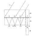
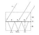
上記のようなホログラムカラーフィルターは、例えば液晶表示装置用のカラーフィルターとして構成する場合、図4に断面を示すように、ホログラムカラーフィルター11自身は斜めの入射の平行光1を正面方向に集光する要素ホログラムaのアレーからなり、そのホログラムカラーフィルター11をガラス板12と13の間に挟んで、ガラス板13の表面近傍に斜めの入射の平行光(G光)1の集光位置bがくるように構成して使用する。
When the hologram color filter as described above is configured as a color filter for a liquid crystal display device, for example, the
ここで、界面による不要な反射を防止するために、通常、ガラス板12、13とホログラムカラーフィルター11の屈折率は略同じに選択される。
Here, in order to prevent unnecessary reflection by the interface, the refractive indexes of the
ところで、上記したように、このようなホログラムカラーフィルター11はホログラム複製方法により複製して製造されるが、設計通りの焦点距離fを有していない場合に、ホログラムカラーフィルター11によってバックライトがRGB3色に分散分光される位置が所定位置からずれるため、所望の特性が得られない。
By the way, as described above, such a
そこで、最終製品等の焦点距離fを測定検査することが重要になる。図4のような配置で焦点距離fを測定するには、ホログラムカラーフィルター11の面(主面)を検出する必要があるが、上記のように、ガラス板12、13、ホログラムカラーフィルター11の屈折率は略同じであるため、フレネル反射によりホログラムカラーフィルター11の面(主面)を検出することは困難である。
Therefore, it is important to measure and inspect the focal length f of the final product or the like. In order to measure the focal length f with the arrangement as shown in FIG. 4, it is necessary to detect the surface (main surface) of the
本発明はこのような現状に鑑みてなされたものであり、その目的は、ホログラムカラーフィルター等の集光性ホログラムアレーのホログラム面を容易に検出できるようにした集光性ホログラムアレーの焦点距離の測定方法を提供することである。 The present invention has been made in view of such a current situation, and an object of the present invention is to determine the focal length of a condensing hologram array that can easily detect the hologram surface of a condensing hologram array such as a hologram color filter. It is to provide a measurement method.
上記目的を達成する本発明の集光性ホログラムアレーの焦点距離の測定方法は、特定波長で特定の入射角で入射した平行光を特定の焦点距離の位置に収束するように回折する透過型の集光性要素ホログラムのアレーからなる集光性ホログラムアレー焦点距離の測定方法において、前記アレーの欄外あるいは前記アレーに重畳してホログラムミラーを設け、前記ホログラムミラーに測定光を照射してその反射光を検出することにより前記集光性ホログラムアレーの面を検出し、検出された前記集光性ホログラムアレーの面の位置と前記集光性要素ホログラムの集光位置とから前記集光性要素ホログラムの焦点距離を求めることを特徴とする方法である。 The method of measuring the focal length of the condensing hologram array of the present invention that achieves the above object is a transmission type that diffracts parallel light incident at a specific wavelength and at a specific incident angle so as to converge at a specific focal length. In the method of measuring a focal length of a condensing hologram array comprising an array of condensing element holograms, a hologram mirror is provided outside the array or superimposed on the array, and the reflected light is irradiated by measuring light on the hologram mirror. The surface of the condensing hologram array is detected by detecting the position of the condensing element hologram from the detected position of the condensing hologram array surface and the condensing position of the condensing element hologram. This is a method characterized by obtaining a focal length.
この場合に、そのホログラムミラーは、干渉縞がホログラム面と平行に記録されてなる体積ホログラムからなるものである。 In this case, the hologram mirror is composed of a volume hologram in which interference fringes are recorded in parallel with the hologram surface.
また、集光性ホログラムアレーは透明板間に接着挟持された形態とすることができる。 Further, the condensing hologram array can be in a form of being sandwiched between transparent plates.
なお、集光性要素ホログラムが斜めの入射角で入射した白色平行光を分散分光するホログラムからなるものとしてもよい。 The condensing element hologram may be a hologram that disperses and splits white parallel light incident at an oblique incident angle.
本発明においては、アレーの欄外あるいはアレーの一部に重畳してホログラムミラーを備えているので、そのホログラムミラーに測定光を照射し、反射光を検出することにより容易にホログラム面を検出することができ、集光性ホログラムアレーの焦点距離を精密に測定することができ、集光性ホログラムアレーの焦点距離等が所定の値になるように作製されているか否かを検査することができる。 In the present invention, since the hologram mirror is provided so as to be superimposed on the outside of the array or a part of the array, the hologram surface can be easily detected by irradiating the hologram mirror with measurement light and detecting the reflected light. Thus, the focal length of the condensing hologram array can be accurately measured, and it can be inspected whether or not the focal length of the condensing hologram array is made to be a predetermined value.
以下、本発明の集光性ホログラムアレーの焦点距離の測定方法を実施例に基づいて説明する。 Hereinafter, a method for measuring the focal length of the condensing hologram array of the present invention will be described based on examples.
図1に、本発明による集光性ホログラムアレーの1実施例の断面図を示す。この実施例においては、集光性ホログラムアレーとしては、斜めの入射の平行光1を正面方向に集光する要素ホログラムaのアレーからなるホログラムカラーフィルター11としている。このホログラムカラーフィルター11は、屈折率が略等しいガラス板12と13の間に接着挟持されている。この場合、ホログラムカラーフィルター11には、欄外あるいは要素ホログラムaと多重記録されて(図1の場合は、欄外に)、ホログラムミラーcが同じフォトポリマー等のホログラム感材中に記録されている。
FIG. 1 shows a cross-sectional view of one embodiment of a condensing hologram array according to the present invention. In this embodiment, the condensing hologram array is a
ここで、ホログラムミラーcは、体積型ホログラム感材中に干渉縞がホログラム面と平行に記録されてなる体積ホログラムであり、ブラッグ条件を満足する入射光を正反射する性質を持っている。 Here, the hologram mirror c is a volume hologram in which interference fringes are recorded in parallel with the hologram surface in a volume hologram sensitive material, and has a property of regularly reflecting incident light that satisfies the Bragg condition.
このように、本発明においては、集光性ホログラムアレー11の同じ記録材料中の一部に干渉縞がホログラム面と平行に記録されてなるホログラムミラーcが記録されているの
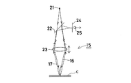
で、このホログラムミラーcを基準面として、例えば公知の適当な測定装置15を用いて、その測定装置15から測定光16をこのホログラムミラーcに照射し、ホログラムミラーcからの反射光17を検出することにより、ホログラムミラーcの面、すなわち、集光性ホログラムアレー11の面を検出することができる。その検出された集光性ホログラムアレー11の面の位置と他の方法で測定された集光位置bとから要素ホログラムaの焦点距離fを求めることができ、その焦点距離fが所定の値に一致するか否かが検査される。
Thus, in the present invention, the hologram mirror c in which the interference fringes are recorded in parallel with the hologram surface is recorded on a part of the same recording material of the
ここで、測定装置15の1つの方式を図2を参照にして説明する。この測定装置15は、光源21と、その光源21からの発散光を収束光に変換して測定光16としてホログラムミラーcに照射する対物レンズ23と、対物レンズ23を経て戻ってきたホログラムミラーcからの反射光17を入射光路から分離するハーフミラー22と、ハーフミラー22で分離された反射光17の集光点近傍に配置されたピンホール24と、ピンホール24の射出側に配置された光電検出器25とからなり、対物レンズ23は光軸方向に移動調節可能になっている。
Here, one method of the
このような配置において、光源21からの発散光は対物レンズ23で収束光16に変換され、ホログラムミラーcに入射する。収束光16の収束点が丁度ホログラムミラーc上にあるとき、反射光17は対物レンズ23とハーフミラー22を経てピンホール24上に収束するようにピンホール24の位置が調節されている。
In such an arrangement, divergent light from the
したがって、対物レンズ23に対してホログラムミラーcが任意の位置にあるとき、対物レンズ23の光軸方向の位置を調節してピンホール24を通って光電検出器25に達する光量が最大になる対物レンズ23の位置を読み取れば、対物レンズ23に対するホログラムミラーcの相対位置が求まる。
Therefore, when the hologram mirror c is at an arbitrary position with respect to the
もちろん、測定光16をホログラムミラーcに照射し、ホログラムミラーcからの反射光17を検出することにより、ホログラムミラーcの面の位置を検出する測定装置15としては、上記の方式のものに限定されず、種々の公知の方式のものが使用できる。
Of course, the
ところで、要素ホログラムaのアレーからなる集光性ホログラムアレーを記録した同じホログラム11の欄外あるいは要素ホログラムaに多重化してホログラムミラーcを記録する方法の1例を図3に示す。この方法は、集光性ホログラムアレー11をCGHアレー原版31からホログラム複製法により複製して作製する場合に、同時にホログラムミラーcを記録する方法である。
By the way, FIG. 3 shows an example of a method for recording the hologram mirror c by multiplexing the outside of the
CGHアレー原版31のレリーフ面に密着あるいは若干離間してフォトポリマー等のホログラム感材32を配置し、また、そのCGHアレー原版31側とは反対側に光吸収ガラス板あるいは反射防止膜を表面に設けて反射光をなくしたガラス板36を配置する。このような配置で、複製用の所定の波長の複製照明光33を所定の入射角でCGHアレー原版31の裏面(レリーフ面と反対側の面)から入射させ、CGHアレー原版31の各要素ホログラムによって回折された回折光35と直進透過光34とをホログラム感材32中で干渉させて集光性ホログラムアレー11を複製する。ホログラム感材32を透過した回折光35と直進透過光34はガラス板36で反射されて戻ることがないので、ホログラム感材32中に不要干渉縞が記録されることはない。
A hologram
この際、光吸収ガラス板あるいは反射防止ガラス板36のホログラムミラーcを記録する領域に相当する表面に反射膜37を設けておき、上記のCGHアレー原版31の複製と同時あるいはその前後に、複製照明光33とは別の平行光38をこの反射膜37に向けて入射させ、反射膜37からの反射光39と入射光38とをホログラム感材32中で干渉させることにより、ホログラム面に平行な干渉縞からなるホログラムミラーcが記録される
。
At this time, a
以上は、第1原版作製段階で同時にホログラムミラーcを記録するが、この第1原版からホログラム原版を複製する段階、あるいは、そのホログラム原版から最終製品を複製する段階で同時にホログラムミラーcを記録するようにしてもよい。 As described above, the hologram mirror c is simultaneously recorded in the first original plate production stage. However, the hologram mirror c is simultaneously recorded in the stage in which the hologram original plate is duplicated from the first original plate or the final product is duplicated from the hologram original plate. You may do it.
さて、上記のホログラムミラーcの記録において、複製照明光33とホログラムミラー記録用の光38とは波長が同じでも異なっていてもよいが、異なる場合には、ホログラム感材32はその両波長の光に感度を持つものを用いる必要がある。
In the recording of the hologram mirror c described above, the
また、特に、複製照明光33とホログラムミラー記録用の光38に同じ波長を持つものを用いる場合(異なる波長の場合でも同様であるが)、得られたホログラムミラーcが測定装置15からの垂直入射の測定光16を反射するブラッグ条件を満足しない場合がある。このような場合には、上記のようにして得られたホログラム面に平行な干渉縞の間隔を膨潤により広げたり、収縮により狭めたりするカラーチューニングの手法によりブラッグの反射条件を満足するようにするとよい。
In particular, when the
以上、本発明の集光性ホログラムアレーを実施例に基づいて説明してきが、本発明はこれら実施例に限定されず種々の変形が可能である。 As mentioned above, although the condensing hologram array of this invention has been demonstrated based on the Example, this invention is not limited to these Examples, A various deformation | transformation is possible.
以上の説明から明らかなように、本発明の集光性ホログラムアレーの焦点距離の測定方法によると、アレーの欄外あるいはアレーの一部に重畳してホログラムミラーを備えているので、そのホログラムミラーに測定光を照射し、反射光を検出することにより容易にホログラム面を検出することができ、集光性ホログラムアレーの焦点距離を精密に測定することができ、集光性ホログラムアレーの焦点距離等が所定の値になるように作製されているか否かを検査することができる。 As is clear from the above description, according to the method for measuring the focal length of the condensing hologram array of the present invention, the hologram mirror is provided so as to be superimposed on the outside of the array or a part of the array. By irradiating the measurement light and detecting the reflected light, the hologram surface can be easily detected, the focal length of the condensing hologram array can be accurately measured, the focal length of the condensing hologram array, etc. It can be inspected whether or not it is made to have a predetermined value.
a…要素ホログラム
b…集光位置
c…ホログラムミラー
11…ホログラムカラーフィルター(集光性ホログラムアレー)
12、13…ガラス板
15…測定装置
16…測定光
17…反射光
21…光源
22…ハーフミラー
23…対物レンズ
24…ピンホール
25…光電検出器
31…CGHアレー原版
32…ホログラム感材
33…複製照明光
34…直進透過光
35…回折光
36…光吸収ガラス板、反射防止膜を表面に設けて反射光をなくしたガラス板
37…反射膜
38…平行光
39…反射光
a ... element hologram b ... condensing position c ...
DESCRIPTION OF
Claims (4)
Priority Applications (1)
| Application Number | Priority Date | Filing Date | Title |
|---|---|---|---|
| JP2009237096A JP4761085B2 (en) | 2009-10-14 | 2009-10-14 | Method for measuring focal length of condensing hologram array |
Applications Claiming Priority (1)
| Application Number | Priority Date | Filing Date | Title |
|---|---|---|---|
| JP2009237096A JP4761085B2 (en) | 2009-10-14 | 2009-10-14 | Method for measuring focal length of condensing hologram array |
Related Parent Applications (1)
| Application Number | Title | Priority Date | Filing Date |
|---|---|---|---|
| JP37272699A Division JP4680343B2 (en) | 1999-12-28 | 1999-12-28 | Condensing hologram array |
Publications (2)
| Publication Number | Publication Date |
|---|---|
| JP2010044407A true JP2010044407A (en) | 2010-02-25 |
| JP4761085B2 JP4761085B2 (en) | 2011-08-31 |
Family
ID=42015776
Family Applications (1)
| Application Number | Title | Priority Date | Filing Date |
|---|---|---|---|
| JP2009237096A Expired - Fee Related JP4761085B2 (en) | 2009-10-14 | 2009-10-14 | Method for measuring focal length of condensing hologram array |
Country Status (1)
| Country | Link |
|---|---|
| JP (1) | JP4761085B2 (en) |
Citations (3)
| Publication number | Priority date | Publication date | Assignee | Title |
|---|---|---|---|---|
| JPH05157532A (en) * | 1991-11-20 | 1993-06-22 | Canon Inc | Computer hologram for measurement and measuring method using same |
| JPH1055129A (en) * | 1996-08-09 | 1998-02-24 | Dainippon Printing Co Ltd | Method for duplicating hologram array |
| JPH11291380A (en) * | 1998-04-10 | 1999-10-26 | Dainippon Printing Co Ltd | Volumetric hologram laminate and label for manufacturing volumetric hologram laminate |
-
2009
- 2009-10-14 JP JP2009237096A patent/JP4761085B2/en not_active Expired - Fee Related
Patent Citations (3)
| Publication number | Priority date | Publication date | Assignee | Title |
|---|---|---|---|---|
| JPH05157532A (en) * | 1991-11-20 | 1993-06-22 | Canon Inc | Computer hologram for measurement and measuring method using same |
| JPH1055129A (en) * | 1996-08-09 | 1998-02-24 | Dainippon Printing Co Ltd | Method for duplicating hologram array |
| JPH11291380A (en) * | 1998-04-10 | 1999-10-26 | Dainippon Printing Co Ltd | Volumetric hologram laminate and label for manufacturing volumetric hologram laminate |
Also Published As
| Publication number | Publication date |
|---|---|
| JP4761085B2 (en) | 2011-08-31 |
Similar Documents
| Publication | Publication Date | Title |
|---|---|---|
| JP4433355B2 (en) | Production method of transmission hologram | |
| US9785114B2 (en) | Method and device for the layered production of thin volume grid stacks, and beam combiner for a holographic display | |
| JP2009544015A5 (en) | ||
| FR2726641A1 (en) | METHOD AND DEVICE FOR PROFILING SURFACES USING DIFFRACTION OPTICS | |
| CN107561007B (en) | Thin film measuring device and method | |
| JP4181119B2 (en) | Interference fringe pattern discriminator for oblique incidence interferometer | |
| Moothanchery et al. | Studies of shrinkage as a result of holographic recording in acrylamide-based photopolymer film | |
| Márquez et al. | Generation of diffractive optical elements onto a photopolymer using a liquid crystal display | |
| US7710623B2 (en) | Security hologram, method of recording same, and method of using same wherein the holographic imaging includes a single coherent beam of electromagnetic radiation in combination with a Lloyd's mirror to provide both reference and object beams | |
| JP4761085B2 (en) | Method for measuring focal length of condensing hologram array | |
| JP4680343B2 (en) | Condensing hologram array | |
| KR20140027812A (en) | Phase mask and holographic recording apparatus employing the same | |
| CN108562225A (en) | Reflective railway digital holographic apparatus and method altogether based on light splitting pupil | |
| Almoro et al. | Wavefront sensing using speckles with fringe compensation | |
| JP4324507B2 (en) | Vibration measuring device | |
| Andersen et al. | Holographic wavefront sensor: fast sensing, no computing | |
| TW312757B (en) | ||
| JPH1055129A (en) | Method for duplicating hologram array | |
| Wang et al. | Single-Shot Common-Path Off-Axis Dual-Wavelength Digital Holographic Microscopy Based on Two-Dimensional Grating Diffraction | |
| CN115060740B (en) | Surface defect detection device and method based on off-axis illumination structure | |
| RU181211U1 (en) | DEVICE FOR RECORDING AND TESTING HOLOGRAPHIC VOLUME REFLECTIVE GRILLES | |
| Lahijani | MASTERARBEIT/MASTER’S THESIS | |
| JP4569991B2 (en) | Method for measuring optical characteristics of hologram | |
| Krasin et al. | Development of the methods of holographic optics for wavefront control in photonic systems | |
| JP2899688B2 (en) | Hologram interferometer for cylindrical surface inspection |
Legal Events
| Date | Code | Title | Description |
|---|---|---|---|
| A131 | Notification of reasons for refusal |
Free format text: JAPANESE INTERMEDIATE CODE: A131 Effective date: 20110223 |
|
| A521 | Written amendment |
Free format text: JAPANESE INTERMEDIATE CODE: A523 Effective date: 20110413 |
|
| A01 | Written decision to grant a patent or to grant a registration (utility model) |
Free format text: JAPANESE INTERMEDIATE CODE: A01 Effective date: 20110511 |
|
| A01 | Written decision to grant a patent or to grant a registration (utility model) |
Free format text: JAPANESE INTERMEDIATE CODE: A01 |
|
| A61 | First payment of annual fees (during grant procedure) |
Free format text: JAPANESE INTERMEDIATE CODE: A61 Effective date: 20110524 |
|
| FPAY | Renewal fee payment (event date is renewal date of database) |
Free format text: PAYMENT UNTIL: 20140617 Year of fee payment: 3 |
|
| R150 | Certificate of patent or registration of utility model |
Free format text: JAPANESE INTERMEDIATE CODE: R150 |
|
| LAPS | Cancellation because of no payment of annual fees |