JP4433355B2 - Production method of transmission hologram - Google Patents
Production method of transmission hologram Download PDFInfo
- Publication number
- JP4433355B2 JP4433355B2 JP2000203402A JP2000203402A JP4433355B2 JP 4433355 B2 JP4433355 B2 JP 4433355B2 JP 2000203402 A JP2000203402 A JP 2000203402A JP 2000203402 A JP2000203402 A JP 2000203402A JP 4433355 B2 JP4433355 B2 JP 4433355B2
- Authority
- JP
- Japan
- Prior art keywords
- hologram
- light
- photosensitive material
- transmission
- illumination light
- Prior art date
- Legal status (The legal status is an assumption and is not a legal conclusion. Google has not performed a legal analysis and makes no representation as to the accuracy of the status listed.)
- Expired - Fee Related
Links
- 230000005540 biological transmission Effects 0.000 title claims description 93
- 238000004519 manufacturing process Methods 0.000 title claims description 41
- 239000000463 material Substances 0.000 claims description 133
- 238000005286 illumination Methods 0.000 claims description 110
- 238000000034 method Methods 0.000 claims description 24
- 230000031700 light absorption Effects 0.000 claims description 19
- 238000002834 transmittance Methods 0.000 claims description 8
- 230000010076 replication Effects 0.000 claims description 6
- 230000001427 coherent effect Effects 0.000 claims description 4
- 230000002452 interceptive effect Effects 0.000 claims description 2
- 238000010586 diagram Methods 0.000 description 8
- 125000006850 spacer group Chemical group 0.000 description 4
- 239000012467 final product Substances 0.000 description 3
- 230000008569 process Effects 0.000 description 3
- 238000003491 array Methods 0.000 description 2
- 230000003362 replicative effect Effects 0.000 description 2
- 239000000758 substrate Substances 0.000 description 2
- 238000010521 absorption reaction Methods 0.000 description 1
- 230000009471 action Effects 0.000 description 1
- 239000006185 dispersion Substances 0.000 description 1
- 230000000694 effects Effects 0.000 description 1
- 230000004907 flux Effects 0.000 description 1
- 239000011521 glass Substances 0.000 description 1
- 239000005337 ground glass Substances 0.000 description 1
- 239000004973 liquid crystal related substance Substances 0.000 description 1
- 230000004048 modification Effects 0.000 description 1
- 238000012986 modification Methods 0.000 description 1
- 239000011022 opal Substances 0.000 description 1
- 230000003287 optical effect Effects 0.000 description 1
- 230000009466 transformation Effects 0.000 description 1
Images


Classifications
-
- G—PHYSICS
- G02—OPTICS
- G02B—OPTICAL ELEMENTS, SYSTEMS OR APPARATUS
- G02B5/00—Optical elements other than lenses
- G02B5/20—Filters
- G02B5/203—Filters having holographic or diffractive elements
-
- G—PHYSICS
- G03—PHOTOGRAPHY; CINEMATOGRAPHY; ANALOGOUS TECHNIQUES USING WAVES OTHER THAN OPTICAL WAVES; ELECTROGRAPHY; HOLOGRAPHY
- G03H—HOLOGRAPHIC PROCESSES OR APPARATUS
- G03H1/00—Holographic processes or apparatus using light, infrared or ultraviolet waves for obtaining holograms or for obtaining an image from them; Details peculiar thereto
- G03H1/04—Processes or apparatus for producing holograms
- G03H1/20—Copying holograms by holographic, i.e. optical means
- G03H1/202—Contact copy when the reconstruction beam for the master H1 also serves as reference beam for the copy H2
-
- G—PHYSICS
- G03—PHOTOGRAPHY; CINEMATOGRAPHY; ANALOGOUS TECHNIQUES USING WAVES OTHER THAN OPTICAL WAVES; ELECTROGRAPHY; HOLOGRAPHY
- G03H—HOLOGRAPHIC PROCESSES OR APPARATUS
- G03H1/00—Holographic processes or apparatus using light, infrared or ultraviolet waves for obtaining holograms or for obtaining an image from them; Details peculiar thereto
- G03H1/04—Processes or apparatus for producing holograms
- G03H1/0402—Recording geometries or arrangements
- G03H1/041—Optical element in the object space affecting the object beam, not otherwise provided for
-
- G—PHYSICS
- G03—PHOTOGRAPHY; CINEMATOGRAPHY; ANALOGOUS TECHNIQUES USING WAVES OTHER THAN OPTICAL WAVES; ELECTROGRAPHY; HOLOGRAPHY
- G03H—HOLOGRAPHIC PROCESSES OR APPARATUS
- G03H1/00—Holographic processes or apparatus using light, infrared or ultraviolet waves for obtaining holograms or for obtaining an image from them; Details peculiar thereto
- G03H1/04—Processes or apparatus for producing holograms
- G03H1/0402—Recording geometries or arrangements
- G03H2001/0415—Recording geometries or arrangements for recording reflection holograms
-
- G—PHYSICS
- G03—PHOTOGRAPHY; CINEMATOGRAPHY; ANALOGOUS TECHNIQUES USING WAVES OTHER THAN OPTICAL WAVES; ELECTROGRAPHY; HOLOGRAPHY
- G03H—HOLOGRAPHIC PROCESSES OR APPARATUS
- G03H1/00—Holographic processes or apparatus using light, infrared or ultraviolet waves for obtaining holograms or for obtaining an image from them; Details peculiar thereto
- G03H1/04—Processes or apparatus for producing holograms
- G03H1/0402—Recording geometries or arrangements
- G03H2001/0419—Recording geometries or arrangements for recording combined transmission and reflection holograms
-
- G—PHYSICS
- G03—PHOTOGRAPHY; CINEMATOGRAPHY; ANALOGOUS TECHNIQUES USING WAVES OTHER THAN OPTICAL WAVES; ELECTROGRAPHY; HOLOGRAPHY
- G03H—HOLOGRAPHIC PROCESSES OR APPARATUS
- G03H1/00—Holographic processes or apparatus using light, infrared or ultraviolet waves for obtaining holograms or for obtaining an image from them; Details peculiar thereto
- G03H1/04—Processes or apparatus for producing holograms
- G03H1/0402—Recording geometries or arrangements
- G03H2001/0439—Recording geometries or arrangements for recording Holographic Optical Element [HOE]
-
- G—PHYSICS
- G03—PHOTOGRAPHY; CINEMATOGRAPHY; ANALOGOUS TECHNIQUES USING WAVES OTHER THAN OPTICAL WAVES; ELECTROGRAPHY; HOLOGRAPHY
- G03H—HOLOGRAPHIC PROCESSES OR APPARATUS
- G03H1/00—Holographic processes or apparatus using light, infrared or ultraviolet waves for obtaining holograms or for obtaining an image from them; Details peculiar thereto
- G03H1/22—Processes or apparatus for obtaining an optical image from holograms
- G03H1/2202—Reconstruction geometries or arrangements
- G03H2001/2223—Particular relationship between light source, hologram and observer
- G03H2001/2234—Transmission reconstruction
-
- G—PHYSICS
- G03—PHOTOGRAPHY; CINEMATOGRAPHY; ANALOGOUS TECHNIQUES USING WAVES OTHER THAN OPTICAL WAVES; ELECTROGRAPHY; HOLOGRAPHY
- G03H—HOLOGRAPHIC PROCESSES OR APPARATUS
- G03H1/00—Holographic processes or apparatus using light, infrared or ultraviolet waves for obtaining holograms or for obtaining an image from them; Details peculiar thereto
- G03H1/22—Processes or apparatus for obtaining an optical image from holograms
- G03H1/2249—Holobject properties
- G03H2001/2252—Location of the holobject
- G03H2001/226—Virtual or real
-
- G—PHYSICS
- G03—PHOTOGRAPHY; CINEMATOGRAPHY; ANALOGOUS TECHNIQUES USING WAVES OTHER THAN OPTICAL WAVES; ELECTROGRAPHY; HOLOGRAPHY
- G03H—HOLOGRAPHIC PROCESSES OR APPARATUS
- G03H2223/00—Optical components
- G03H2223/19—Microoptic array, e.g. lens array
-
- G—PHYSICS
- G03—PHOTOGRAPHY; CINEMATOGRAPHY; ANALOGOUS TECHNIQUES USING WAVES OTHER THAN OPTICAL WAVES; ELECTROGRAPHY; HOLOGRAPHY
- G03H—HOLOGRAPHIC PROCESSES OR APPARATUS
- G03H2250/00—Laminate comprising a hologram layer
- G03H2250/33—Absorbing layer
-
- G—PHYSICS
- G03—PHOTOGRAPHY; CINEMATOGRAPHY; ANALOGOUS TECHNIQUES USING WAVES OTHER THAN OPTICAL WAVES; ELECTROGRAPHY; HOLOGRAPHY
- G03H—HOLOGRAPHIC PROCESSES OR APPARATUS
- G03H2250/00—Laminate comprising a hologram layer
- G03H2250/42—Reflective layer
Landscapes
- Physics & Mathematics (AREA)
- General Physics & Mathematics (AREA)
- Optics & Photonics (AREA)
- Holo Graphy (AREA)
- Diffracting Gratings Or Hologram Optical Elements (AREA)
Description
【0001】
【発明の属する技術分野】
本発明は、透過型ホログラムの作製方法に関し、特に、簡単な構成で視域が広くまた大面積の各種透過型ホログラムを作製することができる新規な透過型ホログラムの作製方法に関するものである。
【0002】
【従来の技術】
本出願人は、特開平6−308332号において、透過型ホログラムの一種としてホログラムカラーフィルターを提案している。このホログラムカラーフィルターは斜め入射の平行光束を正面方向に集光する一種の集光性光学素子のアレーであり、その作製の一つの方法として、ホログラム感光材料の同じ側から集光レンズからの収束光と斜め方向からの参照光とを入射させてホログラム感光材料中で干渉させることにより作製している。また、もう一つの方法として計算機ホログラム(CGH)を作製しそれを原版としてホログラム複製することにより作製している。
【0003】
また、上記のような透過型の集光性要素ホログラムアレーの複製方法として、本出願人は、特願平7−249115号において、原版とホログラム感材との間の距離を要素ホログラムの焦点距離の略2倍に設定して原版と同様の特性のホログラムを複製する方法を提案している。
【0004】
また、透過型ホログラムスクリーン等の透過型ホログラム散乱板あるいはグラフィックアート等に用いられる被写体の透過型ホログラムは、被写体である散乱板あるいは立体物等に照明光を裏面あるいは正面から当てて散乱板や立体物等から出る散乱光と参照光をホログラム感光材料の同じ側から入射させてホログラム感光材料中で干渉させることにより撮影している。
【0005】
【発明が解決しようとする課題】
このように、透過型ホログラムを直接撮影するには、被写体に相当する透明物体(集光レンズ、散乱板)又は立体物等から出た物体光と参照光をホログラム感光材料の同じ側から入射させて撮影しなければならず、被写体をホログラム感光材料に近接して撮影できないため、出来上がった透過型ホログラム散乱板、グラフィックアート等の透過型ホログラムの視域は限定され観察者が観察可能な範囲は狭いものとなってしまう。
【0006】
また、ホログラムカラーフィルターの場合は、集光レンズをステップアンドリピートで移動させながら微小な要素ホログラムをアレー状に記録しなけらばならないため、作製に非常に手間がかかる。そのため、実際上はCGH原版を作製しそれからホログラム複製法により作製しているが、大きなCGH原版を作製することは困難なため、大型のホログラムカラーフィルターを作製することは容易ではない。
【0007】
本発明は従来技術のこのような問題点に鑑みてなされたものであり、その目的は、簡単な構成で視域が広くまた大面積の各種透過型ホログラムを作製することができる方法を提供することである。
【0008】
【課題を解決するための手段】
上記目的を達成する本発明の透過型ホログラムの作製方法は、再生照明光を入射させたとき、その入射方向と反対側に再生波面を回折する透過型ホログラムの作製方法において、
被写体からの物体波面と第1参照波面とを第1ホログラム感光材料の相互に反対の側から入射させて干渉させることにより反射型の第1ホログラムを撮影し、
第1ホログラムの記録時の第1参照波面入射側に第2ホログラム感光材料を配置してそのホログラム感光材料を通して第1再生照明光を第1ホログラムに入射させて再生波面を回折させ、かつ、同時に第1再生照明光の入射側とは反対側から同じ波長の第2参照波面を第1ホログラムに記録された干渉縞のブラッグの回折条件を満足しない角度で入射させて、少なくとも前記再生波面と第2参照波面の第1ホログラム透過光とを干渉させることにより第2ホログラムを撮影し、
第2ホログラムの記録時の第1再生照明光入射側に第3ホログラム感光材料を配置し、第2ホログラム記録時の第2参照波面の第1ホログラム透過光に相当する第2再生照明光を第2ホログラムの第3ホログラム感光材料とは反対側から入射させて再生波面を回折させ、その再生波面と第2再生照明光の第2ホログラム透過光とを干渉させることにより第3ホログラム感光材料中に記録したことを特徴とする方法である。
【0009】
この場合、第2ホログラム撮影時の第2参照波面が、第2ホログラム感光材料及び第1ホログラムを透過した第1再生照明光であって、第1ホログラムの第2ホログラム感光材料と反対側に配置された反射手段で反射された反射波面からなるようにすることもできる。
【0010】
また、被写体がレンズアレーからなり、物体波面がレンズアレーの各レンズで収束された収束波面群からなるものとすることができる。
【0011】
その場合は、第2ホログラム記録時の第2参照波面を所定の斜めの入射角で第2ホログラム感光材料に入射させ、第3ホログラム感光材料中に記録された透過型ホログラムがホログラムカラーフィルターとなるようにすることができる。
【0012】
また、第1ホログラムが反射散乱型の被写体のデニシューク型の反射型ホログラムとして撮影されていてもよい。
【0013】
さらに、第1ホログラムが散乱板の反射型ホログラムとして撮影されていてもよい。
【0014】
また、第1ホログラムがレンズアレーとフレネルレンズを重ね合わせてなる透過体の反射型ホログラムとして撮影されていてもよい。
【0015】
また、第3ホログラム感光材料中に記録された透過型ホログラムをホログラム複製用の原版としてもよい。
【0016】
また、第2ホログラムをホログラム複製用の原版として第3ホログラム感光材料にホログラム複製するようにすることもできる。
【0017】
本発明のもう1つの透過型ホログラムの作製方法は、再生照明光を入射させたとき、その入射方向と反対側に再生波面を回折する透過型ホログラムの作製方法において、
レンズアレーの各レンズで収束あるいは発散された波面群を物体光として第1ホログラム感光材料に反射型の第1ホログラムを撮影し、
この第1ホログラムの再生照明光入射側に第2ホログラム感光材料を配置して再生照明光を照射すると同時に、第1ホログラムの再生照明光入射側と反対側に、この第1ホログラムに記録された干渉縞のブラッグの回折条件を満足しない角度で再生照明光と可干渉な参照光を入射させ、前記再生照明光と第1ホログラムからの再生光と前記参照光の第1ホログラム透過光とを干渉させることにより第2ホログラムを撮影し、
第2ホログラムの記録時の再生照明光入射側に第3ホログラム感光材料を配置し、第2ホログラム記録時の参照光に相当する再生照明光を第2ホログラムの第3ホログラム感光材料とは反対側から入射させ、第2ホログラムからの再生光とと再生照明光の第2ホログラム透過光とを干渉させることにより第3ホログラム感光材料中に収束波面群を再生する透過型ホログラムを撮影し、
かつ、前記第1ホログラムの撮影時に、レンズアレーから物体光の波面群を発生させるために前記レンズアレーの曲面のレンズ面側から照明光を入射させ、また、前記レンズアレーと前記第1ホログラム感光材料の間を屈折率が前記レンズアレーと前記第1ホログラム感光材料に略等しい媒質で埋めるようにしたことを特徴とする方法である。
【0018】
この場合、レンズアレーの各レンズによって集光する焦点距離の略2倍の位置に第1ホログラム感光材料を配置して第1ホログラムを撮影するようにしてもよい。
【0019】
また、第1ホログラムの撮影時に、レンズアレーと第1ホログラム感光材料の間に光吸収層を配置することが望ましい。
【0020】
その場合、光吸収層の透過率は50%以下であることが望ましい。
【0021】
また、第1ホログラムの撮影時に、第1ホログラム感光材料のレンズアレーと反対側に光吸収層を配置することが望ましい。
【0022】
その場合も、光吸収層の透過率は50%以下であることが望ましい。
【0023】
本発明のさらにもう1つの透過型ホログラムの作製方法は、再生照明光を入射させたとき、その入射方向と反対側に再生波面を回折する透過型ホログラムの作製方法において、
曲面ミラーアレーの前方に第1ホログラム感光材料を配置し、前記第1ホログラム感光材料を通して前記曲面ミラーアレーに照明光を入射させて、前記曲面ミラーアレーの各ミラーで反射された収束あるいは発散する波面群と前記照明光を干渉させて反射型の第1ホログラムを撮影し、
この第1ホログラムの再生照明光入射側に第2ホログラム感光材料を配置して再生照明光を照射すると同時に、第1ホログラムの再生照明光入射側と反対側に、この第1ホログラムに記録された干渉縞のブラッグの回折条件を満足しない角度で再生照明光と可干渉な参照光を入射させ、前記再生照明光と第1ホログラムからの再生光と前記参照光の第1ホログラム透過光とを干渉させることにより第2ホログラムを撮影し、
第2ホログラムの記録時の再生照明光入射側に第3ホログラム感光材料を配置し、第2ホログラム記録時の参照光に相当する再生照明光を第2ホログラムの第3ホログラム感光材料とは反対側から入射させ、第2ホログラムからの再生光とと再生照明光の第2ホログラム透過光とを干渉させることにより第3ホログラム感光材料中に収束波面群を再生する透過型ホログラムを撮影することを特徴とする方法である。
【0024】
この場合、第1ホログラムの撮影時に、曲面ミラーアレーと第1ホログラム感光材料の間を屈折率が第1ホログラム感光材料に略等しい媒質で埋めるようにすることが望ましい。
【0025】
また、第1ホログラムの撮影時に、第1ホログラム感光材料の曲面ミラーアレーと反対側に光吸収層を配置することが望ましい。
【0026】
その場合、光吸収層の透過率は50%以下であることが望ましい。
【0027】
なお、曲面ミラーアレー代わりに、反射型回折格子あるいは反射型散乱板を用いることもできる。
【0028】
本発明においては、最終的に再生したい波面をまず第1ホログラムとして視域の広い反射型ホログラムとして撮影し、次いでこの第1ホログラムを用いて反射型と透過型の混合した第2ホログラムを撮影し、第3段階として第3ホログラム感光材料中にその第2ホログラム中に記録された再生したい波面のみを再生する透過型ホログラムのみを分離して複製するので、視域が広くまた大面積の透過型ホログラムを簡単に作製することができる。本発明の方法は、例えば、CGHを用いないで大面積のホログラムカラーフィルターを作製するのに適用できる。
【0029】
【発明の実施の形態】
以下、本発明の透過型ホログラムの作製方法を実施例に基づいて説明する。
【0030】
図1〜図4は、ホログラムカラーフィルターをマイクロレンズアレーを用いて作製する工程を説明するための図である。
【0031】
まず、図1に示すように、微小正レンズあるいは微小正シリンドリカルレンズLの規則正しいアレーからなるマイクロレンズアレーOとフォトポリマーのような体積ホログラム感光材料1とを近接あるいは密着して平行に配置し、マイクロレンズアレーOを下面から平行照明光11で照明すると、透過側に各微小レンズLから収束光が出る。この収束光が物体光12としてホログラム感光材料1の下面から入射する。それと当時に、所定の斜め方向から参照光13をホログラム感光材料1の反対側の面(上面)から入射させ、物体光12と参照光13をホログラム感光材料1中で干渉させて第1ホログラムH1(図2)を記録する。この第1ホログラムH1は反射型ホログラムである。
【0032】
次いで、この第1ホログラムH1を用いて、図2の配置で第2ホログラムH2を作製する。すなわち、第1ホログラムH1の記録時の参照光13入射側に別の体積ホログラム感光材料2を近接あるいは密着して平行に配置し、記録時の参照光13と同じ入射角で同じ波長の再生照明光23をホログラム感光材料2を通して第1ホログラムH1に入射させると、第1ホログラムH1からは記録時の物体光12と同様の収束光22が再生照明光23入射側に回折される。この状態で、再生照明光23入射側と反対側から再生照明光23と同じ波長の参照光24を入射させる。この参照光24の第1ホログラムH1に対する入射角は、作製しようとするホログラムカラーフィルターへの照明光の入射角と同じ角度であって、第1ホログラムH1中に記録されている干渉縞に対してブラッグの回折条件を満足しない角度に選ぶ。図1のような配置で撮影した第1ホログラムH1は、通常、記録時の参照光13と同じ入射角あるいはその方向と反対方向に同じ波長の光が入射しない限りは、ブラッグの回折条件を満足しない。このような配置で、ホログラム感光材料2中には、再生照明光23と収束光(回折光)22と参照光24が第1ホログラムH1で回折されないで透過した光24’との3つの光束が入射し、再生照明光23と収束光(回折光)22による干渉縞▲1▼、再生照明光23と透過光24’との干渉縞▲2▼、透過光24’と収束光(回折光)22との干渉縞▲3▼が多重記録される(第2ホログラムH2:図3)。
【0033】
このようにして記録された第2ホログラムH2を用いて、図3に示すように、第2ホログラムH2の記録時の再生照明光23入射側に別のホログラム感光材料3を近接あるいは密着して平行に配置し、その第2ホログラムH2記録時の参照光24と同じ入射角で同じ波長の再生照明光34を第2ホログラムH2に入射させると、第2ホログラムH2の干渉縞▲3▼からは、第2ホログラムH2記録時の収束光22と同様の収束光32が再生照明光34入射側と反対側に回折されると共に、再生照明光34の一部は0次光34’として透過して行く。また、第2ホログラムH2の干渉縞▲2▼からは再生照明光34入射側に、その記録時の再生照明光23の透過光23’と同様の回折光33’が生じる。この中、透過光34’と収束光(回折光)32とがホログラム感光材料3に入射して干渉し、第3ホログラムH3(図4)が記録される。この第3ホログラムH3は透過型ホログラムであり、作製しようとするホログラムカラーフィルターである。
【0034】
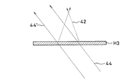
すなわち、図4に示すように、第3ホログラムH3記録時の再生照明光34の入射角と同じ角度の照明光44で第3ホログラムH3を照明すると、その照明光44中の再生照明光34の波長と同じ波長の成分は収束光32と同じ収束光42として透過側に回折される。そして、照明光44中のそれ以外の波長の成分は第3ホログラムH3に記録された干渉縞の回折格子の波長分散作用により収束光42の収束点の左右に分光されて収束する。しかも、第3ホログラムH3には、マイクロレンズアレーOの微小レンズLと同じ間隔でこのような作用をする要素ホログラムがアレー状に記録されているので、この第3ホログラムH3は液晶表示装置(LCD)等の画像表示装置用のホログラムカラーフィルターとして使用可能なものとなる。なお、図4中、符号44’は照明光44が第3ホログラムH3で回折されないで透過する0次光成分である。
【0035】
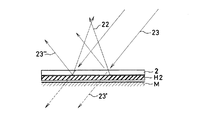
ところで、上記の図2の配置で第2ホログラムH2を記録する際、再生照明光23とは別にその入射側と反対側から参照光24を入射させるものとしたが、この参照光24の代わりに、ホログラム感光材料2と第1ホログラムH1を直通した再生照明光23の0次光をその代わりに用いるようにしてもよい。その場合の配置を図5に示す。図2に代わるこの配置では、第1ホログラムH1のホログラム感光材料2とは反対側に平面ミラーMを配置する。このように第1ホログラムH1の再生照明光23透過側に平面ミラーMを配置すると、ホログラム感光材料2と第1ホログラムH1を直通した透過光23’は平面ミラーMで反射されて反射光23”となり、参照光24の透過光24’と同様の光となり、ホログラム感光材料2中に前記の干渉縞▲2▼と干渉縞▲3▼を形成することになる。なお、前記したように、透過光24’を形成する参照光24は、作製しようとするホログラムカラーフィルターへの照明光の入射角と同じ角度に選ぶ必要があるので、図5の配置をとる場合は、反射光23”がこのような条件を満足するように平面ミラーMの角度を調整するか、再生照明光23の入射角、すなわち、図1の配置の参照光13の入射角がホログラムカラーフィルターへの照明光の入射角と同じになるように設定する。後者の場合は、平面ミラーMは第1ホログラムH1に近接あるいは密着して平行に配置する。
【0036】
このようにして作製された第3ホログラムH3は、上記のように収束要素ホログラムアレーからなるホログラムレンズアレーであり、上記のようにホログラムカラーフィルターとして使用することが可能である。特に、直視型LCD用のホログラムカラーフィルターを作製する場合、大面積のものである必要があるが、そのホログラム原版としてCGH等を使用することは、その描画寸法の制限から考えて困難である。また、作製されたCGHを多面付けで配列することも考えられるが、つなぎ目を見えなくすることは難しい。上記の本発明の方法においては、大面積のものが比較的容易に入手できるレンチキラーレンズ、マイクロレンズアレーを原版に使用可能なため、このような制約がなくなり、容易に直視LCD用のホログラムカラーフィルターを作製することが可能となる。
【0037】
ところで、以上の実施例においては、反射型の第1ホログラムH1は、図1に示すように、マイクロレンズアレーOとホログラム感光材料1を近接あるいは密着して配置することにより記録している。この場合は、実際上、マイクロレンズアレーOの曲面のレンズ面側にホログラム感光材料1が配置されるため、マイクロレンズアレーOとホログラム感光材料1の間に空気間隔が介在せざるを得ず、空気との界面で不要反射光が生じ、記録されるホログラムH1中に不要干渉縞が記録され、最終製品H3の特性が悪化する。加えて、特願平7−249115号中に記載されているように、マイクロレンズアレーOと同じ焦点距離のホログラムアレーの作製が困難であると同時に、ホログラムが記録されない領域が生じてしまう恐れがある。
【0038】
そこで、図1の配置の代わりに、特願平7−249115号の複製方法と同様にして、図6に示すように、マイクロレンズアレーOのレンズ面と反対側の平面とフォトポリマーのような体積ホログラム感光材料1との間にスペーサ14を介してその間の間隔をマイクロレンズアレーOを構成する微小正レンズあるいは微小正シリンドリカルレンズLの焦点距離fの略2倍に設定して、マイクロレンズアレーOのレンズ面側から平行照明光11で照明すると、透過側に各微小レンズLから収束光が出てその焦点面に一旦収束し、その後発散光となり、マイクロレンズアレーOから焦点距離fの略2倍の位置で各微小レンズL位置でのビーム径と同じ径になり、その位置にあるホログラム感光材料1に物体光12として入射する。それと当時に、所定の斜め方向から参照光13をホログラム感光材料1の反対側の面(下面)から入射させ、物体光12と参照光13をホログラム感光材料1中で干渉させて第1ホログラムH1を記録する。ただし、このようにして記録された第1ホログラムH1に、その記録時の参照光13と同じ方向から再生照明光23を入射させると、第1ホログラムH1からは記録時の物体光12と同様の発散光が回折光として生じるので、図2の第2ホログラムH2記録時には、再生照明光23は第1ホログラムH1記録時の参照光13と反対の方向から入射させるようにする。このような再生照明光23を入射させると、第1ホログラムH1から回折される回折光は、第1ホログラムH1記録時の物体光12と反対方向に進む収束光22となる。以下、図2〜図5は同様にして、同様の第3ホログラムH3が作製される。
【0039】
なお、この図6の配置の場合は、図1の配置と異なり、照明光11をマイクロレンズアレーOの曲面のレンズ面側から入射させているため(図1の配置では、マイクロレンズアレーOの曲面のレンズ面と反対側から入射させている。)、マイクロレンズアレーOと体積ホログラム感光材料1の間を、屈折率がマイクロレンズアレーO及び体積ホログラム感光材料1に略等しい媒質であるスペーサ14で埋めることができ、その間での界面反射を減らして効率良くかつ不要干渉縞を減らして第1ホログラムH1を記録できる。しかし、図6の配置において、物体光12がホログラム感光材料1を透過し、その裏面で界面反射されて再びホログラム感光材料1の感光層に戻って不要干渉縞を記録してしまう恐れがある。同様に、参照光13がホログラム感光材料1を透過し、マイクロレンズアレーOの界面等で反射されて再びホログラム感光材料1の感光層に戻って不要干渉縞を記録してしまう恐れがある。このような界面反射による不要干渉縞の記録を防止するために、ホログラム感光材料1の裏面側に光吸収層15を配置し、また、スペーサ14を光吸収性とするか、その一部に光吸収層を設けるようにすると、上記のような往復動作をする界面反射光を大幅に低減させることができるので好ましい。そのためのこれら光吸収層の透過率については、種々の実験結果から50%以下であることが望ましい。なお、ホログラム感光材料1の裏面側に配置する光吸収層15の空気との界面(ホログラム感光材料1とは反対の側の表面)に、反射防止膜を施すと、その面での界面反射がなくなるのでさらに好ましい。
【0040】
図1の反射型の第1ホログラムH1の記録配置に代わるもう1つの方法は、図7(a)、(b)に示すようなマイクロレンズアレーOの代わりにマイクロミラーアレーB、B’を用いる方法が考えられる。図7(a)のマイクロミラーアレーBは微小凹面鏡あるいは微小円筒凹面鏡Cの規則正しいアレーからなるもので、そのマイクロミラーアレーBの上に、ホログラム感光材料1の基板と屈折率が略等しい媒質16を介してフォトポリマーのような体積ホログラム感光材料1を近接あるいは密着して平行に配置し、ホログラム感光材料1側から垂直に照明光13’を入射させると、その照明光13’はホログラム感光材料1を透過し、マイクロミラーアレーBに入射して各微小凹面鏡あるいは微小円筒凹面鏡Cで反射されて収束光となる。この収束光が物体光12としてホログラム感光材料1の下面から入射し、その物体光12と入射光13’とがホログラム感光材料1中で干渉して第1ホログラムH1が記録される。
【0041】
また、図7(b)のマイクロミラーアレーB’は微小凸面鏡あるいは微小円筒凸面鏡C’の規則正しいアレーからなるもので、そのマイクロミラーアレーB’の上に、ホログラム感光材料1の基板と屈折率が略等しい媒質16を介してフォトポリマーのような体積ホログラム感光材料1を近接あるいは密着して平行に配置し、ホログラム感光材料1側から垂直に照明光13’を入射させると、その照明光13’はホログラム感光材料1を透過し、マイクロミラーアレーB’に入射して各微小凸面鏡あるいは微小円筒凸面鏡C’で反射されて各々の焦点Fから発散する発散光となる。この発散光が物体光12としてホログラム感光材料1の下面から入射し、その物体光12と入射光13’とがホログラム感光材料1中で干渉して第1ホログラムH1が記録される。ただし、このようにして記録された第1ホログラムH1に、その記録時の照明光13’と同じ方向から再生照明光23を入射させると、第1ホログラムH1からは記録時の物体光12と同様の発散光が回折光として生じるので、図2の第2ホログラムH2記録時には、再生照明光23は第1ホログラムH1記録時の照明光13’と反対の方向から入射させるようにする。このような再生照明光23を入射させると、第1ホログラムH1から回折される回折光は、第1ホログラムH1記録時の物体光12と反対方向に進む収束光22となる。
【0042】
この図7の場合も、ホログラム感光材料1の入射側に光吸収層15を配置すると、物体光12がホログラム感光材料1を透過し、その裏面で界面反射されて再びホログラム感光材料1の感光層に戻って不要干渉縞を記録してしまうのを防止することができるので好ましい。この光吸収層15透過率については、種々の実験結果から50%以下であることが望ましい。なお、この場合も、光吸収層15の空気との界面(ホログラム感光材料1とは反対の側の表面)に、反射防止膜を施すと、その面での界面反射がなくなるのでさらに好ましい。
【0043】
図7のようなマイクロミラーアレーB、B’を用いる配置では、第1ホログラムH1記録時に使用するレーザ光を2光束から1光束に減らすことができ、撮影時にレーザ及び撮影光学系の可干渉性の変動による不安定さを大幅に低減することが可能となる。なお、マイクロミラーアレーB’としては、図1のマイクロレンズアレーOのようなマイクロレンズアレーのレンズ面にアルミニウム等の反射コートしたものを用いることができる。
【0044】
さて、以上の本発明の特徴は、マイクロレンズアレー等から1回目の作製で透過型ホログラムを作製することは困難なため、1回目(図1、図6、図7)の作製においては、容易に作製可能な反射型ホログラムを作製し、この反射型ホログラムからの回折光と参照光とを別のホログラム感光材料中に記録することで(図2)、元のマイクロレンズアレー等の持つ特性を透過型ホログラムに記録することである。
【0045】
なお、以上のようにして作製した第3ホログラムH3を透過型ホログラム原版として、それから通常の透過型ホログラムの複製法に従ってホログラムカラーフィルターを量産するようにしてもよい。あるいは、第2ホログラムH2を透過型ホログラム原版として、それから図3の配置の透過型ホログラムの複製法に従ってホログラムカラーフィルターを量産するようにしてもよい。
【0046】
さて、本発明の透過型ホログラムの作製方法は、上記のようなホログラムカラーフィルターの作製方法に限らず、通常の被写体を再生する透過型ホログラムや、透過型スクリーン等に用いる透過型ホログラム散乱板、レンズアレーとフレネルレンズを重ね合わせてなる透過型スクリーンの作製方法に適用することもできる。これらの場合、図1、図7の配置が若干異なるのみで、図2〜図5は同様に適用できる。図8(a)に、反射散乱型の被写体O’から第1ホログラムH1をデニシューク型の反射型ホログラムとして記録する場合の配置を示す。この場合は、被写体O’の前方に比較的近接して体積ホログラム感光材料1を配置し、ホログラム感光材料1側の所定の斜め方向から照明光(参照光)13を入射させると、その光はホログラム感光材料1を透過して反対側の被写体O’を照明し、その表面から散乱光12’が出てホログラム感光材料1に裏面側から入射し、その散乱光12’と照明光13がホログラム感光材料1中で干渉して第1ホログラムH1(図2)が反射型ホログラムとして記録される。この場合の、図2以降の工程はホログラムカラーフィルターの場合と同様である。なお、反射散乱型の被写体O’として反射型回折格子、反射型散乱板を用いて透過型回折格子、透過型散乱板を作製することもできる。
【0047】
上記のような配置で第1ホログラムH1を撮影すると、被写体O’をホログラム感光材料1に近接して配置できるため、記録に利用する散乱光12’の散乱角が広くなる。そのため、最終製品の第3ホログラムH3から出る散乱光42(図4)の散乱角も広くなるので、視域の広い透過型ホログラムとなり、グラフィックアート等に好適となる。
【0048】
また、図8(b)に、すりガラス、オパールガラス等の透過型散乱板O”から第1ホログラムH1を反射型ホログラムとして記録する場合の配置を示す。この場合は、透過型散乱板O”の前方に比較的近接して体積ホログラム感光材料1を配置し、透過型散乱板O”の裏面から照明光11’で照明すると共に、ホログラム感光材料1の反対側から側の所定の斜め方向から照明光(参照光)13を入射させる。裏面から照明光11’で照明されると透過型散乱板O”の前方に散乱光12”が出てホログラム感光材料1に裏面側から入射し、その散乱光12”と照明光13がホログラム感光材料1中で干渉して第1ホログラムH1(図2)が反射型ホログラムとして記録される。この場合も、図2以降の工程はホログラムカラーフィルターの場合と同様である。
【0049】
また、上記のような配置で第1ホログラムH1を撮影すると、透過型散乱板O”をホログラム感光材料1に近接して配置できるため、記録に利用する散乱光12”の散乱角が広くなる。そのため、最終製品の第3ホログラムH3から出る散乱光42(図4)の散乱角も広くなるので、視域の広い透過型ホログラム散乱板となり、従来の散乱光と参照光をホログラム感光材料の同じ側から入射させて撮影したものと比較してより広い視域がとれより優れたものとなる。
【0050】
なお、図8(b)の場合も、図8(a)と同様にデニシューク型の反射型ホログラムとして記録するようにしてもよい。
【0051】
以上、本発明の透過型ホログラムの作製方法を実施例の基づいて説明してきたが、本発明はこれら実施例に限定されず種々の変形が可能である。
【0052】
【発明の効果】
以上の説明から明らかなように、本発明の透過型ホログラムの作製方法によると、最終的に再生したい波面をまず第1ホログラムとして視域の広い反射型ホログラムとして撮影し、次いでこの第1ホログラムを用いて反射型と透過型の混合した第2ホログラムを撮影し、第3段階として第3ホログラム感光材料中にその第2ホログラム中に記録された再生したい波面のみを再生する透過型ホログラムのみを分離して複製するので、視域が広くまた大面積の透過型ホログラムを簡単に作製することができる。本発明の方法は、例えば、CGHを用いないで大面積のホログラムカラーフィルターを作製するのに適用できる。
【図面の簡単な説明】
【図1】本発明に基づいてホログラムカラーフィルターをマイクロレンズアレーを用いて作製する第1の工程を説明するための図である。
【図2】図1に続く第2の工程を説明するための図である。
【図3】図2に続く第3の工程を説明するための図である。
【図4】最終的に作製されたホログラムカラーフィルターを説明するための図である。
【図5】図2の工程に代わる方法を説明するための図である。
【図6】図1の第1の工程の変形例を説明するための図である。
【図7】図1の第1の工程の別の変形例を説明するための図である。
【図8】通常の被写体を再生する透過型ホログラムの作製と透過型ホログラム散乱板の作製の場合の図1の工程に代わる方法を説明するための図である。
【符号の説明】
O…マイクロレンズアレー
O’…反射散乱型被写体
O”…透過型散乱板
L…微小レンズ
M…平面ミラー
B、B’…マイクロミラーアレー
C…微小凹面鏡あるいは微小円筒凹面鏡
C’…微小凸面鏡あるいは微小円筒凸面鏡
F…焦点
H1…第1ホログラム
H2…第2ホログラム
H3…第3ホログラム
1…体積ホログラム感光材料
2…体積ホログラム感光材料
3…ホログラム感光材料
11…平行照明光
11’…照明光
12…物体光(収束光)
12’…散乱光
12”…散乱光
13…参照光(照明光)
13’…照明光
14…スペーサ
15…光吸収層
16…透明媒質
22…収束光(回折光)
23…再生照明光
23’…透過光
23”…反射光
24…参照光
24’…透過光
32…収束光(回折光)
33’…回折光
34…再生照明光
34’…0次光(透過光)
42…収束光(回折光)、散乱光
44…照明光
44’…0次光[0001]
BACKGROUND OF THE INVENTION
The present invention relates to a method for producing a transmission hologram, and more particularly to a novel method for producing a transmission hologram capable of producing various types of transmission holograms with a simple configuration and a wide viewing area and a large area.
[0002]
[Prior art]
The present applicant has proposed a hologram color filter as a kind of transmission hologram in JP-A-6-308332. This hologram color filter is an array of a kind of condensing optical element that condenses obliquely incident parallel light beams in the front direction, and as one method for its production, convergence from a condensing lens from the same side of the hologram photosensitive material. It is manufactured by making light and reference light from an oblique direction enter and interfere in the hologram photosensitive material. In addition, as another method, a computer generated hologram (CGH) is manufactured, and the hologram is replicated using the computer generated hologram as a master.
[0003]
In addition, as a method for replicating the transmission type condensing element hologram array as described above, the applicant of the present application disclosed in Japanese Patent Application No. 7-249115 the distance between the original plate and the hologram photosensitive material as the focal length of the element hologram. A method of replicating a hologram having characteristics similar to those of the original plate is set.
[0004]
In addition, a transmission hologram scattering plate such as a transmission hologram screen or a transmission hologram of a subject used for graphic art or the like applies illumination light to a scattering plate or a three-dimensional object as a subject from the back surface or the front surface. Photographing is performed by causing scattered light and reference light emitted from an object or the like to enter from the same side of the hologram photosensitive material and cause interference in the hologram photosensitive material.
[0005]
[Problems to be solved by the invention]
In this way, in order to directly photograph a transmission hologram, object light and reference light emitted from a transparent object (condensing lens, scattering plate) or a three-dimensional object corresponding to a subject are incident from the same side of the hologram photosensitive material. Since the subject cannot be photographed close to the hologram photosensitive material, the viewing area of the completed transmission hologram scattering plate, transmission art such as graphic art is limited, and the range that the observer can observe is limited. It will be narrow.
[0006]
In the case of a hologram color filter, it is very time-consuming to manufacture because a minute element hologram has to be recorded in an array while moving the condenser lens in a step-and-repeat manner. Therefore, in practice, a CGH original plate is produced and then produced by a hologram replication method. However, since it is difficult to produce a large CGH original plate, it is not easy to produce a large hologram color filter.
[0007]
The present invention has been made in view of such problems of the prior art, and an object of the present invention is to provide a method capable of producing various types of transmission holograms with a simple configuration and a wide viewing area and a large area. That is.
[0008]
[Means for Solving the Problems]
The method for producing a transmission hologram of the present invention that achieves the above object is a method for producing a transmission hologram that diffracts a reproduction wavefront in the direction opposite to the incident direction when reproduction illumination light is incident.
A reflection-type first hologram is photographed by causing an object wavefront from a subject and a first reference wavefront to enter and interfere with each other from opposite sides of the first hologram photosensitive material,
The second hologram photosensitive material is disposed on the first reference wavefront incident side at the time of recording the first hologram, the first reproduction illumination light is incident on the first hologram through the hologram photosensitive material, and the reproduction wavefront is diffracted. A second reference wavefront having the same wavelength is incident from an opposite side to the incident side of the first reproduction illumination light at an angle that does not satisfy the Bragg diffraction condition of the interference fringes recorded in the first hologram, and at least the reproduction wavefront and the first wavefront The second hologram is photographed by interfering with the first hologram transmitted light of the two reference wavefronts,
A third hologram photosensitive material is disposed on the first reproduction illumination light incident side at the time of recording the second hologram, and the second reproduction illumination light corresponding to the first hologram transmitted light at the second reference wavefront at the time of the second hologram recording is provided as the first. The two holograms are incident from the opposite side of the third hologram photosensitive material to diffract the reproduction wavefront, and the reproduction wavefront interferes with the second hologram transmission light of the second reproduction illumination light to enter the third hologram photosensitive material. It is a method characterized by recording.
[0009]
In this case, the second reference wavefront at the time of photographing the second hologram is the first reproduction illumination light transmitted through the second hologram photosensitive material and the first hologram, and is disposed on the opposite side of the first hologram from the second hologram photosensitive material. It is also possible to have a reflected wavefront reflected by the reflecting means.
[0010]
Further, the subject may be a lens array, and the object wavefront may be a convergent wavefront group converged by each lens of the lens array.
[0011]
In that case, the second reference wavefront at the time of recording the second hologram is made incident on the second hologram photosensitive material at a predetermined oblique incident angle, and the transmission hologram recorded in the third hologram photosensitive material becomes the hologram color filter. Can be.
[0012]
Further, the first hologram may be photographed as a Denniske-type reflection hologram of a reflection / scattering type subject.
[0013]
Further, the first hologram may be photographed as a reflection hologram of a scattering plate.
[0014]
Further, the first hologram may be photographed as a reflection hologram of a transmissive body formed by superimposing a lens array and a Fresnel lens.
[0015]
Further, a transmission hologram recorded in the third hologram photosensitive material may be used as an original for hologram replication.
[0016]
Alternatively, the second hologram can be replicated on the third hologram photosensitive material as an original for hologram replication.
[0017]
Another method for producing a transmission hologram according to the present invention is a method for producing a transmission hologram that diffracts a reproduction wavefront in the direction opposite to the incident direction when reproduction illumination light is incident.
The reflection type first hologram is photographed on the first hologram photosensitive material using the wavefront group converged or diverged by each lens of the lens array as object light,
The second hologram photosensitive material is disposed on the reproduction illumination light incident side of the first hologram and irradiated with the reproduction illumination light, and at the same time, recorded on the first hologram on the side opposite to the reproduction illumination light incidence side of the first hologram. Reproducing illumination light and coherent reference light are incident at an angle that does not satisfy the Bragg diffraction condition of the interference fringes, and the reproducing illumination light, the reproduced light from the first hologram, and the first hologram transmitted light of the reference light interfere with each other. To shoot the second hologram,
The third hologram photosensitive material is arranged on the side of the reproduction illumination light incident side at the time of recording the second hologram, and the reproduction illumination light corresponding to the reference light at the time of recording the second hologram is opposite to the third hologram photosensitive material of the second hologram. A transmission hologram that reproduces the convergent wavefront group in the third hologram photosensitive material by causing the reproduction light from the second hologram and the second hologram transmission light of the reproduction illumination light to interfere with each other.
Further, when photographing the first hologram, illumination light is incident from the lens surface side of the curved surface of the lens array in order to generate a wavefront group of object light from the lens array, and the lens array and the first hologram photosensitive The material is filled with a medium having a refractive index substantially equal to that of the lens array and the first hologram photosensitive material.
[0018]
In this case, the first hologram may be photographed by arranging the first hologram photosensitive material at a position that is approximately twice the focal length condensed by each lens of the lens array.
[0019]
In addition, it is desirable to arrange a light absorption layer between the lens array and the first hologram photosensitive material when photographing the first hologram.
[0020]
In that case, the transmittance of the light absorption layer is preferably 50% or less.
[0021]
Further, it is desirable to dispose a light absorption layer on the side opposite to the lens array of the first hologram photosensitive material when photographing the first hologram.
[0022]
Also in that case, the transmittance of the light absorption layer is desirably 50% or less.
[0023]
According to still another aspect of the present invention, there is provided a transmission hologram manufacturing method for diffracting a reproduction wavefront in a direction opposite to the incident direction when reproducing illumination light is incident.
A first hologram photosensitive material is disposed in front of a curved mirror array, illumination light is incident on the curved mirror array through the first hologram photosensitive material, and the wavefront converges or diverges reflected by each mirror of the curved mirror array. The first hologram of the reflection type is photographed by causing the illumination light to interfere with the group,
The second hologram photosensitive material is disposed on the reproduction illumination light incident side of the first hologram and irradiated with the reproduction illumination light, and at the same time, recorded on the first hologram on the side opposite to the reproduction illumination light incidence side of the first hologram. Reproducing illumination light and coherent reference light are incident at an angle that does not satisfy the Bragg diffraction condition of the interference fringes, and the reproducing illumination light, the reproduced light from the first hologram, and the first hologram transmitted light of the reference light interfere with each other. To shoot the second hologram,
The third hologram photosensitive material is arranged on the side of the reproduction illumination light incident side at the time of recording the second hologram, and the reproduction illumination light corresponding to the reference light at the time of recording the second hologram is opposite to the third hologram photosensitive material of the second hologram. A transmission hologram that reproduces the converged wavefront group in the third hologram photosensitive material by causing the reproduction light from the second hologram to interfere with the second hologram transmission light of the reproduction illumination light. It is a method.
[0024]
In this case, it is desirable to fill the space between the curved mirror array and the first hologram photosensitive material with a medium having a refractive index substantially equal to that of the first hologram photosensitive material at the time of photographing the first hologram.
[0025]
Further, it is desirable to arrange a light absorption layer on the opposite side of the first hologram photosensitive material from the curved mirror array at the time of photographing the first hologram.
[0026]
In that case, the transmittance of the light absorption layer is preferably 50% or less.
[0027]
A reflective diffraction grating or a reflective scattering plate can be used instead of the curved mirror array.
[0028]
In the present invention, a wavefront to be finally reproduced is first photographed as a reflection hologram having a wide viewing zone as a first hologram, and then a second hologram mixed with a reflection type and a transmission type is photographed using the first hologram. In the third stage, only the transmission hologram that reproduces only the wavefront to be reproduced recorded in the second hologram is separated and duplicated in the third hologram photosensitive material, so that the transmission type having a wide viewing area and a large area is reproduced. A hologram can be easily produced. The method of the present invention can be applied to, for example, producing a large-area hologram color filter without using CGH.
[0029]
DETAILED DESCRIPTION OF THE INVENTION
Hereinafter, a method for producing a transmission hologram of the present invention will be described based on examples.
[0030]
1 to 4 are diagrams for explaining a process of manufacturing a hologram color filter using a microlens array.
[0031]
First, as shown in FIG. 1, a microlens array O composed of a regular array of minute positive lenses or minute positive cylindrical lenses L and a volume hologram
[0032]
Next, using this first hologram H1, a second hologram H2 is produced in the arrangement of FIG. That is, another volume hologram
[0033]
Using the second hologram H2 recorded in this manner, as shown in FIG. 3, another hologram
[0034]
That is, as shown in FIG. 4, when the third hologram H3 is illuminated with
[0035]
By the way, when recording the second hologram H2 with the arrangement of FIG. 2 described above, the
[0036]
The third hologram H3 produced in this way is a hologram lens array composed of a converging element hologram array as described above, and can be used as a hologram color filter as described above. In particular, when producing a hologram color filter for a direct-view LCD, it is necessary to have a large area, but it is difficult to use CGH or the like as the hologram master because of the limitation of the drawing size. Although it is conceivable to arrange the produced CGHs in a multi-faceted manner, it is difficult to make the joints invisible. In the above-described method of the present invention, a lenticular killer lens and a microlens array, which can be obtained with a relatively large area, can be used as an original plate. A filter can be produced.
[0037]
In the above embodiment, the reflection type first hologram H1 is recorded by arranging the microlens array O and the hologram
[0038]
Therefore, instead of the arrangement of FIG. 1, as shown in FIG. 6, a plane opposite to the lens surface of the microlens array O and a photopolymer like the one shown in FIG. The space between the
[0039]
In the arrangement of FIG. 6, unlike the arrangement of FIG. 1, the
[0040]
Another method for replacing the recording arrangement of the reflective first hologram H1 of FIG. 1 uses micromirror arrays B and B ′ instead of the microlens array O as shown in FIGS. 7A and 7B. A method is conceivable. The micromirror array B in FIG. 7A is composed of a regular array of micro concave mirrors or micro cylindrical concave mirrors C, and a medium 16 having a refractive index substantially equal to the substrate of the hologram
[0041]
Further, the micromirror array B ′ in FIG. 7B is composed of a regular array of minute convex mirrors or minute cylindrical convex mirrors C ′. On the micromirror array B ′, the substrate and the refractive index of the hologram
[0042]
In the case of FIG. 7 as well, when the
[0043]
In the arrangement using the micromirror arrays B and B ′ as shown in FIG. 7, the laser beam used at the time of recording the first hologram H1 can be reduced from two beams to one beam. It is possible to significantly reduce instability due to fluctuations in As the micromirror array B ′, a lens surface of a microlens array such as the microlens array O of FIG.
[0044]
The feature of the present invention described above is that it is difficult to produce a transmission hologram by the first production from a microlens array or the like, so that the first production (FIGS. 1, 6, and 7) is easy. By fabricating a reflection hologram that can be fabricated in a simple manner and recording the diffracted light and reference light from this reflection hologram in different hologram photosensitive materials (FIG. 2), the characteristics of the original microlens array and the like can be obtained. It is to record on a transmission hologram.
[0045]
The third hologram H3 produced as described above may be used as a transmission hologram master, and then a hologram color filter may be mass-produced according to a normal transmission hologram replication method. Alternatively, the second hologram H2 may be used as a transmission hologram master, and then a hologram color filter may be mass-produced in accordance with the transmission hologram replication method shown in FIG.
[0046]
The method for producing a transmission hologram of the present invention is not limited to the method for producing a hologram color filter as described above, but a transmission hologram for reproducing a normal subject, a transmission hologram scattering plate used for a transmission screen, etc. The present invention can also be applied to a method for manufacturing a transmission screen in which a lens array and a Fresnel lens are overlapped. In these cases, only the arrangement of FIGS. 1 and 7 is slightly different, and FIGS. 2 to 5 can be similarly applied. FIG. 8A shows an arrangement in the case where the first hologram H1 is recorded as a Denniske-type reflection hologram from the reflection / scattering type object O ′. In this case, when the volume hologram
[0047]
When the first hologram H1 is photographed in the above-described arrangement, the subject O ′ can be arranged close to the hologram
[0048]
FIG. 8B shows an arrangement in the case where the first hologram H1 is recorded as a reflection hologram from a transmission type scattering plate O ″ such as ground glass or opal glass. In this case, the transmission type scattering plate O ″ The volume hologram
[0049]
Further, when the first hologram H1 is photographed in the above arrangement, the transmission type scattering plate O ″ can be arranged close to the hologram
[0050]
In the case of FIG. 8B as well, recording may be performed as a Denniske-type reflection hologram as in FIG. 8A.
[0051]
As mentioned above, although the manufacturing method of the transmission hologram of this invention has been demonstrated based on the Example, this invention is not limited to these Examples, A various deformation | transformation is possible.
[0052]
【The invention's effect】
As is clear from the above description, according to the method for producing a transmission hologram of the present invention, the wavefront to be finally reproduced is first photographed as a reflection hologram having a wide viewing zone as the first hologram, and then this first hologram is photographed. Use this to shoot a second hologram mixed with reflection type and transmission type, and in the third stage, separate only the transmission type hologram that reproduces only the wavefront to be reproduced recorded in the second hologram in the third hologram photosensitive material. Therefore, a transmission hologram having a wide viewing area and a large area can be easily produced. The method of the present invention can be applied to, for example, producing a large-area hologram color filter without using CGH.
[Brief description of the drawings]
FIG. 1 is a view for explaining a first step of producing a hologram color filter using a microlens array according to the present invention.
FIG. 2 is a diagram for explaining a second step following FIG. 1;
FIG. 3 is a diagram for explaining a third step following FIG. 2;
FIG. 4 is a diagram for explaining a hologram color filter finally produced.
FIG. 5 is a diagram for explaining an alternative method to the process of FIG. 2;
6 is a diagram for explaining a modification of the first step in FIG. 1; FIG.
7 is a diagram for explaining another modified example of the first step in FIG. 1; FIG.
FIG. 8 is a diagram for explaining an alternative method to the process of FIG. 1 in the case of producing a transmission hologram for reproducing a normal subject and producing a transmission hologram scattering plate.
[Explanation of symbols]
O ... Microlens array
O '... Reflection scattering type subject
O "... Transmission type scattering plate
L ... micro lens
M ... Flat mirror
B, B '... Micromirror array
C: Micro concave mirror or micro cylindrical concave mirror
C ': Micro convex mirror or micro cylindrical convex mirror
F ... Focus
H1 ... 1st hologram
H2 ... 2nd hologram
H3 ... Third hologram
1 ... Volume hologram photosensitive material
2 ... Volume hologram photosensitive material
3 ... Hologram photosensitive material
11 ... Parallel illumination light
11 '... Illumination light
12 ... Object light (convergent light)
12 '... scattered light
12 "... scattered light
13. Reference light (illumination light)
13 '... Illumination light
14 ... Spacer
15 ... light absorption layer
16 ... Transparent medium
22 ... Convergent light (diffracted light)
23 ... Reproduction illumination light
23 '... transmitted light
23 "... Reflected light
24 ... Reference light
24 '... transmitted light
32 ... Convergent light (diffracted light)
33 '... Diffracted light
34 ... Reproduction illumination light
34 '... 0th order light (transmitted light)
42 ... convergent light (diffracted light), scattered light
44 ... Illumination light
44 '... 0th order light
Claims (20)
被写体からの物体波面と第1参照波面とを第1ホログラム感光材料の相互に反対の側から入射させて干渉させることにより反射型の第1ホログラムを撮影し、 第1ホログラムの記録時の第1参照波面入射側に第2ホログラム感光材料を配置してそのホログラム感光材料を通して第1再生照明光を第1ホログラムに入射させて再生波面を回折させ、かつ、同時に第1再生照明光の入射側とは反対側から同じ波長の第2参照波面を第1ホログラムに記録された干渉縞のブラッグの回折条件を満足しない角度で入射させて、少なくとも前記再生波面と第2参照波面の第1ホログラム透過光とを干渉させることにより第2ホログラムを撮影し、
第2ホログラムの記録時の第1再生照明光入射側に第3ホログラム感光材料を配置し、第2ホログラム記録時の第2参照波面の第1ホログラム透過光に相当する第2再生照明光を第2ホログラムの第3ホログラム感光材料とは反対側から入射させて再生波面を回折させ、その再生波面と第2再生照明光の第2ホログラム透過光とを干渉させることにより第3ホログラム感光材料中に記録したことを特徴とする透過型ホログラムの作製方法。In the method for producing a transmission hologram that diffracts the reproduction wavefront in the direction opposite to the incident direction when the reproduction illumination light is incident,
The reflection-type first hologram is photographed by causing the object wavefront from the subject and the first reference wavefront to enter and interfere with each other from the opposite sides of the first hologram photosensitive material, and the first hologram recording time is recorded. The second hologram photosensitive material is disposed on the reference wavefront incident side, the first reproduction illumination light is incident on the first hologram through the hologram photosensitive material to diffract the reproduction wavefront, and at the same time, the first reproduction illumination light incident side The second reference wavefront having the same wavelength is incident from the opposite side at an angle that does not satisfy the Bragg diffraction conditions of the interference fringes recorded on the first hologram, and the first hologram transmitted light of at least the reproduction wavefront and the second reference wavefront The second hologram is photographed by interfering with
A third hologram photosensitive material is disposed on the first reproduction illumination light incident side at the time of recording the second hologram, and the second reproduction illumination light corresponding to the first hologram transmitted light at the second reference wavefront at the time of the second hologram recording is provided as the first. The two holograms are incident from the opposite side of the third hologram photosensitive material to diffract the reproduction wavefront, and the reproduction wavefront interferes with the second hologram transmission light of the second reproduction illumination light to enter the third hologram photosensitive material. A method for producing a transmission hologram, wherein the transmission hologram is recorded.
レンズアレーの各レンズで収束されるか一旦収束された後に発散された波面群を物体光として第1ホログラム感光材料に反射型の第1ホログラムを撮影し、
この第1ホログラムの再生照明光入射側に第2ホログラム感光材料を配置して再生照明光を照射すると同時に、第1ホログラムの再生照明光入射側と反対側に、この第1ホログラムに記録された干渉縞のブラッグの回折条件を満足しない角度で再生照明光と可干渉な参照光を入射させ、前記再生照明光と第1ホログラムからの再生光と前記参照光の第1ホログラム透過光とを干渉させることにより第2ホログラムを撮影し、
第2ホログラムの記録時の再生照明光入射側に第3ホログラム感光材料を配置し、第2ホログラム記録時の参照光に相当する再生照明光を第2ホログラムの第3ホログラム感光材料とは反対側から入射させ、第2ホログラムからの再生光とと再生照明光の第2ホログラム透過光とを干渉させることにより第3ホログラム感光材料中に収束波面群を再生する透過型ホログラムを撮影し、
かつ、前記第1ホログラムの撮影時に、レンズアレーから物体光の波面群を発生させるために前記レンズアレーの曲面のレンズ面側から照明光を入射させ、また、前記レンズアレーと前記第1ホログラム感光材料の間を屈折率が前記レンズアレーと前記第1ホログラム感光材料に略等しい媒質で埋めるようにしたことを特徴とする透過型ホログラムの作製方法。In the method for producing a transmission hologram that diffracts the reproduction wavefront in the direction opposite to the incident direction when the reproduction illumination light is incident,
The reflection type first hologram is photographed on the first hologram photosensitive material using the wavefront group converged by each lens of the lens array or once converged after being converged as object light,
The second hologram photosensitive material is disposed on the reproduction illumination light incident side of the first hologram and irradiated with the reproduction illumination light, and at the same time, recorded on the first hologram on the side opposite to the reproduction illumination light incidence side of the first hologram. Reproducing illumination light and coherent reference light are incident at an angle that does not satisfy the Bragg diffraction condition of the interference fringes, and the reproducing illumination light, the reproduced light from the first hologram, and the first hologram transmitted light of the reference light interfere with each other. To shoot the second hologram,
The third hologram photosensitive material is arranged on the side of the reproduction illumination light incident side at the time of recording the second hologram, and the reproduction illumination light corresponding to the reference light at the time of recording the second hologram is opposite to the third hologram photosensitive material of the second hologram. A transmission hologram that reproduces the convergent wavefront group in the third hologram photosensitive material by causing the reproduction light from the second hologram and the second hologram transmission light of the reproduction illumination light to interfere with each other.
Further, when photographing the first hologram, illumination light is incident from the lens surface side of the curved surface of the lens array in order to generate a wavefront group of object light from the lens array, and the lens array and the first hologram photosensitive A method for producing a transmission hologram, wherein a material is filled with a medium having a refractive index substantially equal to that of the lens array and the first hologram photosensitive material.
曲面ミラーアレーの前方に第1ホログラム感光材料を配置し、前記第1ホログラム感光材料を通して前記曲面ミラーアレーに照明光を入射させて、前記曲面ミラーアレーの各ミラーで反射された収束あるいは発散する波面群と前記照明光を干渉させて反射型の第1ホログラムを撮影し、
この第1ホログラムの再生照明光入射側に第2ホログラム感光材料を配置して再生照明光を照射すると同時に、第1ホログラムの再生照明光入射側と反対側に、この第1ホログラムに記録された干渉縞のブラッグの回折条件を満足しない角度で再生照明光と可干渉な参照光を入射させ、前記再生照明光と第1ホログラムからの再生光と前記参照光の第1ホログラム透過光とを干渉させることにより第2ホログラムを撮影し、
第2ホログラムの記録時の再生照明光入射側に第3ホログラム感光材料を配置し、第2ホログラム記録時の参照光に相当する再生照明光を第2ホログラムの第3ホログラム感光材料とは反対側から入射させ、第2ホログラムからの再生光とと再生照明光の第2ホログラム透過光とを干渉させることにより第3ホログラム感光材料中に収束波面群を再生する透過型ホログラムを撮影することを特徴とする透過型ホログラムの作製方法。In the method for producing a transmission hologram that diffracts the reproduction wavefront in the direction opposite to the incident direction when the reproduction illumination light is incident,
A first hologram photosensitive material is disposed in front of a curved mirror array, illumination light is incident on the curved mirror array through the first hologram photosensitive material, and the wavefront converges or diverges reflected by each mirror of the curved mirror array. The first hologram of the reflection type is photographed by causing the illumination light to interfere with the group,
The second hologram photosensitive material is disposed on the reproduction illumination light incident side of the first hologram and irradiated with the reproduction illumination light, and at the same time, recorded on the first hologram on the side opposite to the reproduction illumination light incidence side of the first hologram. Reproducing illumination light and coherent reference light are incident at an angle that does not satisfy the Bragg diffraction condition of the interference fringes, and the reproducing illumination light, the reproduced light from the first hologram, and the first hologram transmitted light of the reference light interfere with each other. To shoot the second hologram,
The third hologram photosensitive material is arranged on the side of the reproduction illumination light incident side at the time of recording the second hologram, and the reproduction illumination light corresponding to the reference light at the time of recording the second hologram is opposite to the third hologram photosensitive material of the second hologram. A transmission hologram that reproduces the converged wavefront group in the third hologram photosensitive material by causing the reproduction light from the second hologram to interfere with the second hologram transmission light of the reproduction illumination light. A method for producing a transmission hologram.
Priority Applications (2)
| Application Number | Priority Date | Filing Date | Title |
|---|---|---|---|
| JP2000203402A JP4433355B2 (en) | 2000-05-25 | 2000-07-05 | Production method of transmission hologram |
| US09/864,454 US6366369B2 (en) | 2000-05-25 | 2001-05-25 | Transmission hologram fabrication process |
Applications Claiming Priority (3)
| Application Number | Priority Date | Filing Date | Title |
|---|---|---|---|
| JP2000154497 | 2000-05-25 | ||
| JP2000-154497 | 2000-05-25 | ||
| JP2000203402A JP4433355B2 (en) | 2000-05-25 | 2000-07-05 | Production method of transmission hologram |
Publications (2)
| Publication Number | Publication Date |
|---|---|
| JP2002049292A JP2002049292A (en) | 2002-02-15 |
| JP4433355B2 true JP4433355B2 (en) | 2010-03-17 |
Family
ID=26592567
Family Applications (1)
| Application Number | Title | Priority Date | Filing Date |
|---|---|---|---|
| JP2000203402A Expired - Fee Related JP4433355B2 (en) | 2000-05-25 | 2000-07-05 | Production method of transmission hologram |
Country Status (2)
| Country | Link |
|---|---|
| US (1) | US6366369B2 (en) |
| JP (1) | JP4433355B2 (en) |
Families Citing this family (40)
| Publication number | Priority date | Publication date | Assignee | Title |
|---|---|---|---|---|
| US6655719B1 (en) * | 1998-02-05 | 2003-12-02 | Yoram Curiel | Methods of creating a tamper resistant informational article |
| US7998412B2 (en) * | 2000-01-07 | 2011-08-16 | Smart Holograms Limited | Ophthalmic device comprising a holographic sensor |
| JP4605625B2 (en) * | 2001-08-09 | 2011-01-05 | 大日本印刷株式会社 | Hologram recording film with additional information and recording method thereof |
| JP2005508016A (en) * | 2001-10-24 | 2005-03-24 | ニューローケイ・エルエルシー | Projecting 3D images |
| US8786923B2 (en) * | 2002-11-22 | 2014-07-22 | Akonia Holographics, Llc | Methods and systems for recording to holographic storage media |
| GB0718706D0 (en) | 2007-09-25 | 2007-11-07 | Creative Physics Ltd | Method and apparatus for reducing laser speckle |
| TWI315065B (en) * | 2006-08-01 | 2009-09-21 | Lite On It Corp | Holographic optical accessing system |
| US7623303B2 (en) * | 2007-10-23 | 2009-11-24 | National Tsing Hua University | Solid tunable micro optical device and method |
| US9335604B2 (en) | 2013-12-11 | 2016-05-10 | Milan Momcilo Popovich | Holographic waveguide display |
| US11726332B2 (en) | 2009-04-27 | 2023-08-15 | Digilens Inc. | Diffractive projection apparatus |
| US8908249B2 (en) * | 2010-08-13 | 2014-12-09 | Claudelli Productions, Inc | Wide angle hologram device illuminated with a near field source and method for manufacturing same |
| WO2012136970A1 (en) | 2011-04-07 | 2012-10-11 | Milan Momcilo Popovich | Laser despeckler based on angular diversity |
| WO2016020630A2 (en) | 2014-08-08 | 2016-02-11 | Milan Momcilo Popovich | Waveguide laser illuminator incorporating a despeckler |
| US20140204455A1 (en) | 2011-08-24 | 2014-07-24 | Milan Momcilo Popovich | Wearable data display |
| WO2013102759A2 (en) | 2012-01-06 | 2013-07-11 | Milan Momcilo Popovich | Contact image sensor using switchable bragg gratings |
| US9933684B2 (en) * | 2012-11-16 | 2018-04-03 | Rockwell Collins, Inc. | Transparent waveguide display providing upper and lower fields of view having a specific light output aperture configuration |
| DE102013103539B4 (en) * | 2013-04-09 | 2021-04-29 | OSRAM Opto Semiconductors Gesellschaft mit beschränkter Haftung | Holographic film and method for producing the same as well as lighting device and backlighting device |
| US9727772B2 (en) | 2013-07-31 | 2017-08-08 | Digilens, Inc. | Method and apparatus for contact image sensing |
| US10359736B2 (en) * | 2014-08-08 | 2019-07-23 | Digilens Inc. | Method for holographic mastering and replication |
| US10241330B2 (en) | 2014-09-19 | 2019-03-26 | Digilens, Inc. | Method and apparatus for generating input images for holographic waveguide displays |
| CN107873086B (en) | 2015-01-12 | 2020-03-20 | 迪吉伦斯公司 | Environmentally isolated waveguide display |
| US9632226B2 (en) | 2015-02-12 | 2017-04-25 | Digilens Inc. | Waveguide grating device |
| WO2017060665A1 (en) | 2015-10-05 | 2017-04-13 | Milan Momcilo Popovich | Waveguide display |
| WO2017162999A1 (en) | 2016-03-24 | 2017-09-28 | Popovich Milan Momcilo | Method and apparatus for providing a polarization selective holographic waveguide device |
| WO2018102834A2 (en) | 2016-12-02 | 2018-06-07 | Digilens, Inc. | Waveguide device with uniform output illumination |
| WO2018129398A1 (en) | 2017-01-05 | 2018-07-12 | Digilens, Inc. | Wearable heads up displays |
| US20190212588A1 (en) | 2018-01-08 | 2019-07-11 | Digilens, Inc. | Systems and Methods for Manufacturing Waveguide Cells |
| JP7404243B2 (en) | 2018-01-08 | 2023-12-25 | ディジレンズ インコーポレイテッド | Systems and methods for high-throughput recording of holographic gratings in waveguide cells |
| WO2019136476A1 (en) | 2018-01-08 | 2019-07-11 | Digilens, Inc. | Waveguide architectures and related methods of manufacturing |
| US11402801B2 (en) | 2018-07-25 | 2022-08-02 | Digilens Inc. | Systems and methods for fabricating a multilayer optical structure |
| US11175505B2 (en) * | 2018-09-24 | 2021-11-16 | Intel Corporation | Holographic optical elements for augmented reality devices and methods of manufacturing and using the same |
| US11409240B2 (en) | 2018-12-17 | 2022-08-09 | Meta Platforms Technologies, Llc | Holographic pattern generation for head-mounted display (HMD) eye tracking using a diffractive optical element |
| US10816809B2 (en) | 2018-12-17 | 2020-10-27 | Facebook Technologies, Llc | Holographic in-field illuminator |
| US11256213B2 (en) | 2018-12-17 | 2022-02-22 | Facebook Technologies, Llc | Holographic pattern generation for head-mounted display (HMD) eye tracking using an array of parabolic mirrors |
| US11281160B2 (en) * | 2018-12-17 | 2022-03-22 | Facebook Technologies, Llc | Holographic pattern generation for head-mounted display (HMD) eye tracking using a fiber exposure |
| EP3924759A4 (en) | 2019-02-15 | 2022-12-28 | Digilens Inc. | Methods and apparatuses for providing a holographic waveguide display using integrated gratings |
| JP2022525165A (en) | 2019-03-12 | 2022-05-11 | ディジレンズ インコーポレイテッド | Holographic Waveguide Backlights and Related Manufacturing Methods |
| US20200386947A1 (en) | 2019-06-07 | 2020-12-10 | Digilens Inc. | Waveguides Incorporating Transmissive and Reflective Gratings and Related Methods of Manufacturing |
| EP4004646A4 (en) | 2019-07-29 | 2023-09-06 | Digilens Inc. | Methods and apparatus for multiplying the image resolution and field-of-view of a pixelated display |
| KR20220054386A (en) | 2019-08-29 | 2022-05-02 | 디지렌즈 인코포레이티드. | Vacuum Bragg grating and manufacturing method thereof |
Family Cites Families (3)
| Publication number | Priority date | Publication date | Assignee | Title |
|---|---|---|---|---|
| US5499118A (en) * | 1994-08-31 | 1996-03-12 | Hughes Aircraft Company | System for copying multiple holograms |
| US5555108A (en) * | 1994-08-31 | 1996-09-10 | Hughes Electronics | Holographic exposure prism |
| US6052209A (en) * | 1996-07-31 | 2000-04-18 | Dai Nippon Printing Co., Ltd. | Hologram reproduction process and volume hologram |
-
2000
- 2000-07-05 JP JP2000203402A patent/JP4433355B2/en not_active Expired - Fee Related
-
2001
- 2001-05-25 US US09/864,454 patent/US6366369B2/en not_active Expired - Lifetime
Also Published As
| Publication number | Publication date |
|---|---|
| US20010046071A1 (en) | 2001-11-29 |
| JP2002049292A (en) | 2002-02-15 |
| US6366369B2 (en) | 2002-04-02 |
Similar Documents
| Publication | Publication Date | Title |
|---|---|---|
| JP4433355B2 (en) | Production method of transmission hologram | |
| JPH09106243A (en) | Method for duplicating hologram | |
| US20080055685A1 (en) | Volume hologram medium | |
| CN101794111A (en) | Image recording medium, hologram replicating device and hologram replicating method | |
| TW200300525A (en) | Hologram production method | |
| US20130120816A1 (en) | Thin flat type convergence lens | |
| WO2024175047A1 (en) | Holographic near-eye display device capable of multi-angle simultaneous illumination and eyebox expansion method | |
| JP2000039516A (en) | Hologram alignment mark and its manufacture | |
| US20050134949A1 (en) | Hologram making method | |
| CA2422632C (en) | Collimating screen simulator and method | |
| JPH113025A (en) | Device and method for recording image | |
| JPH1055129A (en) | Method for duplicating hologram array | |
| JPH10143057A (en) | Complex hologram | |
| JP2000347555A (en) | Reflection type hologram which enables transmissive observation | |
| JP3169985B2 (en) | Projection screen | |
| JP3830000B2 (en) | Diffusion hologram master and diffusion hologram | |
| JPH0792327A (en) | Color filter using hologram | |
| JP2000132074A (en) | Hologram and screen using hologram | |
| JPH06118234A (en) | Hologram lens and display device using it | |
| JPH0962171A (en) | Production of hologram color filter | |
| JP3412426B2 (en) | Holographic reflector and reflective liquid crystal display using the same | |
| JP3247366B2 (en) | Hologram using evanescent wave and method for producing the same | |
| JP2000250389A (en) | Forgery preventing medium | |
| JP4680343B2 (en) | Condensing hologram array | |
| JPH08123300A (en) | Reflection type diffusing hologram and its production |
Legal Events
| Date | Code | Title | Description |
|---|---|---|---|
| A621 | Written request for application examination |
Free format text: JAPANESE INTERMEDIATE CODE: A621 Effective date: 20070330 |
|
| A131 | Notification of reasons for refusal |
Free format text: JAPANESE INTERMEDIATE CODE: A131 Effective date: 20091014 |
|
| A521 | Request for written amendment filed |
Free format text: JAPANESE INTERMEDIATE CODE: A523 Effective date: 20091119 |
|
| TRDD | Decision of grant or rejection written | ||
| A01 | Written decision to grant a patent or to grant a registration (utility model) |
Free format text: JAPANESE INTERMEDIATE CODE: A01 Effective date: 20091216 |
|
| A01 | Written decision to grant a patent or to grant a registration (utility model) |
Free format text: JAPANESE INTERMEDIATE CODE: A01 |
|
| A61 | First payment of annual fees (during grant procedure) |
Free format text: JAPANESE INTERMEDIATE CODE: A61 Effective date: 20091217 |
|
| R150 | Certificate of patent or registration of utility model |
Ref document number: 4433355 Country of ref document: JP Free format text: JAPANESE INTERMEDIATE CODE: R150 Free format text: JAPANESE INTERMEDIATE CODE: R150 |
|
| FPAY | Renewal fee payment (event date is renewal date of database) |
Free format text: PAYMENT UNTIL: 20130108 Year of fee payment: 3 |
|
| FPAY | Renewal fee payment (event date is renewal date of database) |
Free format text: PAYMENT UNTIL: 20130108 Year of fee payment: 3 |
|
| FPAY | Renewal fee payment (event date is renewal date of database) |
Free format text: PAYMENT UNTIL: 20140108 Year of fee payment: 4 |
|
| LAPS | Cancellation because of no payment of annual fees |