JP2010043727A - Motor valve - Google Patents
Motor valve Download PDFInfo
- Publication number
- JP2010043727A JP2010043727A JP2009030796A JP2009030796A JP2010043727A JP 2010043727 A JP2010043727 A JP 2010043727A JP 2009030796 A JP2009030796 A JP 2009030796A JP 2009030796 A JP2009030796 A JP 2009030796A JP 2010043727 A JP2010043727 A JP 2010043727A
- Authority
- JP
- Japan
- Prior art keywords
- rotor shaft
- rotor
- end stopper
- magnet rotor
- fixed
- Prior art date
- Legal status (The legal status is an assumption and is not a legal conclusion. Google has not performed a legal analysis and makes no representation as to the accuracy of the status listed.)
- Granted
Links
Images


Classifications
-
- Y02B30/72—
Abstract
Description
本発明は、冷凍サイクルの膨張弁など冷媒の流量を制御する電動弁に関する。 The present invention relates to an electric valve that controls the flow rate of refrigerant such as an expansion valve of a refrigeration cycle.
従来、冷凍サイクルにおいて、室外熱交換器と室内熱交換器との間には膨張弁が設けられており、冷房モードのときは室外熱交換器からの冷媒を膨張弁で膨張させて室内熱交換器に導かれ、暖房モードのときは室内熱交換器からの冷媒を膨張弁で膨張させて室外熱交換器に導かれる。このような膨張弁としては、通常運転、デフロスト運転、除湿運転などに対応するように、冷媒の流量を制御する電動弁が各種提案されている(特許文献1、特許文献2参照)。
Conventionally, in a refrigeration cycle, an expansion valve is provided between the outdoor heat exchanger and the indoor heat exchanger, and in the cooling mode, the refrigerant from the outdoor heat exchanger is expanded by the expansion valve to exchange the indoor heat. In the heating mode, the refrigerant from the indoor heat exchanger is expanded by the expansion valve and led to the outdoor heat exchanger. As such an expansion valve, various motor-operated valves that control the flow rate of the refrigerant have been proposed so as to correspond to normal operation, defrost operation, dehumidification operation, and the like (see
この従来の電動弁は、モータ部によりマグネットロータ及びロータ軸を回動することにより、ロータ軸のネジ送り作用にてロータ軸の端部のニードル弁(弁体部)を弁ポートに対して進退させて、弁ポートを通る流体の流量を制御している。そして、流量の制御範囲における弁閉方向のニードル弁の最下端位置や弁開方向のニードル弁の最上端位置を規制するために、ロータ軸の回動位置を規制するためのストッパ機構を備えている。 In this conventional electric valve, the magnet rotor and the rotor shaft are rotated by the motor portion, so that the needle valve (valve body portion) at the end of the rotor shaft is advanced and retracted with respect to the valve port by the screw feeding action of the rotor shaft To control the flow rate of fluid through the valve port. And a stopper mechanism for regulating the rotational position of the rotor shaft in order to regulate the lowermost position of the needle valve in the valve closing direction and the uppermost position of the needle valve in the valve opening direction in the flow rate control range. Yes.
特許文献1の電動弁は、ロータ(60,62)及び弁ホルダ(70)が一体に組み付けられ、ストッパ機構を構成する一方の部材であるレバー(150)がロータ60に対して取り付けられている。一方、ストッパ機構を構成する他方のストッパ部材(100)がブッシュ(90)に固着されている。そして、ブッシュ(90)の雌ネジに弁ホルダ(70)の雄ネジが螺合されている。このため、ブッシュ(90)に弁ホルダ(70)を螺合させて組み立てることになり、この組み立てる際に、上端位置を規定するストッパ部(上端の当接部110)とレバー150が干渉してネジ部を組み付けることが非常に困難となるという問題がある。
In the electric valve of
なお、特許文献2は、ネジの切り始め位置とストッパの突起の位置を合わせることで、弁閉位置でロータの回転を止めるストッパ部の製造方法について主に開示されているが、上記のように組み付け時の作業性で特に問題となる、弁開時の上端位置を規制するストッパ機構については開示されていない。
Note that
本発明は、モータ部のマグネットロータとロータ軸のネジ送り作用により弁体部を弁ポートに接離させることで流体の流量を制御する電動弁において、流量の制御範囲における弁体部の最下端位置と最上端位置を規制するストッパ機構を容易に組み立てることができるようにすることを課題とする。 The present invention relates to a motor-operated valve that controls the flow rate of a fluid by moving the valve body portion to and away from a valve port by a screw feed action of a magnet rotor and a rotor shaft of a motor portion. It is an object of the present invention to make it possible to easily assemble a stopper mechanism that regulates the position and the uppermost end position.
請求項1の電動弁は、弁ポートを有する弁室に対して該弁ポートと反対側に配置された支持部であって、該弁ポートの軸と同軸に雌ネジが形成された支持部と、該支持部の雌ネジに螺合する外周に雄ネジを有するロータ軸と、該ロータ軸に固定され該支持部の一部を覆うマグネットロータと、該マグネットロータの外周に配置されたモータ部とを備え、該モータ部によりマグネットロータ及びロータ軸を回動することにより、該ロータ軸のネジ送り作用にて該ロータ軸の端部に備えられた弁体部を前記弁ポートに対して進退させて、弁ポートを通る流体の流量を制御するようにした電動弁において、前記支持部には軸回りの1箇所に固定下端ストッパが形成され、前記ロータ軸または前記マグネットロータには軸回りの1箇所に該固定下端ストッパに係合可能な可動下端ストッパが形成され、さらに前記支持部には、前記マグネットロータの内周に対向する該支持部の外周の1箇所に固定上端ストッパが一体成形され、前記マグネットロータには、該固定上端ストッパに係合可能な可動上端ストッパが、該固定上端ストッパよりも前記弁ポート側となる該マグネットロータの内周の1箇所に一体成形され、前記ロータ軸のネジ送り作用にて前記弁体部を弁ポート側に移動したときに、前記固定下端ストッパに前記可動下端ストッパを係合させて、該弁体部の下端位置を規制するとともに、該ネジ送り作用にて該弁体部を弁ポートと反対側に移動したときに、前記固定上端ストッパに前記可動上端ストッパを係合させて、該弁体部の上端位置を規制するように構成され、前記マグネットロータと前記ロータ軸とが別部材であって、該マグネットロータと該ロータ軸とが、該ロータ軸の前記弁体部側と反対側端部に対して該マグネットロータを嵌合可能となる形状にそれぞれ形成され、該マグネットロータとロータ軸とが互いに嵌合固着することで組み立てられていることを特徴とする。
The motor-driven valve according to
請求項2の電動弁は、請求項1に記載の電動弁であって、前記マグネットロータ、前記ロータ軸及び前記支持部がそれぞれ樹脂成形されたものであることを特徴とする。 A motor-driven valve according to a second aspect is the motor-operated valve according to the first aspect, wherein the magnet rotor, the rotor shaft, and the support portion are resin-molded.
請求項3の電動弁は、請求項2に記載の電動弁であって、前記マグネットロータには中心に嵌合孔が形成されるとともに、前記ロータ軸には前記弁体部と反対側の端部に該ロータ軸の半径方向に弾性変形可能で端部が前記嵌合孔の径よりも僅かに外側に突出する複数の爪部材が形成され、前記マグネットロータの前記嵌合孔に前記ロータ軸の前記爪部材を弾性変形させて嵌合されることで、該マグネットロータと該ロータ軸とが互いに嵌合固着されていることを特徴とする。
The motor-operated valve according to
請求項4の電動弁は、請求項2に記載の電動弁であって、前記マグネットロータには中心に嵌合孔が形成されるとともに、前記ロータ軸には前記弁体部と反対側の端部外周に溝が形成され、前記マグネットロータの前記嵌合孔に前記ロータ軸の前記端部を嵌合されるとともに、前記溝にリング状のクリップが係合されることで、該マグネットロータと該ロータ軸とが互いに嵌合固着されていることを特徴とする。
The motor-operated valve according to
請求項5の電動弁は、請求項2に記載の電動弁であって、前記マグネットロータには中心に嵌合孔が形成され、該嵌合孔に前記ロータ軸の前記弁体部と反対側の端部が挿入され、該端部が熱かしめされることで、該マグネットロータと該ロータ軸とが互いに嵌合固着されていることを特徴とする。
The motor-operated valve according to
請求項6の電動弁は、請求項2に記載の電動弁であって、前記マグネットロータには中心に嵌合孔が形成されるとともに、前記ロータ軸には前記弁体部と反対側の端部外周に該ロータ軸の外周半径方向に前記嵌合孔の径よりも僅かに突出する突起部が形成され、前記マグネットロータの前記嵌合孔に前記ロータ軸の前記突起部を弾性変形させて圧入されることで、該マグネットロータと該ロータ軸とが互いに嵌合固着されていることを特徴とする。
The motor-operated valve according to
請求項7の電動弁は、請求項2に記載の電動弁であって、前記マグネットロータは中心に嵌合孔が形成されるとともに、前記ロータ軸には前記弁体部と反対側の端部に下穴が形成され、該嵌合孔より大なるフランジ部と該下穴より大なるインサート部からなる取付金具を、該インサート部を該下穴に圧入またはネジ止めするとともに該フランジ部を該嵌合孔の周囲に当接させることで、該マグネットロータと該ロータ軸とが互いに嵌合固着されていることを特徴とする。
The motor-operated valve according to
請求項8の電動弁は、請求項1乃至7の何れか一項に記載の電動弁であって、前記固定下端ストッパが前記支持部の前記モータ部側の端部に形成されるとともに、前記可動下端ストッパが前記ロータ軸に形成されていることを特徴とする。
The motor-operated valve according to
請求項9の電動弁は、請求項1乃至7の何れか一項に記載の電動弁であって、前記固定下端ストッパが前記支持部の前記モータ部側の端部に形成されるとともに、前記可動下端ストッパが前記マグネットロータに形成されていることを特徴とする。
The motor-driven valve according to claim 9 is the motor-operated valve according to any one of
請求項10の電動弁は、請求項1乃至7の何れか一項に記載の電動弁であって、前記固定下端ストッパが前記支持部の前記固定上端ストッパよりも前記弁ポート側となる位置に形成されるとともに、前記可動下端ストッパが前記可動上端ストッパと一体に形成されていることを特徴とする。
The motor-operated valve according to claim 10 is the motor-operated valve according to any one of
請求項11の電動弁は、請求項1乃至7の何れか一項に記載の電動弁であって、前記固定下端ストッパが前記支持部の雌ネジの端部に形成され、前記可動下端ストッパが前記ロータ軸の雄ネジの端部に形成されていることを特徴とする。 An electric valve according to an eleventh aspect is the electric valve according to any one of the first to seventh aspects, wherein the fixed lower end stopper is formed at an end of the female screw of the support portion, and the movable lower end stopper is It is formed at the end of the male screw of the rotor shaft.
請求項1の電動弁によれば、ロータ軸のネジ送り作用にて弁体部を弁ポート側に移動したときに、固定下端ストッパに可動下端ストッパが係合して最下端位置が規制され、弁体部を弁ポートと反対側に移動したときに、固定上端ストッパに可動上端ストッパが係合して最上端位置が規制される。固定上端ストッパは支持部材の外周の1箇所に形成され、可動上端ストッパは、マグネットロータの内周の1箇所であって固定上端ストッパよりも弁ポート側となる位置に形成されて、さらに、マグネットロータとロータ軸とが別部材であって、マグネットロータをロータ軸に対して弁体部側と反対側からロータ軸の端部に嵌合可能な形状に形成されているので、ロータ軸を最上端位置と最下端位置の間である制御範囲の位置になるまで支持部に螺合して、この制御範囲内で可動上端ストッパと固定上端ストッパとが軸回り周上の異なる位置(角度)となるようにすることで、可動上端ストッパと固定上端ストッパとが干渉することなく、マグネットロータをロータ軸の端部に容易に嵌合することができる。したがって、ストッパ機構を容易に組み立てることができる。
According to the motor-operated valve of
また、固定上端ストッパが支持部と一体成形され、可動上端ストッパがマグネットロータと一体成形され、さらにマグネットロータはロータ軸に対して嵌合されるので、固定上端ストッパ、可動上端ストッパ、ロータ軸の雄ネジ及び支持部の雌ネジの各位置関係を一定にして形成することができ、ストッパ機構のバラツキを低減することができる。 In addition, the fixed upper end stopper is integrally formed with the support portion, the movable upper end stopper is integrally formed with the magnet rotor, and the magnet rotor is fitted to the rotor shaft, so that the fixed upper end stopper, the movable upper end stopper, the rotor shaft Each positional relationship between the male screw and the female screw of the support portion can be made constant, and variations in the stopper mechanism can be reduced.
請求項2の電動弁によれば、請求項1の効果に加えて、マグネットロータ、ロータ軸及び支持部がそれぞれ樹脂成形されているので、製造が容易になる。 According to the electric valve of the second aspect, in addition to the effect of the first aspect, since the magnet rotor, the rotor shaft, and the support portion are respectively resin-molded, the manufacture becomes easy.
請求項3の電動弁によれば、請求項2の効果に加えて、ロータ軸の爪部材をマグネットロータの嵌合孔に嵌合させるだけでよいので、組み付け作業が簡単になる。 According to the electric valve of the third aspect, in addition to the effect of the second aspect, it is only necessary to fit the claw member of the rotor shaft into the fitting hole of the magnet rotor, so that the assembling work is simplified.
請求項4の電動弁によれば、請求項2の効果に加えて、ロータ軸の端部をマグネットロータの嵌合孔に嵌合して、端部の溝にリング状のクリップを係合するだけでよいので、組み付け作業が簡単になる。 According to the fourth aspect of the present invention, in addition to the effect of the second aspect, the end of the rotor shaft is fitted into the fitting hole of the magnet rotor, and the ring-shaped clip is engaged with the groove of the end. As a result, it is easy to assemble.
請求項5の電動弁によれば、請求項2の効果に加えて、ロータ軸の端部をマグネットロータの嵌合孔に挿入して、その端部を熱かしめするだけでよいので、組み付け作業が簡単になる。
According to the motor-driven valve of
請求項6の電動弁によれば、請求項2の効果に加えて、ロータ軸の端部をマグネットロータの嵌合孔に圧入するだけでよいので、組み付け作業が簡単になる。 According to the electric valve of the sixth aspect, in addition to the effect of the second aspect, it is only necessary to press-fit the end of the rotor shaft into the fitting hole of the magnet rotor.
請求項7の電動弁によれば、請求項2の効果に加えて、ロータ軸の端部をマグネットロータの嵌合孔に挿入し、該ロータ軸の下穴に取付金具のインサート部を圧入またはネジ止めするだけでよいので、組み付け作業が簡単になる。
According to the electric valve of
請求項8の電動弁によれば、請求項1乃至7の効果に加えて、固定下端ストッパが支持部のモータ部側の端部に形成されるとともに、可動下端ストッパがロータ軸に形成されているので、マグネットロータをロータ軸に嵌合するときに、この固定下端ストッパと可動下端ストッパが互いに干渉することがなく、さらに、組み付け作業が簡単になる。 According to the electric valve of the eighth aspect, in addition to the effects of the first to seventh aspects, the fixed lower end stopper is formed at the end of the support portion on the motor portion side, and the movable lower end stopper is formed on the rotor shaft. Therefore, when the magnet rotor is fitted to the rotor shaft, the fixed lower end stopper and the movable lower end stopper do not interfere with each other, and the assembling work is further simplified.
請求項9の電動弁によれば、請求項1乃至7の効果に加えて、固定下端ストッパが支持部のモータ部側の端部に形成されるとともに、可動下端ストッパがマグネットロータに形成されているので、マグネットロータをロータ軸に嵌合するときに、この固定下端ストッパと可動下端ストッパが互いに干渉することがなく、さらに、組み付け作業が簡単になる。 According to the motor-driven valve of the ninth aspect, in addition to the effects of the first to seventh aspects, the fixed lower end stopper is formed at the end of the support portion on the motor portion side, and the movable lower end stopper is formed on the magnet rotor. Therefore, when the magnet rotor is fitted to the rotor shaft, the fixed lower end stopper and the movable lower end stopper do not interfere with each other, and the assembling work is further simplified.
請求項10の電動弁によれば、請求項1乃至7の効果に加えて、可動下端ストッパが可動上端ストッパと一体に形成されているので、この可動下端ストッパも可動上端ストッパと同様に固定上端ストッパとの干渉を避けることができるとともに、一体に形成されることで製造が容易になる。 According to the electric valve of the tenth aspect, in addition to the effects of the first to seventh aspects, the movable lower end stopper is formed integrally with the movable upper end stopper. Interference with the stopper can be avoided and manufacturing is facilitated by being formed integrally.
請求項11の電動弁によれば、請求項1乃至7の効果に加えて、固定下端ストッパと可動下端ストッパが支持部の内側に形成されることになるので、該支持部の周囲の構造が簡単になる。 According to the electric valve of the eleventh aspect, in addition to the effects of the first to seventh aspects, since the fixed lower end stopper and the movable lower end stopper are formed inside the support portion, the structure around the support portion is It will be easy.
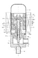
次に、本発明の電動弁の実施の形態を図面を参照して説明する。図1は第1実施形態の電動弁の縦断面図、図2は同電動弁の支持部材の三面図、図3は同電動弁のロータ軸の四面図、図4は同電動弁のマグネットロータの二面図である。なお、以下の説明における「上下」の概念は図1の図面における上下に対応する。この電動弁は、円筒形状の弁本体1を有している。弁本体1には、その片側端部に弁ポート1aが開口されている。また、弁本体1の弁ポート1aと反対側の開口部には「支持部」としての支持部材2が取り付けられている。これにより、弁本体1はその内側に弁室1bを形成している。弁本体1の外周片側には冷媒の流路としての第1継手管11が接続され、この第1継手管11は弁室1bに導通されている。また、弁ポート1a側には第2継手管12が接続され、この第2継手管12は弁ポート1aを介して弁室1bに導通される。なお、第1継手管11、第2継手管12及び支持部材2は、弁本体1に対して蝋付け等により固着されている。
Next, an embodiment of the motor-operated valve of the present invention will be described with reference to the drawings. 1 is a longitudinal sectional view of the motor-operated valve according to the first embodiment, FIG. 2 is a three-side view of a support member of the motor-operated valve, FIG. 3 is a four-side view of a rotor shaft of the motor-operated valve, and FIG. FIG. Note that the concept of “upper and lower” in the following description corresponds to the upper and lower sides in the drawing of FIG. This electric valve has a
支持部材2は中央のホルダ部21とこのホルダ部21の外周のフランジ部22とを有しており、フランジ部22により弁本体1に取り付けられている。ホルダ部21の中心には、弁ポート1aの軸Lと同軸の雌ネジ21aとそのネジ孔が形成されるとともに、弁ポート1aと反対側には雌ネジ21aのネジ孔の外周よりも径の大きな円筒状のスライド孔21bが形成されている。そして、この雌ネジ21aのネジ孔とスライド孔21bの中に円柱棒状のロータ軸3が配設されている。ロータ軸3はスライド孔21bに整合する大径部31とこの大径部31より径の小さな小径部32とを有し、さらに、この小径部32の下端には「弁体部」としてのニードル部33を備えている。小径部32の外周には雄ネジ32aが形成されており、この雄ネジ32aはホルダ部21の雌ネジ21aに螺合されている。なお、雌ネジ21aと雄ネジ32aは右ネジである。また、ロータ軸3の大径部31の上端部には後述の係合部Aを備えている。
The
弁本体1の上端には、モータ部としてのステッピングモータ4のケース41が溶接等によって気密に固定されている。ケース41内には外周部を多極に着磁されたマグネットロータ42が回転可能に設けられている。また、ケース41の外周には、ステータコイル43が配設されており、モータ部としてのステッピングモータ4は、ステータコイル43にパルス信号が与えられることにより、そのパルス数に応じてマグネットロータ42を回転させる。
A
マグネットロータ42は、係合部Aにおいてロータ軸3に係合固着されている。そして、マグネットロータ42の回転によってマグネットロータ42と共にロータ軸3が回転し、雄ネジ32aと雌ネジ21aのネジ送り作用により、ロータ軸3が軸L方向(上下)に移動してニードル部33が弁ポート1aに対して進退する。これにより、弁ポート1aの開度を変化させ、第1継手管11から第2継手管12へ流れる冷媒の流量、または第2継手管12から第1継手管11へ流れる冷媒の流量が制御される。
The
図2に示すように、支持部材2は合成樹脂により型成形されたものであり、ホルダ部21には、その上端部の外周縁に固定下端ストッパSD1が形成され、ホルダ部21の外周の上端には半径方向に突出した固定上端ストッパSU1が形成されている。この固定下端ストッパSD1と固定上端ストッパSU1は支持部材2の本体と一体に形成されている。
As shown in FIG. 2, the
図3に示すように、ロータ軸3は合成樹脂により型成形されたものであり、大径部31にはフランジ部31aが形成され、このフランジ部31aの一部は扇形に切り欠かれた位置出し部31bとされている。また、フランジ部31aの小径部32側の面(下面)には可動下端ストッパMD1がロータ軸3の本体と一体に形成されている。大径部31のニードル部33と反対側の係合部Aは、ロータ軸3の半径方向に弾性変形可能なフォーク状の2つの爪部材3a,3aを有している。この爪部材3a,3aの側面は円錐面とされるとともにフランジ部31a側の外周縁部3a1,3a1は半径方向に大径部31の径より僅かに突出している。
As shown in FIG. 3, the
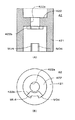
図4に示すように、マグネットロータ42は円柱状のマグネット部421とその内側の円盤部422とで構成されており、円盤部422の中心には、係合部Aとして、ロータ軸3の大径部31と同じ径の嵌合孔422aが形成されている。すなわち、前記ロータ軸3側の爪部材3a,3aの外周縁部3a1,3a1は、嵌合孔422aの径よりも僅かに外側に突出する形状となっている。また、マグネット部421の内周面の下端には、軸回りの1箇所に可動上端ストッパMU1が形成されている。この可動上端ストッパMU1は、マグネットロータ42の組み付け状態では、固定上端ストッパSU1よりも弁ポート1a側となる位置に形成されている。さらに、この可動上端ストッパMU1はマグネットロータ42と一体成形されている。そして、この可動上端ストッパMU1は内周側に突出しており、後述のようにマグネットロータ42が上昇したときに支持部材2の固定上端ストッパSU1に係合可能となっている。
As shown in FIG. 4, the
また、マグネットロータ42の円盤部422には、その一部に扇状に突出した位置出し部422bが形成されており、この位置出し部422bは前記ロータ軸3の位置出し部31bに係合され、ロータ軸3とマグネットロータ42との相対位置が決められる。
The
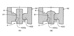
図5は固定下端ストッパSD1と可動下端ストッパMD1の作用を説明する図、図6は固定上端ストッパSU1と可動上端ストッパMU1の作用を説明する図である。ロータ軸3が回動して支持部材2側に移動(下降)するとき、流量を制御する制御範囲では、図5(A)に示すように可動下端ストッパMD1は固定下端ストッパSD1の上を通過し、制御範囲の下限になると、図5(B) に示すように、可動下端ストッパMD1が固定下端ストッパSD1に係合し、ロータ軸3の回動が規制される。また、ロータ軸3及びマグネットロータ42が回動して支持部材2と反対側に移動(上昇)するとき、制御範囲では、図6(A)に示すように可動上端ストッパMU1は固定上端ストッパSU1の下を通過し、制御範囲の上限になると、図6(B) に示すように、可動上端ストッパMU1が固定上端ストッパSU1に係合し、ロータ軸3の回動が規制される。
FIG. 5 is a diagram illustrating the operation of the fixed lower end stopper SD1 and the movable lower end stopper MD1, and FIG. 6 is a diagram illustrating the operation of the fixed upper end stopper SU1 and the movable upper end stopper MU1. When the
図7は第1実施形態の電動弁の動作を示す図であり、弁ポート1aの開度により流量を制御する制御範囲では、例えば図7(B) の状態にある。この状態からマグネットロータ42及びロータ軸3を下降すると図7(A) の状態になり、ロータ軸3の可動下端ストッパMD1が支持部材2の固定下端ストッパSD1に係合し、ロータ軸3の回動が停止するとともに、ニードル部33が弁ポート1aを最小絞り状態とする。一方、図7(B) の状態からマグネットロータ42及びロータ軸3を上昇すると図7(C) の状態になり、マグネットロータ42の可動上端ストッパMU1が支持部材2の固定上端ストッパSU1に係合し、ロータ軸3の回動が停止するとともに、ニードル部33が弁ポート1aを全開状態とする。
FIG. 7 is a diagram showing the operation of the motor-operated valve according to the first embodiment. In the control range in which the flow rate is controlled by the opening degree of the
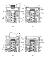
図8は支持部材2、ロータ軸3及びマグネットロータ42の組み付け方法を説明する図である。なお、図8(B) は図8(A) のC−C矢視図であり、この図8(B) においてはロータ軸3については可動下端ストッパMD1のみを一点鎖線で図示してある。先ず、図8(A) のように、支持部材2の雌ネジ21aのネジ孔にロータ軸3をねじ込み、支持部材2の固定上端ストッパSU1の下端からロータ軸3のフランジ部31aの上端までの寸法Aが、マグネットロータ42の可動上端ストッパMU1の上端から円盤部422の下端までの寸法Bよりも、小さくなるようにする。また、このとき、図8(B) のように、可動上端ストッパMU1が固定上端ストッパSU1に重ならない回動位置となるように、ロータ軸3の回動位置を決める。
FIG. 8 is a diagram illustrating a method for assembling the
そして、ロータ軸3の爪部材3a,3aをマグネットロータ42の嵌合孔422aに嵌め込むようにし、位置出し部422bを位置出し部31bに係合し、ロータ軸3とマグメットロータ42を係合して固着する。このとき、マグネットロータ42とロータ軸3及び支持部材2は相互に干渉するような部分はなく、容易に組み付けることができる。
Then, the
図9は固定下端ストッパSD1及び可動下端ストッパMD1の製作方法の一例を示す図である。なお、図9及び後述の図10は位置関係を概念的に示す図であり、例えば縦方向の長さの比率等は実寸とは異なっている。固定下端ストッパSD1は支持部材2の雌ネジ21aにおける基準位置O1からの距離D1によりその上端を設定し、可動下端ストッパMD1はロータ軸3の雄ネジ32aにおける基準位置O2からの距離D2によりその下端を設定する。この場合、D1−D2が接触高さになるが、この接触高さは、雌ネジ21a(及び雄ネジ32a)のピッチより小さくすることはいうまでもない。
FIG. 9 is a diagram illustrating an example of a manufacturing method of the fixed lower end stopper SD1 and the movable lower end stopper MD1. Note that FIG. 9 and FIG. 10 described later are diagrams conceptually showing the positional relationship. For example, the ratio of the length in the vertical direction is different from the actual size. The upper end of the fixed lower end stopper SD1 is set by the distance D1 from the reference position O1 of the
図10は固定上端ストッパSU1及び可動上端ストッパMU1の製作方法の一例を示す図である。固定上端ストッパSU1は支持部材2の雌ネジ21aにおける基準位置O1からの距離D3によりその下端を設定し、可動上端ストッパMU1はロータ軸3の雄ネジ32aにおける基準位置O2からフランジ部31aの上端面までの距離D4と、マグネットロータ42の円盤部422の下端面からの距離D5によりその上端を設定する。この場合、(D4−D5)−D3が接触高さになるが、この接触高さは、雌ネジ21a(及び雄ネジ32a)のピッチより小さくすることはいうまでもない。
FIG. 10 is a diagram illustrating an example of a manufacturing method of the fixed upper end stopper SU1 and the movable upper end stopper MU1. The fixed upper end stopper SU1 has its lower end set by a distance D3 from the reference position O1 of the
このように、支持部材2、ロータ軸3及びマグネットロータ42は合成樹脂の型成形により形成されているので、電動弁のロットにおいてのバラツキはなく、制御域の上端及び下端を規制するストッパ機構として精度よいものが得られる。なお、必要とする制御範囲のニードル部33の下端位置から上端位置までの距離は設計により決定されるので、この距離をネジのピッチで割れば回転数(小数を含む)を割り出すことができ、これにより、固定下端ストッパSD1、可動下端ストッパMD1、固定上端ストッパSU1及び可動上端ストッパMU1の位置を設定することができる。
As described above, since the
図11は第2実施形態の電動弁の縦断面図、図12は第2実施形態の電動弁における支持部材の要部を示す三面図、図13は第2実施形態の電動弁におけるロータ軸の要部を示す三面図である。なお、以下の実施形態で第1実施形態と同様な要素及び対応する要素には同符号を付記して重複する詳細な説明は省略する。この第2実施形態では、ロータ軸3のフランジ部31aの径を大きくし、可動下端ストッパMD2を第1実施形態の可動下端ストッパMD1よりも外側に配置し、さらに、支持部材2における固定下端ストッパSD2を第1実施形態の固定下端ストッパSD1よりも外側に配置したものである。なお、可動上端ストッパMU1及び固定上端ストッパSU1は第1実施形態と同様である。
FIG. 11 is a longitudinal sectional view of the motor-operated valve of the second embodiment, FIG. 12 is a three-plane view showing the main part of the support member in the motor-operated valve of the second embodiment, and FIG. It is a three-view figure which shows the principal part. In the following embodiments, the same elements as those in the first embodiment and the corresponding elements are denoted by the same reference numerals, and detailed description thereof is omitted. In the second embodiment, the diameter of the
この第2実施形態によれば、第1実施形態に比べて、下端位置での可動下端ストッパMD2及び固定下端ストッパSD2に作用するトルクを低減できる。 According to the second embodiment, the torque acting on the movable lower end stopper MD2 and the fixed lower end stopper SD2 at the lower end position can be reduced as compared with the first embodiment.
図14は第3実施形態の電動弁の縦断面図、図15は第3実施形態の電動弁におけるマグネットロータの二面図である。この第3実施形態における支持部材2は第2実施形態と同様であり、第2実施形態におけるロータ軸3に形成した可動下端ストッパMD2の代わりに、マグネットロータ42に可動下端ストッパMD3を形成したものである。この場合にも第2実施形態と同様に、下端位置での可動下端ストッパMD3及び固定下端ストッパSD2に作用するトルクを低減できる。
FIG. 14 is a longitudinal sectional view of the motor-operated valve according to the third embodiment, and FIG. 15 is a two-side view of the magnet rotor in the motor-operated valve according to the third embodiment. The
図16は第4実施形態の電動弁の縦断面図、図17は第4実施形態の電動弁における支持部材の要部を示す三面図、図18は第4実施形態の電動弁におけるマグネットロータの二面図である。この第4実施形態では、固定下限ストッパSD4を支持部材2の外周の下端に設け、可動下端ストッパMD4と可動上端ストッパMU4をマグネットロータ42の内周面の一つの突起として一体に設けたものである。
FIG. 16 is a longitudinal sectional view of the motor-operated valve of the fourth embodiment, FIG. 17 is a three-plane view showing the main part of the support member in the motor-operated valve of the fourth embodiment, and FIG. 18 is a diagram of the magnet rotor in the motor-operated valve of the fourth embodiment. FIG. In the fourth embodiment, the fixed lower limit stopper SD4 is provided at the lower end of the outer periphery of the
図19は第5実施形態の電動弁の縦断面図、図20は第5実施形態の電動弁における支持部材の雌ネジ及びロータ軸の雄ネジを示す図である。この第5実施形態では、固定上端ストッパSU1及び可動上端ストッパMU1は第1実施形態と同様である。固定下端ストッパSD5は支持部材2の雌ネジ21aの端部を壁状にして形成し、可動下端ストッパMD5はロータ軸3の雄ネジ32aの端部を壁状にして形成したものである。
FIG. 19 is a longitudinal sectional view of the motor-operated valve according to the fifth embodiment, and FIG. 20 is a diagram showing the female screw of the support member and the male screw of the rotor shaft in the motor-operated valve of the fifth embodiment. In the fifth embodiment, the fixed upper end stopper SU1 and the movable upper end stopper MU1 are the same as in the first embodiment. The fixed lower end stopper SD5 is formed with the end of the
図21〜23は係合部Aの他の実施形態を示す図であり、図21の係合部Aはロータ軸3の大径部31の端部の外周に溝3bを形成したものである。そして、マグネットロータ42の嵌合孔422a内に大径部31を嵌挿し、リング状のクリップ3cを溝3bに嵌め込んでロータ軸3とマグネットロータ42を固着する。
21 to 23 are views showing other embodiments of the engaging portion A, and the engaging portion A in FIG. 21 has a
図22の係合部Aの例は、図22(A) のように、ロータ軸3の大径部31をマグネットロータ42の嵌合孔422aに嵌挿され、図22(B) のように、この係合部Aが熱かしめされ、マグネットロータ42とロータ軸3とが互いに嵌合固着されている。
22A and 22B, the large-
図23の係合部Aの例は、ロータ軸3の大径部31の端部の外周に、大径部31の外周半径方向に嵌合孔422aの径よりも僅かに突出する突起部3dが形成されている。そして、マグネットロータ42の嵌合孔422aにロータ軸3の大径部31の端部が突起部3dを弾性変形させて圧入されている。これにより、マグネットロータ42とロータ軸3とが互いに嵌合固着されている。
In the example of the engaging portion A in FIG. 23, a protruding
以上の各係合部Aは、前記ストッパ機構に関する各実施形態の何れにも適用できることはいうまでもない。 Needless to say, each of the above engaging portions A can be applied to any of the embodiments related to the stopper mechanism.
図24は第6実施形態の電動弁の縦断面図である。この第6実施形態ではロータ軸3を金属製の芯棒3Aとその周囲の樹脂部3Bとで構成したものであり、このロータ軸3はインサート成形して形成されている。その他の構造は第1実施形態と同様である。この実施形態によれば、ロータ軸3の成形時の反りを低減することができ、作動を確実にしてより信頼性が高まる。また、この実施形態のようにニードル部33を芯棒3Aで兼ねることもできる。
FIG. 24 is a longitudinal sectional view of a motor operated valve according to the sixth embodiment. In the sixth embodiment, the
図25は第7実施形態の電動弁の縦断面図である。この第7実施形態と前記各実施形態との違いは、マグネットロータ42とロータ軸5の固着構造にある。また、この第7実施形態ではロータ軸5と弁棒6を一体にせずに、ロータ軸5に対して弁棒6が軸L方向に移動可能になっている点にある。
FIG. 25 is a longitudinal sectional view of the motor operated valve according to the seventh embodiment. The difference between the seventh embodiment and each of the embodiments described above is in the fixing structure of the
ロータ軸5は合成樹脂により型成形されたものであり、このロータ軸5は支持部材2のスライド孔21bに整合する大径部51とこの大径部51より径の小さな小径部52とを有している。大径部51にはフランジ部51aとが形成されるとともに、このフランジ部51aの面(下面)には可動下端ストッパMD1が形成されている。また、小径部52の外周には雄ネジ52aが形成されている。そして、雄ネジ52aがホルダ部21の雌ネジ21aに螺合されている。さらに、小径部52を貫通するように弁棒6が配設されており、この弁棒6は、その下端に「弁体部」としてのニードル部61を備えている。
The
なお、ホルダ部21の固定下端ストッパSD1、固定上端ストッパSU1、可動下端ストッパMD1及び可動上端ストッパMU1の作用は第1実施形態と同様である。
The operations of the fixed lower end stopper SD1, the fixed upper end stopper SU1, the movable lower end stopper MD1, and the movable upper end stopper MU1 of the
ロータ軸5には弁体部61と反対側の端部に下穴5aが形成されており、この下穴5aの上端部分に,取付金具7が配設されている。取付金具7は、マグネットロータ42の円板部422の中心に形成された嵌合孔422aより大なるフランジ部71と、ロータ軸5の下穴5aより大なるインサート部72から構成されており、インサート部72の周囲はローレット加工によりあやめローレットが形成されている。そして、インサート部72が下穴5aに圧入され、フランジ部71が嵌合孔422aの周囲に当接され、このフランジ部71とロータ軸5のフランジ部51aとによりマグネットロータ42が挟まれている。これにより、マグネットロータ42とロータ軸5とが互いに嵌合固着されている。
The
ロータ軸5の下穴5a内にはコイルばね62が配設されており、このコイルばねの付勢力により弁棒6は弁ポート1a側に付勢されており、この第7実施形態では、可動下端ストッパMD1が固定下端ストッパSD1に当接する直前にニードル部61が弁ポート1aを全閉とする。そして、可動下端ストッパMD1が固定下端ストッパSD1に当接するまで、コイルばね62が僅かに圧縮される。
A
図26はロータ軸5とマグネットロータ42を固着する手順を示す図である。まず、図26(A) のように、下穴5a内に弁棒6とコイルばね62をセットする。次に、図26(B) のように取付金具7のインサート部72の先端を下穴5aに挿入する。そして、図26(C) のように、加熱治具Bにより取付金具7を加熱及び押圧し、図26(D) のようにフランジ部71をマグネットロータ42の円板部422に当接させる。
FIG. 26 is a diagram showing a procedure for fixing the
図27〜図30は取付金具7の変形例を示す図である。図27の取付金具7はフランジ部71とインサート部72を有し、このインサート部72の周囲にローレット加工によりスパイラルローレットを形成したものである。図28の取付金具7は板金のプレス加工によりフランジ部71とインサート部72を形成し、このインサート部72の周囲に突状の爪72aを形成したものである。図29の取付金具7は板金のプレス加工によりフランジ部71とインサート部72を形成し、このインサート部72の周囲に板状の爪72aを形成したものである。図30の取付金具7は板金の打ち抜き及び曲げ加工によりフランジ部71とインサート部72を形成したものであり、このインサート部72を巻きブッシュ形状としたものである。これら図27〜図30の取付金具7も図25に示す取付金具7と同様にロータ軸5の下穴5a内にインサート部72を嵌合し、ロータ軸5とマグネットロータ42とを嵌合固着する。
27-30 is a figure which shows the modification of the
また、取付金具のインサート部の周囲に雄ネジを形成し、ロータ軸の下穴に雌ネジを形成し、取付金具をロータ軸の下穴にネジ止めするようにしてもよい。 Further, a male screw may be formed around the insert portion of the mounting bracket, a female screw may be formed in the pilot hole of the rotor shaft, and the mounting bracket may be screwed to the pilot hole of the rotor shaft.
以上の第7実施形態のように取付家具7によりロータ軸5とマグネットロータ42とを嵌合固着する構造は、前記第1〜第6実施形態の何れの構造にも適用できる。また、第7実施形態の可動下端ストッパMD1、固定下端ストッパSD1、可動下端ストッパMD1及び固定下端ストッパSD1は第1実施形態と同様であるが、その他の実施形態のストッパの構造を第7実施形態に適用することもできる。
The structure in which the
1 弁本体
1a 弁ポート
1b 弁室
2 支持部材
21 ホルダ部
21a 雌ネジ
3 ロータ軸
31 大径部
32 小径部
32a 雄ネジ
33 ニードル部
4 ステッピングモータ
42 マグネットロータ
422a 嵌合孔
5 ロータ軸
5a 下穴
6 弁棒
7 取付金具
71 フランジ部
72 インサート部
SD1 固定下端ストッパ
MD1 可動下端ストッパ
SU1 固定上端ストッパ
MU1 可動上端ストッパ
DESCRIPTION OF
Claims (11)
前記支持部には軸回りの1箇所に固定下端ストッパが形成され、前記ロータ軸または前記マグネットロータには軸回りの1箇所に該固定下端ストッパに係合可能な可動下端ストッパが形成され、
さらに前記支持部には、前記マグネットロータの内周に対向する該支持部の外周の1箇所に固定上端ストッパが一体成形され、前記マグネットロータには、該固定上端ストッパに係合可能な可動上端ストッパが、該固定上端ストッパよりも前記弁ポート側となる該マグネットロータの内周の1箇所に一体成形され、
前記ロータ軸のネジ送り作用にて前記弁体部を弁ポート側に移動したときに、前記固定下端ストッパに前記可動下端ストッパを係合させて、該弁体部の下端位置を規制するとともに、該ネジ送り作用にて該弁体部を弁ポートと反対側に移動したときに、前記固定上端ストッパに前記可動上端ストッパを係合させて、該弁体部の上端位置を規制するように構成され、
前記マグネットロータと前記ロータ軸とが別部材であって、該マグネットロータと該ロータ軸とが、該ロータ軸の前記弁体部側と 反対側端部に対して該マグネットロータを嵌合可能となる形状にそれぞれ形成され、該マグネットロータとロータ軸とが互いに嵌合固着することで組み立てられていることを特徴とする電動弁。 A support portion disposed opposite to the valve port with respect to the valve chamber having the valve port, the support portion having a female screw formed coaxially with the shaft of the valve port, and a female screw of the support portion A rotor shaft having a male screw on the outer periphery to be screwed, a magnet rotor fixed to the rotor shaft and covering a part of the support portion, and a motor portion disposed on the outer periphery of the magnet rotor. By rotating the magnet rotor and the rotor shaft, the valve body provided at the end of the rotor shaft is advanced and retracted with respect to the valve port by the screw feeding action of the rotor shaft, and the fluid passing through the valve port In the motorized valve designed to control the flow rate of
A fixed lower end stopper is formed at one place around the shaft in the support part, and a movable lower end stopper that can be engaged with the fixed lower end stopper is formed at one place around the shaft in the rotor shaft or the magnet rotor.
Further, a fixed upper end stopper is integrally formed on the support portion at one location on the outer periphery of the support portion facing the inner periphery of the magnet rotor, and the movable upper end engageable with the fixed upper end stopper is formed on the magnet rotor. A stopper is integrally formed at one location on the inner periphery of the magnet rotor that is closer to the valve port than the fixed upper end stopper,
When the valve body portion is moved to the valve port side by the screw feeding action of the rotor shaft, the movable lower end stopper is engaged with the fixed lower end stopper, and the lower end position of the valve body portion is regulated. The movable upper end stopper is engaged with the fixed upper end stopper to restrict the upper end position of the valve body portion when the valve body portion is moved to the opposite side of the valve port by the screw feeding action. And
The magnet rotor and the rotor shaft are separate members, and the magnet rotor and the rotor shaft can be fitted to the end of the rotor shaft opposite to the valve body side. A motor-operated valve characterized in that each of the magnet rotors and the rotor shaft are assembled and fixed together.
前記マグネットロータの前記嵌合孔に前記ロータ軸の前記爪部材を弾性変形させて嵌合されることで、該マグネットロータと該ロータ軸とが互いに嵌合固着されていることを特徴とする請求項2に記載の電動弁。 The magnet rotor is formed with a fitting hole at the center, and the rotor shaft is elastically deformable in the radial direction of the rotor shaft at the end opposite to the valve body, and the end is the fitting hole. A plurality of claw members protruding outward slightly from the diameter of
The magnet rotor and the rotor shaft are fitted and fixed to each other by elastically deforming the claw member of the rotor shaft into the fitting hole of the magnet rotor. Item 3. The motor-operated valve according to Item 2.
前記マグネットロータの前記嵌合孔に前記ロータ軸の前記端部を嵌合されるとともに、前記溝にリング状のクリップが係合されることで、該マグネットロータと該ロータ軸とが互いに嵌合固着されていることを特徴とする請求項2に記載の電動弁。 A fitting hole is formed at the center of the magnet rotor, and a groove is formed on the outer periphery of the end opposite to the valve body portion on the rotor shaft.
The magnet rotor and the rotor shaft are fitted to each other by fitting the end of the rotor shaft into the fitting hole of the magnet rotor and engaging a ring-shaped clip with the groove. The motor-operated valve according to claim 2, wherein the motor-operated valve is fixed.
前記マグネットロータの前記嵌合孔に前記ロータ軸の前記突起部を弾性変形させて圧入されることで、該マグネットロータと該ロータ軸とが互いに嵌合固着されていることを特徴とする請求項2に記載の電動弁。 A fitting hole is formed at the center of the magnet rotor, and the rotor shaft is slightly outer than the fitting hole in the outer peripheral radial direction of the rotor shaft on the outer periphery of the end opposite to the valve body portion. A protruding part is formed,
The magnet rotor and the rotor shaft are fitted and fixed to each other by being press-fitted into the fitting hole of the magnet rotor by elastically deforming the protrusion of the rotor shaft. 2. The electric valve according to 2.
該嵌合孔より大なるフランジ部と該下穴より大なるインサート部からなる取付金具を、該インサート部を該下穴に圧入またはネジ止めするとともに該フランジ部を該嵌合孔の周囲に当接させることで、該マグネットロータと該ロータ軸とが互いに嵌合固着されていることを特徴とする請求項2に記載の電動弁。 The magnet rotor is formed with a fitting hole in the center, and the rotor shaft has a pilot hole at the end opposite to the valve body portion,
A mounting bracket comprising a flange portion larger than the fitting hole and an insert portion larger than the pilot hole is press-fitted or screwed into the pilot hole and the flange portion is applied to the periphery of the fitting hole. The motor-operated valve according to claim 2, wherein the magnet rotor and the rotor shaft are fitted and fixed to each other by being brought into contact with each other.
Priority Applications (2)
| Application Number | Priority Date | Filing Date | Title |
|---|---|---|---|
| JP2009030796A JP4669051B2 (en) | 2008-07-16 | 2009-02-13 | Motorized valve |
| CN 200910151775 CN101629649B (en) | 2008-07-16 | 2009-07-15 | Electric valve |
Applications Claiming Priority (2)
| Application Number | Priority Date | Filing Date | Title |
|---|---|---|---|
| JP2008184395 | 2008-07-16 | ||
| JP2009030796A JP4669051B2 (en) | 2008-07-16 | 2009-02-13 | Motorized valve |
Publications (2)
| Publication Number | Publication Date |
|---|---|
| JP2010043727A true JP2010043727A (en) | 2010-02-25 |
| JP4669051B2 JP4669051B2 (en) | 2011-04-13 |
Family
ID=41574869
Family Applications (1)
| Application Number | Title | Priority Date | Filing Date |
|---|---|---|---|
| JP2009030796A Active JP4669051B2 (en) | 2008-07-16 | 2009-02-13 | Motorized valve |
Country Status (2)
| Country | Link |
|---|---|
| JP (1) | JP4669051B2 (en) |
| CN (1) | CN101629649B (en) |
Cited By (33)
| Publication number | Priority date | Publication date | Assignee | Title |
|---|---|---|---|---|
| JP2010169173A (en) * | 2009-01-22 | 2010-08-05 | Fuji Koki Corp | Motor-driven valve |
| CN101858455A (en) * | 2010-06-04 | 2010-10-13 | 烟台冰轮高压氧舱有限公司 | Electric control valve |
| JP2011208716A (en) * | 2010-03-30 | 2011-10-20 | Fuji Koki Corp | Electric valve |
| CN102297189A (en) * | 2010-06-25 | 2011-12-28 | 株式会社不二工机 | Female screw member, motor operated valve using same, and method for producing female screw member for motor operated valve |
| JP2012007682A (en) * | 2010-06-25 | 2012-01-12 | Fuji Koki Corp | Female screw member, motor operated valve using the same, and method of manufacturing female screw member for motor operated valve |
| JP2012013095A (en) * | 2010-06-29 | 2012-01-19 | Fuji Koki Corp | Motor operated valve |
| JP2012062961A (en) * | 2010-09-16 | 2012-03-29 | Fuji Koki Corp | Motor-operated valve |
| JP2013133914A (en) * | 2011-12-27 | 2013-07-08 | Saginomiya Seisakusho Inc | Control valve |
| JP2013221578A (en) * | 2012-04-17 | 2013-10-28 | Rinnai Corp | Flow rate regulation valve |
| JP2013539849A (en) * | 2010-10-15 | 2013-10-28 | 浙江三花股▲ふん▼有限公司 | Motorized valve |
| JP2014088029A (en) * | 2011-12-07 | 2014-05-15 | Saginomiya Seisakusho Inc | Insert molding method for integrating female screw member via insert molding |
| JP2016156439A (en) * | 2015-02-24 | 2016-09-01 | 株式会社不二工機 | Electric valve |
| JP2016164434A (en) * | 2015-03-06 | 2016-09-08 | 株式会社鷺宮製作所 | Motor valve |
| JP2019002572A (en) * | 2018-10-10 | 2019-01-10 | 株式会社不二工機 | Electrical drive valve |
| KR20190027896A (en) * | 2016-07-13 | 2019-03-15 | 스톤 마운틴 테크놀로지스, 인크. | An electronic expansion valve having a plurality of orifice plates |
| CN110159821A (en) * | 2018-02-13 | 2019-08-23 | 株式会社鹭宫制作所 | Motor-driven valve and refrigerating circulation system |
| CN110529606A (en) * | 2018-05-25 | 2019-12-03 | 浙江三花智能控制股份有限公司 | Electric expansion valve |
| JP2020076485A (en) * | 2018-11-08 | 2020-05-21 | 株式会社不二工機 | Passage switching valve |
| KR20200057149A (en) * | 2018-11-15 | 2020-05-26 | 우리산업 주식회사 | Electronic expansion valve |
| KR20200059371A (en) * | 2018-11-20 | 2020-05-29 | 우리산업 주식회사 | Electronic expansion valve |
| JP2020122576A (en) * | 2020-04-09 | 2020-08-13 | 株式会社鷺宮製作所 | Motor valve and refrigeration cycle system |
| EP3696453A1 (en) * | 2019-02-14 | 2020-08-19 | TGK CO., Ltd. | Motor operated valve |
| US10948099B2 (en) | 2019-02-14 | 2021-03-16 | Tgk Co., Ltd. | Motor operated valve |
| EP3845789A1 (en) * | 2019-12-31 | 2021-07-07 | Kyungdong Navien Co., Ltd. | Valve for water flow control |
| JP2021110460A (en) * | 2019-12-31 | 2021-08-02 | キュンドン ナビエン シーオー.,エルティーディー. | Flow control valve |
| CN113606146A (en) * | 2021-09-16 | 2021-11-05 | 珠海格力节能环保制冷技术研究中心有限公司 | Air suction check assembly and scroll compressor comprising same |
| KR20220024970A (en) * | 2019-08-21 | 2022-03-03 | 제지앙 둔안 아트피셜 인바이런먼트 컴퍼니 리미티드 | Electronic expansion valve and its installation method |
| WO2022098251A1 (en) * | 2020-11-03 | 2022-05-12 | Institutul Naţional De Cercetare Dezvoltare Pentru Inginerie Electrică Icpe-Ca | Equipment for continuous adjustment of liquid flow, with direct electric drive of the element which performs the modification of the flow section |
| KR20220088500A (en) * | 2019-11-19 | 2022-06-27 | 제지앙 둔안 아트피셜 인바이런먼트 컴퍼니 리미티드 | Magnetic rotor assembly and electronic expansion valve |
| WO2022185824A1 (en) * | 2021-03-04 | 2022-09-09 | 株式会社不二工機 | Flow rate control valve |
| JP2022190566A (en) * | 2021-06-14 | 2022-12-26 | 株式会社不二工機 | Motor valve |
| EP3957881A4 (en) * | 2019-06-12 | 2023-01-18 | Zhejiang Dunan Artificial Environment Co., Ltd. | Electronic expansion valve |
| JP7429290B2 (en) | 2019-11-19 | 2024-02-07 | 浙江盾安人工環境股▲ふん▼有限公司 | electronic expansion valve |
Families Citing this family (18)
| Publication number | Priority date | Publication date | Assignee | Title |
|---|---|---|---|---|
| JP5130339B2 (en) * | 2010-10-05 | 2013-01-30 | 株式会社鷺宮製作所 | Motorized valve |
| CN102213509B (en) * | 2011-06-02 | 2017-04-12 | 上海俊乐制冷自控元件有限公司 | Electronic expansion valve |
| CN102287536B (en) * | 2011-07-27 | 2013-03-20 | 浙江盾安禾田金属有限公司 | Electronic expansion valve |
| DE102012208352A1 (en) * | 2012-05-18 | 2013-11-21 | Robert Bosch Gmbh | Method for connecting two battery poles of two battery cells consisting of dissimilar materials and battery unit |
| CN104132149B (en) * | 2013-05-02 | 2017-09-01 | 浙江三花智能控制股份有限公司 | A kind of motor-driven valve |
| CN108980378A (en) * | 2014-06-17 | 2018-12-11 | 浙江盾安人工环境股份有限公司 | Electric expansion valve |
| CN104165233B (en) * | 2014-06-23 | 2018-02-09 | 珠海格力电器股份有限公司 | Enter flow structure and pressure drop device and air conditioner |
| JP6214488B2 (en) * | 2014-07-18 | 2017-10-18 | 株式会社鷺宮製作所 | Motorized valve |
| JP6419482B2 (en) * | 2014-08-06 | 2018-11-07 | 株式会社不二工機 | Electrically driven valve |
| JP6240243B2 (en) * | 2016-03-07 | 2017-11-29 | 株式会社鷺宮製作所 | Motorized valve and motorized valve manufacturing method |
| JP6651437B2 (en) * | 2016-12-27 | 2020-02-19 | 株式会社鷺宮製作所 | Motorized valve |
| CN108662169B (en) * | 2017-03-27 | 2021-12-21 | 盾安环境技术有限公司 | Electronic expansion valve |
| JP7023737B2 (en) * | 2018-02-21 | 2022-02-22 | 株式会社鷺宮製作所 | Solenoid valve and refrigeration cycle system |
| CN112413147B (en) * | 2019-08-21 | 2022-12-23 | 浙江盾安禾田金属有限公司 | Electronic expansion valve and processing method thereof |
| CN111963695B (en) * | 2020-07-28 | 2022-01-25 | 东风汽车集团有限公司 | Automobile-used electronic expansion valve and vehicle of low wear structure |
| CN212959909U (en) * | 2020-08-31 | 2021-04-13 | 盾安环境技术有限公司 | Electronic expansion valve |
| CN114110188B (en) * | 2020-08-31 | 2024-01-23 | 盾安环境技术有限公司 | Method for assembling electronic expansion valve and electronic expansion valve |
| CN114458773B (en) * | 2020-10-21 | 2024-03-29 | 盾安环境技术有限公司 | Electronic expansion valve |
Citations (23)
| Publication number | Priority date | Publication date | Assignee | Title |
|---|---|---|---|---|
| JPS54134864U (en) * | 1978-03-10 | 1979-09-19 | ||
| JPS55109175U (en) * | 1979-01-29 | 1980-07-31 | ||
| JPS57159361U (en) * | 1981-03-31 | 1982-10-06 | ||
| JPS6228173U (en) * | 1985-08-06 | 1987-02-20 | ||
| JPH01169677U (en) * | 1988-05-23 | 1989-11-30 | ||
| JPH0211981A (en) * | 1988-06-30 | 1990-01-17 | Toshiba Corp | Pulse motor driving valve |
| JPH0669069U (en) * | 1993-03-12 | 1994-09-27 | 日野車体工業株式会社 | Freight vehicle carrier |
| JPH084931A (en) * | 1994-06-15 | 1996-01-12 | Hitachi Ltd | Electric flow rate adjusting valve, and flow rate control device having the same |
| JPH09109268A (en) * | 1995-10-20 | 1997-04-28 | Nippon Plast Co Ltd | Joined structure and staking tool |
| JPH09310777A (en) * | 1996-05-24 | 1997-12-02 | Tgk Co Ltd | Flow control valve |
| JPH09317925A (en) * | 1996-05-31 | 1997-12-12 | Fuji Koki:Kk | Motor operated valve |
| JPH1047517A (en) * | 1996-08-05 | 1998-02-20 | Fuji Koki:Kk | Electrically operated valve |
| JPH10220614A (en) * | 1997-02-05 | 1998-08-21 | Denso Corp | Electric control valve |
| JP2000002355A (en) * | 1998-04-13 | 2000-01-07 | Tgk Co Ltd | Motor-operated valve |
| JP2001050415A (en) * | 1999-06-02 | 2001-02-23 | Fuji Koki Corp | Electrically driven valve |
| JP2001260338A (en) * | 2000-03-22 | 2001-09-25 | Seiko Epson Corp | Ink jet recorder and method of manufacture |
| JP3310042B2 (en) * | 1993-02-16 | 2002-07-29 | 株式会社不二工機 | Rotor center body for motor-operated valve, rotor feed screw, and method of manufacturing rotor |
| JP2003013933A (en) * | 2001-06-28 | 2003-01-15 | Hikari Kairiku Sangyo Kk | Fastener |
| JP2004239428A (en) * | 2003-01-17 | 2004-08-26 | Saginomiya Seisakusho Inc | Motor operated valve |
| JP2006029435A (en) * | 2004-07-15 | 2006-02-02 | Saginomiya Seisakusho Inc | Electric control valve and refrigeration cycle device |
| JP2006307975A (en) * | 2005-04-28 | 2006-11-09 | Fuji Koki Corp | Motor-operated valve |
| JP2007032675A (en) * | 2005-07-26 | 2007-02-08 | Fuji Koki Corp | Motor operated valve |
| JP2007139016A (en) * | 2005-11-16 | 2007-06-07 | Saginomiya Seisakusho Inc | Electric motor-driven type control valve and refrigerating cycle device |
Family Cites Families (2)
| Publication number | Priority date | Publication date | Assignee | Title |
|---|---|---|---|---|
| JPH10215545A (en) * | 1997-01-28 | 1998-08-11 | Mitsubishi Electric Corp | Rotary motion/linear motion converting motor |
| CN2846913Y (en) * | 2005-12-08 | 2006-12-13 | 浙江中宝自控元件有限公司 | Electronic expansion valve |
-
2009
- 2009-02-13 JP JP2009030796A patent/JP4669051B2/en active Active
- 2009-07-15 CN CN 200910151775 patent/CN101629649B/en active Active
Patent Citations (23)
| Publication number | Priority date | Publication date | Assignee | Title |
|---|---|---|---|---|
| JPS54134864U (en) * | 1978-03-10 | 1979-09-19 | ||
| JPS55109175U (en) * | 1979-01-29 | 1980-07-31 | ||
| JPS57159361U (en) * | 1981-03-31 | 1982-10-06 | ||
| JPS6228173U (en) * | 1985-08-06 | 1987-02-20 | ||
| JPH01169677U (en) * | 1988-05-23 | 1989-11-30 | ||
| JPH0211981A (en) * | 1988-06-30 | 1990-01-17 | Toshiba Corp | Pulse motor driving valve |
| JP3310042B2 (en) * | 1993-02-16 | 2002-07-29 | 株式会社不二工機 | Rotor center body for motor-operated valve, rotor feed screw, and method of manufacturing rotor |
| JPH0669069U (en) * | 1993-03-12 | 1994-09-27 | 日野車体工業株式会社 | Freight vehicle carrier |
| JPH084931A (en) * | 1994-06-15 | 1996-01-12 | Hitachi Ltd | Electric flow rate adjusting valve, and flow rate control device having the same |
| JPH09109268A (en) * | 1995-10-20 | 1997-04-28 | Nippon Plast Co Ltd | Joined structure and staking tool |
| JPH09310777A (en) * | 1996-05-24 | 1997-12-02 | Tgk Co Ltd | Flow control valve |
| JPH09317925A (en) * | 1996-05-31 | 1997-12-12 | Fuji Koki:Kk | Motor operated valve |
| JPH1047517A (en) * | 1996-08-05 | 1998-02-20 | Fuji Koki:Kk | Electrically operated valve |
| JPH10220614A (en) * | 1997-02-05 | 1998-08-21 | Denso Corp | Electric control valve |
| JP2000002355A (en) * | 1998-04-13 | 2000-01-07 | Tgk Co Ltd | Motor-operated valve |
| JP2001050415A (en) * | 1999-06-02 | 2001-02-23 | Fuji Koki Corp | Electrically driven valve |
| JP2001260338A (en) * | 2000-03-22 | 2001-09-25 | Seiko Epson Corp | Ink jet recorder and method of manufacture |
| JP2003013933A (en) * | 2001-06-28 | 2003-01-15 | Hikari Kairiku Sangyo Kk | Fastener |
| JP2004239428A (en) * | 2003-01-17 | 2004-08-26 | Saginomiya Seisakusho Inc | Motor operated valve |
| JP2006029435A (en) * | 2004-07-15 | 2006-02-02 | Saginomiya Seisakusho Inc | Electric control valve and refrigeration cycle device |
| JP2006307975A (en) * | 2005-04-28 | 2006-11-09 | Fuji Koki Corp | Motor-operated valve |
| JP2007032675A (en) * | 2005-07-26 | 2007-02-08 | Fuji Koki Corp | Motor operated valve |
| JP2007139016A (en) * | 2005-11-16 | 2007-06-07 | Saginomiya Seisakusho Inc | Electric motor-driven type control valve and refrigerating cycle device |
Cited By (49)
| Publication number | Priority date | Publication date | Assignee | Title |
|---|---|---|---|---|
| JP2010169173A (en) * | 2009-01-22 | 2010-08-05 | Fuji Koki Corp | Motor-driven valve |
| JP2011208716A (en) * | 2010-03-30 | 2011-10-20 | Fuji Koki Corp | Electric valve |
| CN101858455A (en) * | 2010-06-04 | 2010-10-13 | 烟台冰轮高压氧舱有限公司 | Electric control valve |
| CN102297189B (en) * | 2010-06-25 | 2015-07-15 | 株式会社不二工机 | Female screw member, motor operated valve using same, and method for producing female screw member for motor operated valve |
| CN102297189A (en) * | 2010-06-25 | 2011-12-28 | 株式会社不二工机 | Female screw member, motor operated valve using same, and method for producing female screw member for motor operated valve |
| JP2012007682A (en) * | 2010-06-25 | 2012-01-12 | Fuji Koki Corp | Female screw member, motor operated valve using the same, and method of manufacturing female screw member for motor operated valve |
| JP2012007683A (en) * | 2010-06-25 | 2012-01-12 | Fuji Koki Corp | Female screw member, motor-operated valve using the same, and manufacturing method for female screw member for motor-operated valve |
| KR101772700B1 (en) * | 2010-06-29 | 2017-08-29 | 가부시기가이샤 후지고오키 | Motor operated valve |
| JP2012013095A (en) * | 2010-06-29 | 2012-01-19 | Fuji Koki Corp | Motor operated valve |
| JP2012062961A (en) * | 2010-09-16 | 2012-03-29 | Fuji Koki Corp | Motor-operated valve |
| JP2013539849A (en) * | 2010-10-15 | 2013-10-28 | 浙江三花股▲ふん▼有限公司 | Motorized valve |
| JP2014088029A (en) * | 2011-12-07 | 2014-05-15 | Saginomiya Seisakusho Inc | Insert molding method for integrating female screw member via insert molding |
| JP2013133914A (en) * | 2011-12-27 | 2013-07-08 | Saginomiya Seisakusho Inc | Control valve |
| JP2013221578A (en) * | 2012-04-17 | 2013-10-28 | Rinnai Corp | Flow rate regulation valve |
| JP2016156439A (en) * | 2015-02-24 | 2016-09-01 | 株式会社不二工機 | Electric valve |
| JP2016164434A (en) * | 2015-03-06 | 2016-09-08 | 株式会社鷺宮製作所 | Motor valve |
| US11162719B2 (en) | 2016-07-13 | 2021-11-02 | Stone Mountain Technologies, Inc. | Electronic expansion valves having multiple orifice plates |
| KR20190027896A (en) * | 2016-07-13 | 2019-03-15 | 스톤 마운틴 테크놀로지스, 인크. | An electronic expansion valve having a plurality of orifice plates |
| JP2019521307A (en) * | 2016-07-13 | 2019-07-25 | ストーン・マウンテン・テクノロジーズ,インコーポレーテッド | Electronic expansion valve with multiple orifice plates |
| KR102173688B1 (en) * | 2016-07-13 | 2020-11-02 | 스톤 마운틴 테크놀로지스, 인크. | Electronic expansion valve with multiple orifice plates |
| CN110159821A (en) * | 2018-02-13 | 2019-08-23 | 株式会社鹭宫制作所 | Motor-driven valve and refrigerating circulation system |
| CN110529606A (en) * | 2018-05-25 | 2019-12-03 | 浙江三花智能控制股份有限公司 | Electric expansion valve |
| CN110529606B (en) * | 2018-05-25 | 2022-04-29 | 浙江三花智能控制股份有限公司 | Electronic expansion valve |
| JP2019002572A (en) * | 2018-10-10 | 2019-01-10 | 株式会社不二工機 | Electrical drive valve |
| JP7105489B2 (en) | 2018-11-08 | 2022-07-25 | 株式会社不二工機 | Flow switching valve |
| JP2020076485A (en) * | 2018-11-08 | 2020-05-21 | 株式会社不二工機 | Passage switching valve |
| KR102170493B1 (en) * | 2018-11-15 | 2020-10-29 | 우리산업 주식회사 | Electronic expansion valve |
| KR20200057149A (en) * | 2018-11-15 | 2020-05-26 | 우리산업 주식회사 | Electronic expansion valve |
| KR102170491B1 (en) * | 2018-11-20 | 2020-10-29 | 우리산업 주식회사 | Electronic expansion valve |
| KR20200059371A (en) * | 2018-11-20 | 2020-05-29 | 우리산업 주식회사 | Electronic expansion valve |
| EP3696453A1 (en) * | 2019-02-14 | 2020-08-19 | TGK CO., Ltd. | Motor operated valve |
| US10948099B2 (en) | 2019-02-14 | 2021-03-16 | Tgk Co., Ltd. | Motor operated valve |
| EP3957881A4 (en) * | 2019-06-12 | 2023-01-18 | Zhejiang Dunan Artificial Environment Co., Ltd. | Electronic expansion valve |
| KR20220024970A (en) * | 2019-08-21 | 2022-03-03 | 제지앙 둔안 아트피셜 인바이런먼트 컴퍼니 리미티드 | Electronic expansion valve and its installation method |
| KR102624431B1 (en) * | 2019-08-21 | 2024-01-15 | 제지앙 둔안 아트피셜 인바이런먼트 컴퍼니 리미티드 | Electronic expansion valve and its installation method |
| JP2022545152A (en) * | 2019-08-21 | 2022-10-26 | 浙江盾安人工環境股▲ふん▼有限公司 | Electronic expansion valve and its mounting method |
| JP7356521B2 (en) | 2019-08-21 | 2023-10-04 | 浙江盾安人工環境股▲ふん▼有限公司 | Electronic expansion valve and its installation method |
| KR102639708B1 (en) | 2019-11-19 | 2024-02-23 | 제지앙 둔안 아트피셜 인바이런먼트 컴퍼니 리미티드 | Magnetic rotor assembly and electronic expansion valve |
| JP7429290B2 (en) | 2019-11-19 | 2024-02-07 | 浙江盾安人工環境股▲ふん▼有限公司 | electronic expansion valve |
| KR20220088500A (en) * | 2019-11-19 | 2022-06-27 | 제지앙 둔안 아트피셜 인바이런먼트 컴퍼니 리미티드 | Magnetic rotor assembly and electronic expansion valve |
| JP2021110460A (en) * | 2019-12-31 | 2021-08-02 | キュンドン ナビエン シーオー.,エルティーディー. | Flow control valve |
| EP3845789A1 (en) * | 2019-12-31 | 2021-07-07 | Kyungdong Navien Co., Ltd. | Valve for water flow control |
| US11549590B2 (en) | 2019-12-31 | 2023-01-10 | Kyungdong Navien Co., Ltd | Valve for water flow control |
| JP2020122576A (en) * | 2020-04-09 | 2020-08-13 | 株式会社鷺宮製作所 | Motor valve and refrigeration cycle system |
| WO2022098251A1 (en) * | 2020-11-03 | 2022-05-12 | Institutul Naţional De Cercetare Dezvoltare Pentru Inginerie Electrică Icpe-Ca | Equipment for continuous adjustment of liquid flow, with direct electric drive of the element which performs the modification of the flow section |
| WO2022185824A1 (en) * | 2021-03-04 | 2022-09-09 | 株式会社不二工機 | Flow rate control valve |
| JP7233757B2 (en) | 2021-06-14 | 2023-03-07 | 株式会社不二工機 | electric valve |
| JP2022190566A (en) * | 2021-06-14 | 2022-12-26 | 株式会社不二工機 | Motor valve |
| CN113606146A (en) * | 2021-09-16 | 2021-11-05 | 珠海格力节能环保制冷技术研究中心有限公司 | Air suction check assembly and scroll compressor comprising same |
Also Published As
| Publication number | Publication date |
|---|---|
| CN101629649B (en) | 2011-01-05 |
| CN101629649A (en) | 2010-01-20 |
| JP4669051B2 (en) | 2011-04-13 |
Similar Documents
| Publication | Publication Date | Title |
|---|---|---|
| JP4669051B2 (en) | Motorized valve | |
| JP4679613B2 (en) | Motorized valve | |
| JP6481155B2 (en) | Motorized valve | |
| JP5164579B2 (en) | Motorized valve and its assembly method | |
| JP6218029B2 (en) | Stepping motor driven control valve | |
| CN110107695B (en) | Electric valve and refrigeration cycle system | |
| CN110107724B (en) | Electric valve and refrigeration cycle system | |
| JP5632406B2 (en) | Flow control valve | |
| JP4786834B2 (en) | Motorized valve | |
| JP2016217451A (en) | Motor valve and assembly method thereof | |
| JP6175715B2 (en) | Stepping motor driven control valve | |
| WO2017141782A1 (en) | Electric valve | |
| JP2015090204A (en) | Electric valve | |
| JP2003148642A (en) | Electric valve | |
| JP6228621B2 (en) | Motorized valve | |
| CN108626422B (en) | Electrically operated valve and refrigeration cycle system using same | |
| JP6978391B2 (en) | Electric valve and refrigeration cycle system | |
| JP2000120885A (en) | Motor operated valve | |
| JP6240243B2 (en) | Motorized valve and motorized valve manufacturing method | |
| JP6643450B2 (en) | Electric valve | |
| JP6359593B2 (en) | Motorized valve | |
| JP6445654B2 (en) | Motorized valve and motorized valve manufacturing method | |
| JP2001304445A (en) | Motor-driven control valve and its assembling method | |
| JP2002147900A (en) | Motor control valve | |
| JP7465845B2 (en) | Motor-operated valve and refrigeration cycle system |
Legal Events
| Date | Code | Title | Description |
|---|---|---|---|
| A621 | Written request for application examination |
Free format text: JAPANESE INTERMEDIATE CODE: A621 Effective date: 20091224 |
|
| A977 | Report on retrieval |
Free format text: JAPANESE INTERMEDIATE CODE: A971007 Effective date: 20100524 |
|
| A131 | Notification of reasons for refusal |
Free format text: JAPANESE INTERMEDIATE CODE: A131 Effective date: 20100615 |
|
| A521 | Written amendment |
Free format text: JAPANESE INTERMEDIATE CODE: A523 Effective date: 20100813 |
|
| TRDD | Decision of grant or rejection written | ||
| A01 | Written decision to grant a patent or to grant a registration (utility model) |
Free format text: JAPANESE INTERMEDIATE CODE: A01 Effective date: 20101221 |
|
| A01 | Written decision to grant a patent or to grant a registration (utility model) |
Free format text: JAPANESE INTERMEDIATE CODE: A01 |
|
| A61 | First payment of annual fees (during grant procedure) |
Free format text: JAPANESE INTERMEDIATE CODE: A61 Effective date: 20110113 |
|
| FPAY | Renewal fee payment (event date is renewal date of database) |
Free format text: PAYMENT UNTIL: 20140121 Year of fee payment: 3 |
|
| R150 | Certificate of patent or registration of utility model |
Ref document number: 4669051 Country of ref document: JP Free format text: JAPANESE INTERMEDIATE CODE: R150 Free format text: JAPANESE INTERMEDIATE CODE: R150 |