JP2010043554A - Variable valve gear for internal combustion engine - Google Patents

Variable valve gear for internal combustion engine Download PDF

Info

Publication number
JP2010043554A
JP2010043554A JP2008206287A JP2008206287A JP2010043554A JP 2010043554 A JP2010043554 A JP 2010043554A JP 2008206287 A JP2008206287 A JP 2008206287A JP 2008206287 A JP2008206287 A JP 2008206287A JP 2010043554 A JP2010043554 A JP 2010043554A
Authority
JP
Japan
Prior art keywords
cam
speed cam
camshaft
intake
valve
Prior art date
Legal status (The legal status is an assumption and is not a legal conclusion. Google has not performed a legal analysis and makes no representation as to the accuracy of the status listed.)
Granted
Application number
JP2008206287A
Other languages
Japanese (ja)
Other versions
JP5210086B2 (en
Inventor
Tetsuya Arai
哲也 新井
Takao Tamechika
隆男 為近
Current Assignee (The listed assignees may be inaccurate. Google has not performed a legal analysis and makes no representation or warranty as to the accuracy of the list.)
Honda Motor Co Ltd
Original Assignee
Honda Motor Co Ltd
Priority date (The priority date is an assumption and is not a legal conclusion. Google has not performed a legal analysis and makes no representation as to the accuracy of the date listed.)
Filing date
Publication date
Application filed by Honda Motor Co Ltd filed Critical Honda Motor Co Ltd
Priority to JP2008206287A priority Critical patent/JP5210086B2/en
Publication of JP2010043554A publication Critical patent/JP2010043554A/en
Application granted granted Critical
Publication of JP5210086B2 publication Critical patent/JP5210086B2/en
Expired - Fee Related legal-status Critical Current
Anticipated expiration legal-status Critical

Links

Images

Landscapes

  • Valve Device For Special Equipments (AREA)
  • Valve-Gear Or Valve Arrangements (AREA)

Abstract

<P>PROBLEM TO BE SOLVED: To change operation characteristics of an engine valve with a simple and compact structure, in a variable valve gear for an internal combustion engine capable of changing operation characteristics of an engine valve according to change in the rotation speed of a camshaft. <P>SOLUTION: A high speed cam 60 including a base circle part having same radius as a base circle part of a low speed cam 59 and including a high position part of which projection quantity is larger than a high position part of the low speed cam 59 is supported on a camshaft 43A on which the low speed cam 59 is fixed in such a manner that the same can relatively rotate at a position adjacent to the low speed cam 59. A cam driven member 46 is supported by an engine body 11 in such a manner that the same can operate, following either of the low speed cam 59 or the high speed cam 60. A centrifugal clutch 61A connecting the high speed cam 60 to a camshaft 43A while adjusting phase to the low speed cam 59 when rotation speed of the camshaft 43A gets to prescribed rotation speed or higher, is provided between the camshaft 43A and the high speed cam 60. <P>COPYRIGHT: (C)2010,JPO&INPIT

Description

本発明は、機関本体に開閉作動可能に配設されるととも閉弁側に付勢される機関弁と、前記機関本体に回転自在に支承されるカムシャフトと、該カムシャフトとともに回転するカムに従動して前記機関弁側に開弁力を伝達するように作動するカム従動部材とを備え、前記機関弁の作動特性を前記カムシャフトの回転数変化に応じて変化させ得る内燃機関の可変動弁装置に関する。   The present invention relates to an engine valve that is disposed in the engine body so as to be capable of opening and closing and is biased toward the valve closing side, a camshaft that is rotatably supported by the engine body, and a cam that rotates together with the camshaft. And a cam driven member that operates so as to transmit a valve opening force to the engine valve side, and is capable of changing an operating characteristic of the engine valve in accordance with a change in the rotational speed of the camshaft. The present invention relates to a variable valve device.

カムプロフィルを異にした2つのカム部をカムシャフトの軸方向に隣接させたカム筒が、一方のカム部をカム従動部材に当接させる位置と、他方のカム部をカム従動部材に当接させる位置との間で、アクチュエータによって軸方向に駆動されることで、機関弁の作動特性を変化させるようにした可変動弁装置が、特許文献1で既に知られている。
特開昭61−212615号公報
A cam cylinder in which two cam portions having different cam profiles are adjacent to each other in the axial direction of the camshaft is in contact with the cam driven member, and the other cam portion is in contact with the cam driven member. A variable valve operating apparatus is already known in Patent Document 1 that changes the operating characteristics of an engine valve by being driven in the axial direction by an actuator between the position to be moved.
Japanese Patent Laid-Open No. 61-212615

ところが、上記特許文献1で開示された構造では、カムシャフトから離隔した位置にアクチュエータが在り、そのアクチュエータでレバーを回動駆動することによってカムを軸方向に駆動しており、構造が複雑となるだけでなく、アクチュエータを配置するスペースも必要となって動弁装置の大型化を招くことになる。   However, in the structure disclosed in Patent Document 1, the actuator is located at a position separated from the camshaft, and the cam is driven in the axial direction by rotating the lever with the actuator, which makes the structure complicated. In addition to this, a space for arranging the actuator is also required, leading to an increase in the size of the valve operating device.

本発明は、かかる事情に鑑みてなされたものであり、簡単かつコンパクトな構造で機関弁の作動特性を変化させ得るようにした内燃機関の可変動弁装置を提供することを目的とする。   The present invention has been made in view of such circumstances, and an object of the present invention is to provide a variable valve operating apparatus for an internal combustion engine that can change the operating characteristics of the engine valve with a simple and compact structure.

上記目的を達成するために、本発明は、機関本体に開閉作動可能に配設されるととも閉弁側に付勢される機関弁と、前記機関本体に回転自在に支承されるカムシャフトと、該カムシャフトとともに回転するカムに従動して前記機関弁側に開弁力を伝達するように作動するカム従動部材とを備え、前記機関弁の作動特性を前記カムシャフトの回転数変化に応じて変化させ得る内燃機関の可変動弁装置において、前記カムシャフトの軸線を中心とする円弧状のベース円部と、該ベース円部から外側方に突出する高位部とを有する低速用カムが固設される前記カムシャフトに、前記低速用カムのベース円部と同一半径のベース円部を有するとともに前記低速用カムの高位部より突出量を大きくした高位部を有する高速用カムが、前記低速用カムに隣接した位置で相対回転可能に支承され、前記低速用カムおよび前記高速用カムにともに接触し得る前記カム従動部材が、前記低速用カムおよび前記高速用カムのいずれかに従動して作動することを可能として機関本体に支承され、前記カムシャフトの回転数が所定回転数以上となったときに前記高速用カムを前記低速用カムに位相を合わせつつ前記カムシャフトに連結する遠心クラッチが、前記カムシャフトと同軸にして前記カムシャフトおよび前記高速用カム間に設けられることを特徴とする。   In order to achieve the above object, the present invention provides an engine valve that is arranged to be openable and closable in the engine body and biased toward the valve closing side, and a camshaft that is rotatably supported by the engine body. A cam driven member that operates to transmit a valve opening force to the engine valve side by following a cam that rotates together with the cam shaft, and the operating characteristics of the engine valve according to a change in the rotational speed of the cam shaft. In the variable valve system for an internal combustion engine that can be changed, a low speed cam having an arc-shaped base circle centered on the axis of the camshaft and a high-order portion protruding outward from the base circle is fixed. A high speed cam having a base circle portion having the same radius as the base circle portion of the low speed cam and a high-order portion having a protruding amount larger than the high-order portion of the low-speed cam is provided on the camshaft provided. Next to cam for The cam driven member that is supported so as to be relatively rotatable at the position and can come into contact with both the low speed cam and the high speed cam is operated by being driven by either the low speed cam or the high speed cam. A centrifugal clutch that is supported by the engine body and connects the camshaft to the camshaft in phase with the cam for low speed when the camshaft rotation speed exceeds a predetermined rotation speed; It is characterized by being provided between the camshaft and the high-speed cam so as to be coaxial with the shaft.

なお第1実施例の吸気弁37ならびに第2実施例の吸気弁37および排気弁38が本発明の機関弁に対応し、第1実施例の吸気側タペット46ならびに第2実施例の吸気側タペット46および排気側タペット47が本発明のカム従動部材に対応し、第1実施例の吸気側低速用カム59ならびに第2実施例の吸気側低速用カム59および排気側低速用カム75が本発明の低速用カムに対応し、第1実施例の吸気側高速用カム60ならびに第2実施例の吸気側高速用カム60および排気側高速用カム76が本発明の高速用カムに対応する。   The intake valve 37 of the first embodiment and the intake valve 37 and the exhaust valve 38 of the second embodiment correspond to the engine valve of the present invention, and the intake side tappet 46 of the first embodiment and the intake side tappet of the second embodiment. 46 and the exhaust side tappet 47 correspond to the cam follower of the present invention, and the intake side low speed cam 59 of the first embodiment and the intake side low speed cam 59 and the exhaust side low speed cam 75 of the second embodiment of the present invention. The intake side high speed cam 60 of the first embodiment and the intake side high speed cam 60 and the exhaust side high speed cam 76 of the second embodiment correspond to the high speed cam of the present invention.

本発明の上記構成によれば、カムシャフトの回転数が所定回転数未満のときには、遠心クラッチは動力伝達遮断状態にあり、この状態で低速用カムはカムシャフトとともに回転するが、高速用カムはカムシャフトの軸線まわりに空転することになり、機関弁は低速用カムのカムプロフィルに応じた作動特性で開閉作動する。一方、カムシャフトの回転数が所定回転数以上に上昇したときには、遠心クラッチが、高速用カムを低速用カムに位相を合わせつつカムシャフトに連結し、低速用カムおよび高速用カムが同一位相で回転することになり、高速用カムの高位部は、低速用カムの高位部よりも突出量が大きいので、カム従動部材は低速用カムの高位部に接触することなく、高速用カムの高位部に従動して作動することになり、機関弁が高速用カムのカムプロフィルに応じた作動特性で開閉作動することになる。しかも機関弁の作動特性を切り換えるための遠心クラッチは、カムシャフトと同軸にしてカムシャフトおよび高速用カム間に設けられるので、簡単かつコンパクトな構造で機関弁の作動特性を変化させることができる。   According to the above configuration of the present invention, when the rotational speed of the camshaft is less than the predetermined rotational speed, the centrifugal clutch is in a power transmission cut-off state. In this state, the low-speed cam rotates together with the camshaft. As a result, the engine valve is idled around the axis of the camshaft, and the engine valve opens and closes with operating characteristics corresponding to the cam profile of the low-speed cam. On the other hand, when the rotation speed of the camshaft rises above a predetermined rotation speed, the centrifugal clutch connects the high speed cam to the camshaft in phase with the low speed cam, and the low speed cam and the high speed cam are in the same phase. The high-speed cam has a higher protrusion than the low-speed cam, so the cam follower does not come into contact with the high-speed cam. Therefore, the engine valve opens and closes with an operating characteristic corresponding to the cam profile of the high speed cam. In addition, the centrifugal clutch for switching the operating characteristics of the engine valve is provided between the camshaft and the high-speed cam so as to be coaxial with the camshaft, so that the operating characteristics of the engine valve can be changed with a simple and compact structure.

以下、本発明の実施の形態を、添付の図面に示した本発明一実施例に基づいて説明する。   DESCRIPTION OF THE PREFERRED EMBODIMENTS Embodiments of the present invention will be described below based on one embodiment of the present invention shown in the accompanying drawings.

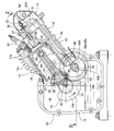
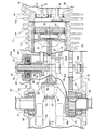
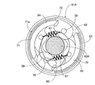
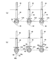
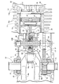
図1〜図5は本発明の第1実施例を示すものであり、図1は内燃機関の縦断側面図であって図2の1−1線に沿う断面図、図2は図1の2−2線拡大断面図、図3は動力伝達遮断状態に在る遠心クラッチの横断面図、図4は動力伝達状態にある遠心クラッチの図3に対応した断面図、図5はカムシャフトの回転に応じた吸気側タペットの作動状態を順次示す図であって(a)は低回転の状態、(b)は高回転の状態を示す図である。   1 to 5 show a first embodiment of the present invention. FIG. 1 is a longitudinal side view of an internal combustion engine, which is a cross-sectional view taken along line 1-1 of FIG. 2, and FIG. -2 is an enlarged sectional view, FIG. 3 is a transverse sectional view of the centrifugal clutch in a power transmission cut-off state, FIG. 4 is a sectional view corresponding to FIG. 3 of the centrifugal clutch in a power transmission state, and FIG. It is a figure which shows sequentially the operation state of the inhalation | air_intake side tappet according to this, (a) is a state of low rotation, (b) is a figure which shows the state of high rotation.

先ず図1および図2において、この内燃機関は、たとえば作業機等に用いられるようにして空冷の単気筒に構成されており、その機関本体11は、クランクケース12と、該クランクケース12の一側面から上向きに傾斜して突出するシリンダブロック13と、該シリンダブロック13の頭部に接合されるシリンダヘッド14と、シリンダヘッド14に結合されるヘッドカバー16とを備え、シリンダブロック13およびシリンダヘッド14の外側面には多数の空冷用フィン13a…,14a…が設けられている。   First, in FIGS. 1 and 2, the internal combustion engine is configured as an air-cooled single cylinder so as to be used in, for example, a work machine, and the engine main body 11 includes a crankcase 12 and one of the crankcases 12. The cylinder block 13 and the cylinder head 14 are provided with a cylinder block 13 projecting obliquely upward from the side surface, a cylinder head 14 joined to the head of the cylinder block 13, and a head cover 16 coupled to the cylinder head 14. Are provided with a number of air cooling fins 13a, 14a,.

クランクケース12は、シリンダブロック13と一体に鋳造成形されて一側を開放したケース本体16と、そのケース本体16の開放端に締結されるサイドカバー17とから成るものであり、オイルを貯留するクランク室18がクランクケース12内に形成される。このクランクケース12には、一対のカウンタウエイト19a,19bおよび両カウンタウエイト19a,19b間を結ぶクランクピン19cとを一体に有するクランクシャフト19が回転自在に支承される。而して前記クランクシャフト19の両端部はクランクケース12における前記ケース本体16および前記サイドカバー17を回転自在に貫通して外方に突出するものであり、クランクシャフト19およびケース本体16間には、ボールベアリング20と、該ボールベアリング20の外方に配置される環状のシール部材21とが介装され、前記クランクシャフト19および前記サイドカバー17間には、ボールベアリング22と、該ボールベアリング22の外方に配置される環状のシール部材23とが介装される。   The crankcase 12 is composed of a case main body 16 that is integrally formed with the cylinder block 13 and opened on one side, and a side cover 17 that is fastened to an open end of the case main body 16 and stores oil. A crank chamber 18 is formed in the crankcase 12. A crankshaft 19 integrally having a pair of counterweights 19a and 19b and a crankpin 19c connecting both counterweights 19a and 19b is rotatably supported on the crankcase 12. Thus, both end portions of the crankshaft 19 pass through the case main body 16 and the side cover 17 in the crankcase 12 so as to freely rotate and protrude outward, between the crankshaft 19 and the case main body 16. The ball bearing 20 and an annular seal member 21 disposed outside the ball bearing 20 are interposed, and between the crankshaft 19 and the side cover 17, a ball bearing 22 and the ball bearing 22 are interposed. And an annular seal member 23 disposed outside.

シリンダブロック13には、ピストン24を摺動自在に嵌合せしめるシリンダボア25が形成されており、ピストン24の頂部を臨ませる燃焼室26がシリンダブロック13およびシリンダヘッド14間に形成される。前記ピストン24にはコネクティングロッド27の一端がピストンピン28を介して連結され、コネクティングロッド27の他端はクランクシャフト19のクランクピン19cに連結される。すなわちコネクティングロッド27の他端には前記クランクピン19cの略半周を嵌合せしめる半円状の凹部29が設けられ、前記クランクピン19cの残余の略半周を嵌合せしめる半円状の凹部30を有するクランクキャップ31が、一対のボルト32…によってコネクティングロッド27の他端に締結される。   The cylinder block 13 is formed with a cylinder bore 25 into which the piston 24 is slidably fitted, and a combustion chamber 26 that faces the top of the piston 24 is formed between the cylinder block 13 and the cylinder head 14. One end of a connecting rod 27 is connected to the piston 24 via a piston pin 28, and the other end of the connecting rod 27 is connected to a crank pin 19 c of the crankshaft 19. That is, the other end of the connecting rod 27 is provided with a semicircular recess 29 for fitting the substantially half circumference of the crank pin 19c, and a semicircular recess 30 for fitting the remaining substantially half circumference of the crank pin 19c. A crank cap 31 is fastened to the other end of the connecting rod 27 by a pair of bolts 32.

しかもクランクキャップ31には、前記クランクシャフト19の回転に応じてクランク室18内のオイルを撥ね上げるオイルディッパ33が一体に突設されており、このオイルディッパ33は前記クランク室18に収容されることになる。   In addition, the crank cap 31 is integrally provided with an oil dipper 33 that repels oil in the crank chamber 18 in accordance with the rotation of the crankshaft 19. The oil dipper 33 is accommodated in the crank chamber 18. Become.

またシリンダヘッド14には、燃焼室26に通じ得る吸気ポート35および排気ポート36が形成されるとともに、吸気ポート35および燃焼室26間を開閉する機関弁としての吸気弁37と、排気ポート36および燃焼室26間を開閉する排気弁38とが開閉作動可能に配設され、吸気弁37は弁ばね39で閉弁方向に付勢され、排気弁38は図示しない弁ばねで閉弁方向に付勢される。さらにシリンダヘッド14には、前記燃焼室26に前端部を臨ませる点火プラグ41が取付けられる。   In addition, an intake port 35 and an exhaust port 36 that can communicate with the combustion chamber 26 are formed in the cylinder head 14, and an intake valve 37 as an engine valve that opens and closes between the intake port 35 and the combustion chamber 26, an exhaust port 36, and An exhaust valve 38 that opens and closes between the combustion chambers 26 is disposed so as to be able to open and close. The intake valve 37 is urged in a valve closing direction by a valve spring 39, and the exhaust valve 38 is urged in a valve closing direction by a valve spring (not shown). Be forced. Further, a spark plug 41 is attached to the cylinder head 14 so that the front end portion faces the combustion chamber 26.

吸気弁37および排気弁38を開閉駆動する動弁装置42Aは、前記クランクケース12で回転自在に支承されるカムシャフト43Aと、該カムシャフト43Aの回転に応じて上下に摺動するようにしてクランクケース13のケース本体16およびシリンダブロック13に支承される吸気側タペット46と、前記カムシャフト43Aの回転に応じて上下に摺動するようにして前記ケース本体16およびシリンダブロック13に支承される排気側タペット47と、前記吸気側タペット46の上端部に下端部を連設させて上下に延びる吸気側プッシュロッド48と、前記排気側タペット47の上端部に下端部を連設させて上下に延びる排気側プッシュロッド(図示せず)と、クランクシャフト19と平行な軸線を有してシリンダヘッド14に設けられるロッカシャフト50で揺動自在に支承される吸気側ロッカアーム51と、前記ロッカシャフト52で揺動自在に支承される排気側ロッカアーム(図示せず)とを備え、吸気側ロッカアーム51の一端部は前記吸気側プッシュロッド48の上端に当接され、排気側ロッカアームの一端部は前記排気側プッシュロッドの上端に当接され、吸気側ロッカアーム51および排気側ロッカアームの他端部には、吸気弁37および排気弁38の頭部に当接されるタペットねじ53…が進退位置を調節可能として螺合される。   A valve gear 42A that opens and closes the intake valve 37 and the exhaust valve 38 is configured to slide up and down according to the rotation of the camshaft 43A and the camshaft 43A that is rotatably supported by the crankcase 12. The intake side tappet 46 supported by the case main body 16 and the cylinder block 13 of the crankcase 13 and the case main body 16 and the cylinder block 13 are slid up and down according to the rotation of the camshaft 43A. An exhaust-side tappet 47, an intake-side pushrod 48 that extends vertically by connecting the lower end to the upper end of the intake-side tappet 46, and a lower-end portion that extends vertically from the upper end of the exhaust-side tappet 47 An exhaust-side push rod (not shown) that extends and an axis parallel to the crankshaft 19 are provided on the cylinder head 14. An intake-side rocker arm 51 that is swingably supported by the rocker shaft 50, and an exhaust-side rocker arm (not shown) that is swingably supported by the rocker shaft 52. One end of the intake-side rocker arm 51 is One end of the exhaust side rocker arm is in contact with the upper end of the intake side push rod 48, and the upper end of the exhaust side push rod is in contact with the other end of the intake side rocker arm 51 and the exhaust side rocker arm. The tappet screws 53 that are in contact with the head of the exhaust valve 38 are screwed together so that the advance / retreat position can be adjusted.

前記カムシャフト43Aの両端部は、前記クランクケース13におけるケース本体16およびサイドカバー17で回転自在に支承されており、このカムシャフト43Aおよび前記クランクシャフト19間には、クランクシャフト19に固定される駆動ギヤ55と、該駆動ギヤ55に噛合するようにして前記カムシャフト43Aに固定される被動ギヤ56とで構成される調時伝動機構57が設けられ、この調時伝動機構57によって前記クランクシャフト19の回転動力が1/2の減速比で前記カムシャフト43Aに伝達される。   Both end portions of the camshaft 43A are rotatably supported by the case body 16 and the side cover 17 in the crankcase 13, and the camshaft 43A and the crankshaft 19 are fixed to the crankshaft 19 between them. A timing transmission mechanism 57 is provided that includes a drive gear 55 and a driven gear 56 that is fixed to the camshaft 43A so as to mesh with the drive gear 55. The timing transmission mechanism 57 causes the crankshaft to rotate. 19 rotational power is transmitted to the camshaft 43A at a reduction ratio of 1/2.

前記カムシャフト43Aには、前記排気側タペット47の下端部を摺接させるようにして排気側カム58が一体に設けられる。また前記カムシャフト43Aには、吸気側低速用カム59が一体に設けられるとともに、吸気側高速用カム60が前記吸気側低速用カム59に隣接した位置で相対回転可能に支承されており、カム従動部材である吸気側タペット46が、前記吸気側低速用カム59および前記吸気側高速用カム60にともに接触することを可能とするとともに前記吸気側低速用カム59および前記吸気側高速用カム60のいずれかに従動して作動することを可能として、機関本体11におけるクランクケース13のケース本体16およびシリンダブロック13に支承されている。   An exhaust side cam 58 is integrally provided on the camshaft 43A so that the lower end portion of the exhaust side tappet 47 is in sliding contact. An intake side low speed cam 59 is integrally provided on the cam shaft 43A, and an intake side high speed cam 60 is supported so as to be relatively rotatable at a position adjacent to the intake side low speed cam 59. The intake side tappet 46, which is a driven member, can contact both the intake side low speed cam 59 and the intake side high speed cam 60, and the intake side low speed cam 59 and the intake side high speed cam 60. The engine body 11 is supported by the case body 16 of the crankcase 13 and the cylinder block 13 so as to be able to operate.

吸気側低速用カム59は、カムシャフト43Aの軸線を中心とする円弧状のベース円部59aと、該ベース円部59aから外側方に突出する高位部59bとを有してカムシャフト43Aに一体に設けられており、吸気側高速用カム60は、前記低速用カム59のベース円部59aと同一半径のベース円部60aを有するとともに前記低速用カム59の高位部59bより突出量を大きくして前記ベース円部60aから突出する高位部60bを有するものである。   The intake-side low-speed cam 59 has an arc-shaped base circle portion 59a centering on the axis of the camshaft 43A and a high-order portion 59b that protrudes outward from the base circle portion 59a, and is integrated with the camshaft 43A. The intake-side high-speed cam 60 has a base circle portion 60a having the same radius as the base circle portion 59a of the low-speed cam 59 and has a larger protruding amount than the high-order portion 59b of the low-speed cam 59. And a high-order part 60b protruding from the base circle part 60a.

前記吸気側高速用カム60と、前記吸気側低速用カム59が一体に設けられたカムシャフト43Aとの間には、該カムシャフト43Aの回転数が所定回転数以上となったときに前記吸気側高速用カム60を前記吸気側低速用カム59に位相を合わせつつ前記カムシャフト43Aに連結する遠心クラッチ61Aが、カムシャフト43Aと同軸にして設けられる。   Between the intake-side high-speed cam 60 and the camshaft 43A integrally provided with the intake-side low-speed cam 59, when the rotational speed of the camshaft 43A becomes a predetermined rotational speed or more, the intake air A centrifugal clutch 61A that connects the side high speed cam 60 to the camshaft 43A in phase with the intake side low speed cam 59 is provided coaxially with the camshaft 43A.

図3において、遠心クラッチ61Aは、円盤状のドライブプレート62と、該ドライブプレート62を同軸に覆う椀状のクラッチハウジング63と、前記ドライブプレート62の回転に伴う遠心力の作用に応じて前記クラッチハウジング63の内周の周方向に等間隔をあけた複数箇所たとえば2箇所に摩擦係合し得るようにしてドライブプレート62に回動可能に軸支されるクラッチウエイト64,65と、これらのクラッチウエイト64,65を前記ドライブプレート62との間に挟むリング状のサイドプレート66(図2参照)と、前記クラッチハウジング63の内周との摩擦係合を解除する側に前記クラッチウエイト64,65を付勢するばね力を発揮するようにしてクラッチハウジング63の周方向に隣接するクラッチウエイト64,65間にそれぞれ設けられるクラッチばね67,67とを備える。   In FIG. 3, the centrifugal clutch 61 </ b> A includes a disk-shaped drive plate 62, a hook-shaped clutch housing 63 that coaxially covers the drive plate 62, and the clutch according to the action of centrifugal force accompanying the rotation of the drive plate 62. Clutch weights 64 and 65 pivotally supported by the drive plate 62 so as to be able to frictionally engage at a plurality of, for example, two places at equal intervals in the circumferential direction of the inner circumference of the housing 63, and these clutches The clutch weights 64, 65 are disposed on the side where the frictional engagement between the ring-shaped side plate 66 (see FIG. 2) sandwiching the weights 64, 65 between the drive plate 62 and the inner periphery of the clutch housing 63 is released. The clutch weight 64 adjacent to the circumferential direction of the clutch housing 63 so as to exert a spring force for urging the clutch housing 63 Each comprise a clutch spring 67 provided between 65.

前記カムシャフト43Aには、図2で示すように、該カムシャフト43Aを同軸に囲繞する円筒状の筒部材68が固定されており、前記ドライブプレート62は該筒部材68に固定される。また前記吸気側高速用カム60には、前記カムシャフト43Aを同軸に囲繞する円筒状の連結筒69の一端が同軸にかつ一体に連設されており、該連結筒69の他端に前記クラッチハウジング63が同軸にかつ一体に連設される。すなわちドライブプレート62は前記カムシャフトとともに回転し、前記クラッチハウジング63は前記吸気側高速用カム60とともに回転することになる。   As shown in FIG. 2, a cylindrical cylindrical member 68 that coaxially surrounds the camshaft 43 </ b> A is fixed to the camshaft 43 </ b> A, and the drive plate 62 is fixed to the cylindrical member 68. One end of a cylindrical connecting cylinder 69 that coaxially surrounds the camshaft 43A is coaxially and integrally connected to the intake side high-speed cam 60, and the other end of the connecting cylinder 69 is connected to the clutch. The housing 63 is coaxially and integrally connected. That is, the drive plate 62 rotates with the camshaft, and the clutch housing 63 rotates with the intake side high speed cam 60.

前記クラッチウエイト64,65の一端部は支軸70,70を介してドライブプレート62に回動可能に軸支されるものであり、このクラッチウエイト64,65には、クラッチハウジング63の内周に摩擦係合し得る摩擦材71,72が貼着される。しかも前記クラッチハウジング63の内周の1個所には係止凹部73が設けられており、前記両クラッチウエイト64,65の一方64の摩擦材71には、前記係止凹部73に係合し得る係合突部71aが突設される。   One end portions of the clutch weights 64 and 65 are pivotally supported on the drive plate 62 via support shafts 70 and 70, and the clutch weights 64 and 65 are provided on the inner periphery of the clutch housing 63. Friction materials 71 and 72 that can be frictionally engaged are attached. In addition, a locking recess 73 is provided at one location on the inner periphery of the clutch housing 63, and the friction material 71 of one of the clutch weights 64 and 65 can be engaged with the locking recess 73. An engaging protrusion 71a is provided.

このような遠心クラッチ61Aでは、カムシャフト43Aの回転数が低い状態では、クラッチウエイト64,65に作用する遠心力がクラッチばね67…のばね力よりも小さく、クラッチウエイト64,65の回動位置は、図3で示すように、摩擦材71,72をクラッチハウジング63の内周に摩擦係合させる位置とはなっていない。而してカムシャフト43Aの回転数が所定回転数以上になると、クラッチウエイト64,65に作用する遠心力がクラッチばね67…のばね力よりも大きくなり、クラッチウエイト64,65は摩擦材71,72をクラッチハウジング63の内周に摩擦係合させる位置に回動する。この際、クラッチウエイト64の摩擦材71には係合突部71aが突設されており、この係合突部71aがクラッチハウジング63の内周に当接した状態では、摩擦材71,72の全面がクラッチハウジング63の内周に当接していないので、クラッチハウジング63に対してドライブプレート62が相対回動することになり、前記係合突部71aが、図4で示すように、クラッチハウジング63の係止凹部73に係合することによって摩擦材71,72の全面がクラッチハウジング63の内周に圧接されて摩擦係合し、それによりドライブプレート62すなわちカムシャフト43Aと、クラッチハウジング63すなわち吸気側高速用カム60とが連結されて一体的に回転することになる。   In such a centrifugal clutch 61A, when the rotational speed of the camshaft 43A is low, the centrifugal force acting on the clutch weights 64, 65 is smaller than the spring force of the clutch springs 67, and the rotational positions of the clutch weights 64, 65 As shown in FIG. 3, the friction members 71 and 72 are not positioned to be frictionally engaged with the inner periphery of the clutch housing 63. Thus, when the rotational speed of the camshaft 43A exceeds a predetermined rotational speed, the centrifugal force acting on the clutch weights 64, 65 becomes larger than the spring force of the clutch springs 67, and the clutch weights 64, 65 72 is rotated to a position for frictional engagement with the inner periphery of the clutch housing 63. At this time, an engagement projection 71 a is provided on the friction material 71 of the clutch weight 64, and when the engagement projection 71 a is in contact with the inner periphery of the clutch housing 63, the friction materials 71 and 72. Since the entire surface is not in contact with the inner periphery of the clutch housing 63, the drive plate 62 is rotated relative to the clutch housing 63, and the engagement protrusion 71a is, as shown in FIG. 63, the friction members 71 and 72 are brought into pressure contact with the inner periphery of the clutch housing 63 to be frictionally engaged, whereby the drive plate 62, that is, the camshaft 43A, and the clutch housing 63, that is, The intake-side high-speed cam 60 is connected to rotate integrally.

しかも前記係止凹部73に前記係合突部71aが係合した状態では、前記カムシャフト43Aおよび前記連結筒69の相対位置、すなわちカムシャフト43Aに一体に設けられる吸気側低速用カム59ならびに前記連結筒69に結合される吸気側高速用カム60の相対位置は、吸気側高速用カム59の高位部59bおよび吸気側高速用カム60bの位相を一致させる相対位置となる。   In addition, in a state where the engaging protrusion 71a is engaged with the locking recess 73, the relative position between the camshaft 43A and the connecting cylinder 69, that is, the intake-side low-speed cam 59 provided integrally with the camshaft 43A and the above-mentioned The relative position of the intake side high speed cam 60 coupled to the connecting cylinder 69 is a relative position where the phases of the high position portion 59b of the intake side high speed cam 59 and the intake side high speed cam 60b are matched.

次にこの第1実施例の作用について説明すると、カムシャフト43Aには、吸気側低速用カム59が固設されるとともに、吸気側低速用カム59のベース円部59aと同一半径のベース円部60aを有するとともに前記吸気側低速用カム59の高位部59bより突出量を大きくした高位部60bを有する吸気側高速用カム60が前記吸気側低速用カム59に隣接した位置で相対回転可能に支承され、吸気側タペット46が、吸気側低速用カム59および吸気側高速用カム60にともに接触することを可能とするとともに吸気側低速用カム59および吸気側高速用カム60のいずれかに従動して作動することを可能として、機関本体11におけるクランクケース13のケース本体16およびシリンダブロック13に支承され、カムシャフト43Aの回転数が所定回転数以上となったときに前記吸気側高速用カム60を前記吸気側低速用カム59に位相を合わせつつカムシャフト43Aに連結する遠心クラッチ61Aが、前記カムシャフト43Aと同軸にして前記カムシャフト43Aおよび前記吸気側高速用カム60間に設けられている。   Next, the operation of the first embodiment will be described. The intake shaft low speed cam 59 is fixed on the camshaft 43A, and the base circle portion having the same radius as the base circle portion 59a of the intake side low speed cam 59 is described. The intake-side high-speed cam 60 having a high-order portion 60b having a protrusion 60a and a protruding amount larger than the high-order portion 59b of the intake-side low-speed cam 59 is supported so as to be relatively rotatable at a position adjacent to the intake-side low-speed cam 59. Thus, the intake side tappet 46 can be in contact with both the intake side low speed cam 59 and the intake side high speed cam 60 and is driven by either the intake side low speed cam 59 or the intake side high speed cam 60. The camshaft 43 is supported by the case main body 16 and the cylinder block 13 of the crankcase 13 in the engine main body 11. A centrifugal clutch 61A that connects the intake-side high-speed cam 60 to the camshaft 43A in phase with the intake-side low-speed cam 59 when the rotational speed of the engine becomes equal to or greater than a predetermined rotational speed is coaxial with the camshaft 43A. The camshaft 43A and the intake side high-speed cam 60 are provided.

したがってカムシャフト43Aの回転数が所定回転数未満のときには、遠心クラッチ61Aは動力伝達遮断状態にあり、この状態では図5(a)で示すように、吸気側低速用カム59はカムシャフト43Aとともに回転するが、吸気側高速用カム60はカムシャフト43Aの軸線まわりに空転することになり、吸気弁37は吸気側低速用カム59のカムプロフィルに応じた作動特性で開閉作動する。   Therefore, when the rotational speed of the camshaft 43A is less than the predetermined rotational speed, the centrifugal clutch 61A is in a power transmission cut-off state, and in this state, the intake-side low-speed cam 59 is combined with the camshaft 43A as shown in FIG. Although rotating, the intake-side high-speed cam 60 idles about the axis of the camshaft 43A, and the intake valve 37 opens and closes with an operating characteristic corresponding to the cam profile of the intake-side low-speed cam 59.

一方、カムシャフト43Aの回転数が所定回転数以上に上昇したときには、遠心クラッチ61Aが、吸気側高速用カム60を吸気側低速用カム59に位相を合わせつつカムシャフト43Aに連結し、図5(b)で示すように、吸気側低速用カム59および吸気側高速用カム60が同一位相で回転することになり、吸気側高速用カム60の高位部60bは、吸気側低速用カム59の高位部59bよりも突出量が大きいので、吸気側タペット46は吸気側低速用カム59の高位部59bに接触することなく、吸気側高速用カム60の高位部60bに従動して作動することになり、吸気弁37が吸気側高速用カム60のカムプロフィルに応じた作動特性で開閉作動することになる。   On the other hand, when the rotational speed of the camshaft 43A rises above a predetermined rotational speed, the centrifugal clutch 61A connects the intake side high speed cam 60 to the camshaft 43A in phase with the intake side low speed cam 59, and FIG. As shown in (b), the intake-side low-speed cam 59 and the intake-side high-speed cam 60 rotate in the same phase, and the high position portion 60b of the intake-side high-speed cam 60 Since the protruding amount is larger than that of the high position portion 59b, the intake side tappet 46 does not come into contact with the high position portion 59b of the intake side low speed cam 59 but operates by being driven by the high position portion 60b of the intake side high speed cam 60. Thus, the intake valve 37 opens and closes with an operating characteristic corresponding to the cam profile of the intake-side high-speed cam 60.

しかも吸気弁37の作動特性を切り換えるための遠心クラッチ61Aは、カムシャフト43Aと同軸にしてカムシャフト43Aおよび吸気側高速用カム60間に設けられるので、簡単かつコンパクトな構造で吸気弁37の作動特性を変化させることができる。   Moreover, the centrifugal clutch 61A for switching the operation characteristics of the intake valve 37 is provided between the cam shaft 43A and the intake side high-speed cam 60 so as to be coaxial with the cam shaft 43A, so that the operation of the intake valve 37 can be performed with a simple and compact structure. Characteristics can be changed.

上記第1実施例では、吸気弁37および排気弁38のうち吸気弁37の作動特性のみが、カムシャフト43Aの回転数変化に応じて変化する場合について説明したが、吸気弁37および排気弁38の両方の作動特性が変化するようにした本発明の第2実施例について図6を参照しながら説明するが、上記第1実施例に対応する部分には同一の参照符号を付して図示するのみとし、詳細な説明は省略する。   In the first embodiment, the case where only the operating characteristic of the intake valve 37 of the intake valve 37 and the exhaust valve 38 changes according to the change in the rotation speed of the camshaft 43 </ b> A has been described, but the intake valve 37 and the exhaust valve 38. A second embodiment of the present invention in which both of the operating characteristics are changed will be described with reference to FIG. 6. The parts corresponding to the first embodiment are indicated by the same reference numerals. Detailed description will be omitted.

機関弁である吸気弁37および排気弁38を開閉駆動する動弁装置42Bは、クランクケース12で回転自在に支承されるとともにクランクシャフト19との間に調時伝動機構57が設けられるカムシャフト43Bと、該カムシャフト43Bの回転に応じて上下に摺動するようにしてクランクケース13のケース本体16およびシリンダブロック13に支承される吸気側タペット46と、前記カムシャフト43Bの回転に応じて上下に摺動するようにして前記ケース本体16およびシリンダブロック13に支承される排気側タペット47とを備える。   A valve operating device 42B that opens and closes an intake valve 37 and an exhaust valve 38, which are engine valves, is rotatably supported by the crankcase 12 and a camshaft 43B provided with a timing transmission mechanism 57 between the crankshaft 19 and the camshaft 43B. The intake side tappet 46 supported by the case body 16 and the cylinder block 13 of the crankcase 13 so as to slide up and down according to the rotation of the camshaft 43B, and up and down according to the rotation of the camshaft 43B. And an exhaust side tappet 47 supported by the case body 16 and the cylinder block 13.

また前記カムシャフト43Bには、吸気側低速用カム59および排気側低速用カム75が一体に設けられるとともに、吸気側高速用カム60および排気側高速用カム76が前記吸気側低速用カム59および前記排気側低速用カム75に隣接した位置で相対回転可能に支承される。しかも吸気側高速用カム60は排気側低速用カム75側で吸気側低速用カム59に隣接する位置に配置され、排気側高速用カム76は吸気側低速用カム59側で排気側低速用カム75に隣接する位置に配置される。   The camshaft 43B is integrally provided with an intake side low speed cam 59 and an exhaust side low speed cam 75, and an intake side high speed cam 60 and an exhaust side high speed cam 76 are provided with the intake side low speed cam 59 and It is supported so as to be relatively rotatable at a position adjacent to the exhaust-side low-speed cam 75. Moreover, the intake-side high-speed cam 60 is disposed on the exhaust-side low-speed cam 75 side and adjacent to the intake-side low-speed cam 59, and the exhaust-side high-speed cam 76 is on the intake-side low-speed cam 59 side. 75 is disposed at a position adjacent to 75.

カム従動部材である吸気側タペット46は、前記吸気側低速用カム59および前記吸気側高速用カム60にともに接触することを可能とするとともに前記吸気側低速用カム59および前記吸気側高速用カム60のいずれかに従動して作動することを可能として、機関本体11におけるクランクケース13のケース本体16およびシリンダブロック13に支承され、カム受動部材である排気側タペット47は、前記排気側低速用カム75および前記排気側高速用カム76にともに接触することを可能とするとともに前記排気側低速用カム75および前記排気側高速用カム76のいずれかに従動して作動することを可能として、機関本体11におけるクランクケース13のケース本体16およびシリンダブロック13に支承される。   The intake side tappet 46, which is a cam driven member, allows the intake side low speed cam 59 and the intake side high speed cam 60 to be in contact with each other, and the intake side low speed cam 59 and the intake side high speed cam 60. The exhaust side tappet 47, which is supported by the case body 16 and the cylinder block 13 of the crankcase 13 in the engine body 11 and is a cam passive member, can be operated by being driven by any one of the engine body 11. It is possible to make contact with both the cam 75 and the exhaust-side high-speed cam 76 and to operate by following either the exhaust-side low-speed cam 75 or the exhaust-side high-speed cam 76. The main body 11 is supported by the case main body 16 and the cylinder block 13 of the crankcase 13.

前記吸気側高速用カム60および前記排気側高速用カム76と、前記吸気側低速用カム59および前記排気側低速用カム75が一体に設けられたカムシャフト43Bとの間には、該カムシャフト43Bの回転数が所定回転数以上となったときに前記吸気側高速用カム60および前記排気側高速用カム76を前記吸気側低速用カム59および前記排気側低速用カム75に位相を合わせつつ前記カムシャフト43Bに連結する遠心クラッチ61Bが、カムシャフト43Bと同軸にして設けられる。   Between the intake-side high-speed cam 60 and the exhaust-side high-speed cam 76 and the intake-side low-speed cam 59 and the exhaust-side low-speed cam 75 provided integrally with the camshaft 43B. When the rotational speed of 43B becomes equal to or higher than a predetermined rotational speed, the intake side high speed cam 60 and the exhaust side high speed cam 76 are in phase with the intake side low speed cam 59 and the exhaust side low speed cam 75. A centrifugal clutch 61B connected to the camshaft 43B is provided coaxially with the camshaft 43B.

この第2実施例によれば、カムシャフト43Bの回転数が所定回転数未満のときには、遠心クラッチ61Bは動力伝達遮断状態にあり、吸気側低速用カム59および排気側低速用カム75はカムシャフト43Bとともに回転するが、吸気側高速用カム60および排気側高速用カム76はカムシャフト43Bの軸線まわりに空転することになり、吸気弁37は吸気側低速用カム59のカムプロフィルに応じた作動特性で開閉作動し、排気弁38は排気側低速用カム75のカムプロフィルに応じた作動特性で開閉作動する。   According to the second embodiment, when the rotational speed of the camshaft 43B is less than the predetermined rotational speed, the centrifugal clutch 61B is in a power transmission cut-off state, and the intake side low speed cam 59 and the exhaust side low speed cam 75 are connected to the camshaft. 43B, the intake side high speed cam 60 and the exhaust side high speed cam 76 idle around the axis of the cam shaft 43B, and the intake valve 37 operates according to the cam profile of the intake side low speed cam 59. The exhaust valve 38 opens and closes with an operating characteristic corresponding to the cam profile of the exhaust-side low-speed cam 75.

一方、カムシャフト43Bの回転数が所定回転数以上に上昇したときには、遠心クラッチ61Bが、吸気側高速用カム60を吸気側低速用カム59に位相を合わせつつカムシャフト43Bに連結し、排気側高速用カム76を排気側低速用カム75に位相を合わせつつカムシャフト43Bに連結し、吸気弁37が吸気側高速用カム60のカムプロフィルに応じた作動特性で開閉作動し、排気弁38が排気側高速用カム76のカムプロフィルに応じた作動特性で開閉作動することになる。   On the other hand, when the rotational speed of the camshaft 43B rises above a predetermined rotational speed, the centrifugal clutch 61B connects the intake side high speed cam 60 to the camshaft 43B in phase with the intake side low speed cam 59, and the exhaust side The high-speed cam 76 is connected to the camshaft 43B in phase with the exhaust-side low-speed cam 75, the intake valve 37 opens and closes with operating characteristics corresponding to the cam profile of the intake-side high-speed cam 60, and the exhaust valve 38 The opening / closing operation is performed with an operation characteristic corresponding to the cam profile of the exhaust-side high-speed cam 76.

しかも吸気弁37および排気弁38の作動特性を切り換えるための遠心クラッチ61Bは、カムシャフト43Bと同軸にしてカムシャフト43Bと吸気側高速用カム60および排気側高速用カム76との間に設けられるので、簡単かつコンパクトな構造で吸気弁37および排気弁38の作動特性を変化させることができる。   Moreover, the centrifugal clutch 61B for switching the operation characteristics of the intake valve 37 and the exhaust valve 38 is provided between the camshaft 43B, the intake-side high-speed cam 60, and the exhaust-side high-speed cam 76 so as to be coaxial with the camshaft 43B. Therefore, the operation characteristics of the intake valve 37 and the exhaust valve 38 can be changed with a simple and compact structure.

以上、本発明の実施例を説明したが、本発明は上記実施例に限定されるものではなく、特許請求の範囲に記載された本発明を逸脱することなく種々の設計変更を行うことが可能である。   Although the embodiments of the present invention have been described above, the present invention is not limited to the above-described embodiments, and various design changes can be made without departing from the present invention described in the claims. It is.

第1実施例の内燃機関の縦断側面図であって図2の1−1線に沿う断面図である。FIG. 3 is a longitudinal side view of the internal combustion engine of the first embodiment, and is a cross-sectional view taken along line 1-1 of FIG. 図1の2−2線拡大断面図である。FIG. 2 is an enlarged sectional view taken along line 2-2 of FIG. 動力伝達遮断状態に在る遠心クラッチの横断面図である。It is a cross-sectional view of the centrifugal clutch in a power transmission cut-off state. 動力伝達状態にある遠心クラッチの図3に対応した断面図である。It is sectional drawing corresponding to FIG. 3 of the centrifugal clutch in a power transmission state. カムシャフトの回転に応じた吸気側タペットの作動状態を順次示す図であって(a)は低回転の状態、(b)は高回転の状態を示す図である。It is a figure which shows sequentially the operation state of the suction side tappet according to rotation of a cam shaft, (a) is a state of low rotation, (b) is a figure which shows the state of high rotation. 第2実施例の図2に対応した内燃機関の断面図である。It is sectional drawing of the internal combustion engine corresponding to FIG. 2 of 2nd Example.

符号の説明Explanation of symbols

11・・・機関本体
37・・・機関弁である吸気弁
38・・・機関弁である排気弁
43A,43B・・・カムシャフト
46・・・カム従動部材である吸気側タペット
47・・・カム従動部材である排気側タペット
59・・・吸気側低速用カム
59a,60a・・・ベース円部
59b,60b・・・高位部
60・・・吸気側高速用カム
61A,61B・・・遠心クラッチ
75・・・排気側低速用カム
76・・・排気側高速用カム
DESCRIPTION OF SYMBOLS 11 ... Engine main body 37 ... Intake valve 38 which is an engine valve ... Exhaust valves 43A, 43B which are engine valves ... Cam shaft 46 ... Intake side tappet 47 which is a cam driven member Exhaust side tappet 59 which is a cam follower member ... Intake side low speed cam 59a, 60a ... Base circular part 59b, 60b ... High position part 60 ... Intake side high speed cam 61A, 61B ... Centrifugal Clutch 75... Exhaust side low speed cam 76... Exhaust side high speed cam

Claims (1)

機関本体(11)に開閉作動可能に配設されるととも閉弁側に付勢される機関弁(37,38)と、前記機関本体(11)に回転自在に支承されるカムシャフト(43A,43B)と、該カムシャフト(43A,43B)とともに回転するカム(59,60;75,76)に従動して前記機関弁(37,38)側に開弁力を伝達するように作動するカム従動部材(46,47)とを備え、前記機関弁(37,38)の作動特性を前記カムシャフト(43A,43B)の回転数変化に応じて変化させ得る内燃機関の可変動弁装置において、前記カムシャフト(43A,43B)の軸線を中心とする円弧状のベース円部(59a)と、該ベース円部(59a)から外側方に突出する高位部(59b)とを有する低速用カム(59,75)が固設される前記カムシャフト(43A,43B)に、前記低速用カム(59,75)のベース円部(59a)と同一半径のベース円部(60a)を有するとともに前記低速用カム(59,75)の高位部(59b)より突出量を大きくした高位部(60b)を有する高速用カム(60,76)が、前記低速用カム(59,75)に隣接した位置で相対回転可能に支承され、前記低速用カム(59,75)および前記高速用カム(60,76)にともに接触し得る前記カム従動部材(46,47)が、前記低速用カム(59,75)および前記高速用カム(60,76)のいずれかに従動して作動することを可能として機関本体(11)に支承され、前記カムシャフト(43A,43B)の回転数が所定回転数以上となったときに前記高速用カム(60,76)を前記低速用カム(59,75)に位相を合わせつつ前記カムシャフト(43A,43B)に連結する遠心クラッチ(61A,61B)が、前記カムシャフト(43A,43B)と同軸にして前記カムシャフト(43A,43B)および前記高速用カム(60,76)間に設けられることを特徴とする内燃機関の可変動弁装置。   An engine valve (37, 38) that is disposed on the engine body (11) so as to be openable / closable and is biased toward the valve closing side, and a camshaft (43A) rotatably supported by the engine body (11) , 43B) and a cam (59, 60; 75, 76) that rotates with the cam shaft (43A, 43B), and operates to transmit a valve opening force to the engine valve (37, 38) side. In a variable valve operating apparatus for an internal combustion engine, comprising a cam driven member (46, 47) and capable of changing an operating characteristic of the engine valve (37, 38) in accordance with a change in the rotational speed of the cam shaft (43A, 43B). A low-speed cam having an arc-shaped base circle part (59a) centering on the axis of the camshaft (43A, 43B) and a high-order part (59b) projecting outward from the base circle part (59a) (59,75) is fixed The cam shaft (43A, 43B) has a base circle portion (60a) having the same radius as the base circle portion (59a) of the low speed cam (59, 75) and the low speed cam (59, 75). A high speed cam (60, 76) having a high position portion (60b) having a larger protruding amount than the high position portion (59b) is supported at a position adjacent to the low speed cam (59, 75) so as to be relatively rotatable. The cam follower members (46, 47) capable of contacting both the low speed cam (59, 75) and the high speed cam (60, 76) are the low speed cam (59, 75) and the high speed cam (60). , 76) and is supported by the engine body (11) so that it can be operated and the cam for high speed when the rotational speed of the camshaft (43A, 43B) exceeds a predetermined rotational speed. (6 , 76) is connected to the camshaft (43A, 43B) in phase with the low speed cam (59, 75), and the centrifugal clutch (61A, 61B) is coaxial with the camshaft (43A, 43B). A variable valve operating apparatus for an internal combustion engine, which is provided between the cam shaft (43A, 43B) and the high speed cam (60, 76).
JP2008206287A 2008-08-08 2008-08-08 Variable valve operating device for internal combustion engine Expired - Fee Related JP5210086B2 (en)

Priority Applications (1)

Application Number Priority Date Filing Date Title
JP2008206287A JP5210086B2 (en) 2008-08-08 2008-08-08 Variable valve operating device for internal combustion engine

Applications Claiming Priority (1)

Application Number Priority Date Filing Date Title
JP2008206287A JP5210086B2 (en) 2008-08-08 2008-08-08 Variable valve operating device for internal combustion engine

Publications (2)

Publication Number Publication Date
JP2010043554A true JP2010043554A (en) 2010-02-25
JP5210086B2 JP5210086B2 (en) 2013-06-12

Family

ID=42015116

Family Applications (1)

Application Number Title Priority Date Filing Date
JP2008206287A Expired - Fee Related JP5210086B2 (en) 2008-08-08 2008-08-08 Variable valve operating device for internal combustion engine

Country Status (1)

Country Link
JP (1) JP5210086B2 (en)

Citations (5)

* Cited by examiner, † Cited by third party
Publication number Priority date Publication date Assignee Title
JPS60228712A (en) * 1984-04-25 1985-11-14 Suzuki Motor Co Ltd Valve operating device for four-cycle engine
JPS62131907A (en) * 1985-12-04 1987-06-15 Mazda Motor Corp Valve drive device for engine
JPH01138309A (en) * 1987-11-24 1989-05-31 Mazda Motor Corp Valve system of engine
JPH02135608U (en) * 1989-04-12 1990-11-13
JP2002081303A (en) * 2000-09-07 2002-03-22 Suzuki Motor Corp Valve driving device for engine

Patent Citations (5)

* Cited by examiner, † Cited by third party
Publication number Priority date Publication date Assignee Title
JPS60228712A (en) * 1984-04-25 1985-11-14 Suzuki Motor Co Ltd Valve operating device for four-cycle engine
JPS62131907A (en) * 1985-12-04 1987-06-15 Mazda Motor Corp Valve drive device for engine
JPH01138309A (en) * 1987-11-24 1989-05-31 Mazda Motor Corp Valve system of engine
JPH02135608U (en) * 1989-04-12 1990-11-13
JP2002081303A (en) * 2000-09-07 2002-03-22 Suzuki Motor Corp Valve driving device for engine

Also Published As

Publication number Publication date
JP5210086B2 (en) 2013-06-12

Similar Documents

Publication Publication Date Title
TW576891B (en) Variable stroke engine
JP4057976B2 (en) Variable compression ratio engine
JP5014181B2 (en) Engine decompression device
US6843212B2 (en) Engine with variable compression ratio
ZA200601478B (en) Engine decompression system
RU2500897C2 (en) Driving device of controlled valves for internal combustion engine
WO2011030457A1 (en) Variable valve gear for internal combustion engine
JP2009281242A (en) Link type variable stroke engine
KR20120045056A (en) Valve gear of internal combustion engine
JP2009092036A (en) Stroke variable engine
EP1557542B1 (en) Engine with spring loaded compression release device
US6941900B1 (en) VAL rotary engine
JP2009092037A (en) Stroke variable engine
JP5210086B2 (en) Variable valve operating device for internal combustion engine
JP5826096B2 (en) Variable valve mechanism for internal combustion engine
WO2021165993A1 (en) A power unit with variable valve timing system
TWI393818B (en) Valve operating system for internal combustion engine
JP2022520881A (en) Internal combustion engine
JP2003314237A (en) Engine
TW201728842A (en) Engine unit
CN107575273B (en) Variable valve mechanism, engine, and motorcycle
JP2010019113A (en) Device equipped with damper
JP3923314B2 (en) SOHC type valve gear for internal combustion engine
JP2015232300A (en) Internal combustion engine variable valve gear
JP4285647B2 (en) Engine cam phase variable device

Legal Events

Date Code Title Description
A621 Written request for application examination

Free format text: JAPANESE INTERMEDIATE CODE: A621

Effective date: 20101126

A977 Report on retrieval

Free format text: JAPANESE INTERMEDIATE CODE: A971007

Effective date: 20120228

A131 Notification of reasons for refusal

Free format text: JAPANESE INTERMEDIATE CODE: A131

Effective date: 20120307

A521 Written amendment

Free format text: JAPANESE INTERMEDIATE CODE: A523

Effective date: 20120507

A131 Notification of reasons for refusal

Free format text: JAPANESE INTERMEDIATE CODE: A131

Effective date: 20121205

A521 Written amendment

Free format text: JAPANESE INTERMEDIATE CODE: A523

Effective date: 20130128

TRDD Decision of grant or rejection written
A01 Written decision to grant a patent or to grant a registration (utility model)

Free format text: JAPANESE INTERMEDIATE CODE: A01

Effective date: 20130213

A61 First payment of annual fees (during grant procedure)

Free format text: JAPANESE INTERMEDIATE CODE: A61

Effective date: 20130222

FPAY Renewal fee payment (event date is renewal date of database)

Free format text: PAYMENT UNTIL: 20160301

Year of fee payment: 3

R150 Certificate of patent or registration of utility model

Free format text: JAPANESE INTERMEDIATE CODE: R150

LAPS Cancellation because of no payment of annual fees