JP2010042167A - Game machine - Google Patents
Game machine Download PDFInfo
- Publication number
- JP2010042167A JP2010042167A JP2008209052A JP2008209052A JP2010042167A JP 2010042167 A JP2010042167 A JP 2010042167A JP 2008209052 A JP2008209052 A JP 2008209052A JP 2008209052 A JP2008209052 A JP 2008209052A JP 2010042167 A JP2010042167 A JP 2010042167A
- Authority
- JP
- Japan
- Prior art keywords
- main cpu
- game
- winning combination
- command
- vibration
- Prior art date
- Legal status (The legal status is an assumption and is not a legal conclusion. Google has not performed a legal analysis and makes no representation as to the accuracy of the status listed.)
- Granted
Links
Images


Abstract
Description
本発明は、パチスロ等の遊技機に関する。 The present invention relates to a gaming machine such as a pachislot machine.
従来、複数の図柄がそれぞれの表面に配された複数のリールと、遊技メダルやコイン等(以下、「メダル等」という)が投入され、遊技者によりスタートレバーが操作されたことを検出し、複数のリールの回転の開始を要求するスタートスイッチと、複数のリールのそれぞれに対応して設けられたストップボタンが遊技者により押されたことを検出し、該当するリールの回転の停止を要求する信号を出力するストップスイッチと、複数のリールのそれぞれに対応して設けられ、それぞれの駆動力を各リールに伝達するステッピングモータと、スタートスイッチ及びストップスイッチにより出力された信号に基づいて、ステッピングモータの動作を制御し、各リールの回転及びその停止を行うリール制御部と、を備え、スタートレバーが操作されたことを検出すると、乱数値に基づいて抽籤を行い、この抽籤の結果(以下、「内部当籤役」という)とストップボタンが操作されたことを検出したタイミングとに基づいてリールの回転の停止を行う、パチスロと呼ばれる遊技機が知られている。 Conventionally, it is detected that a plurality of reels having a plurality of symbols arranged on each surface, a game medal, a coin, etc. (hereinafter referred to as a “medal, etc.”) and a start lever is operated by a player, A start switch that requests the start of rotation of a plurality of reels and a stop button provided corresponding to each of the plurality of reels are detected by the player, and the stop of rotation of the corresponding reel is requested. A stop switch that outputs a signal, a stepping motor that is provided corresponding to each of the plurality of reels, and that transmits each driving force to each reel, and a stepping motor based on the signals output by the start switch and the stop switch A reel control unit that controls the operation of each reel and rotates and stops each reel, and the start lever is operated. Is detected, the lottery is performed based on the random number value, and the reel rotation is stopped based on the result of the lottery (hereinafter referred to as “internal winning combination”) and the timing at which the stop button is detected. A game machine called pachislot is known.
このような遊技機では、スタートレバーを振動させるものが知られている(例えば、特許文献1、2参照)。この遊技機によれば、遊技状況に応じてスタートレバーを振動させる演出を行うことができる。
しかしながら、スタートレバーを振動させることにより、演出を多様化できるものの、演出によるスタートレバーの振動によってスタートレバーの操作が検知されてしまい、誤って遊技開始の処理が行われてしまう等の誤作動の問題があった。 However, although the effects can be diversified by vibrating the start lever, the operation of the start lever is detected by the start lever vibration due to the effect, and the malfunction of the game start process is erroneously performed. There was a problem.
本発明の目的は、演出としてスタートレバーを振動させることによって遊技の興趣の向上を図りながら、誤ってスタートレバーの操作が検知されることによる誤作動をなくす遊技機を提供することである。 An object of the present invention is to provide a gaming machine that eliminates malfunction caused by erroneously detecting an operation of the start lever while improving the fun of the game by vibrating the start lever as an effect.
本発明は、以下のような遊技機を提供する。 The present invention provides the following gaming machines.
(1) 複数種類の図柄を表示する表示部(例えば、後述のリール3L,3C,3R等)を複数有する図柄表示手段(例えば、後述のリール3L,3C,3R、後述の表示窓21L,21C,21R等)と、遊技者が操作可能なスタートレバー(例えば、後述のスタートレバー6等)と、前記スタートレバーの操作に応じて、単位遊技(例えば、後述の1回の遊技等)の開始を指令する遊技開始指令信号を出力する遊技開始指令手段(例えば、後述のスタートスイッチ6S等)と、所定条件の成立(例えば、後述のウェイト時間の消化処理(ウェイト処理)が終了したこと)により、前記図柄表示手段により表示される図柄の変動の開始を許可する変動開始許可手段(例えば、後述のメインCPU31等)と、前記遊技開始指令手段により遊技開始指令信号を出力されること及び前記変動開始許可手段により変動の開始が許可されることを条件に、前記図柄表示手段により表示される図柄の変動を開始させる制御を行う図柄変動開始制御手段(例えば、後述のメインCPU31等)と、前記スタートレバーを振動させる振動装置(例えば、後述の振動モータ610等)と、前記変動開始許可手段により変動の開始が許可されていないことを条件に、前記振動装置を駆動させる制御を行う振動装置制御手段(例えば、後述のサブCPU81等)と、を備えることを特徴とする遊技機。
(1) Symbol display means (for example,
(1)記載の遊技機によれば、振動装置制御手段は、変動開始許可手段により図柄の変動の開始が許可されていないことを条件に、スタートレバーを振動させる振動装置を駆動させる制御を行う。このことにより、振動装置を制御することによるスタートレバーの振動によって図柄の変動が開始されることはないので、振動装置によるスタートレバーの振動によって図柄の変動が開始されるという誤作動をなくすとともに、演出の多様化を図り遊技の興趣の向上を図ることができる。 According to the gaming machine described in (1), the vibration device control means performs control to drive the vibration device that vibrates the start lever on the condition that the start of symbol variation is not permitted by the variation start permission means. . As a result, the variation of the symbol is not started by the vibration of the start lever by controlling the vibration device, so that the malfunction that the variation of the symbol is started by the vibration of the start lever by the vibration device is eliminated. Diversify the production and improve the fun of the game.
(2) (1)記載の遊技機において、時間を計測する時間計測手段(例えば、後述のウェイト時間の消化処理(ウェイト処理)を行う手段)を更に備え、前記変動開始許可手段は、前記時間計測手段によって所定の時間(例えば、後述の前回の遊技におけるリール回転が開始してから4.1秒)が計測されたことを条件に、前記図柄表示手段により表示される図柄の変動の開始を許可することを特徴とする遊技機。 (2) In the gaming machine described in (1), the game machine further includes time measuring means (for example, means for performing wait time digestion processing (wait processing) described later), and the variation start permission means includes the time On the condition that a predetermined time (for example, 4.1 seconds from the start of reel rotation in the previous game described later) is measured by the measuring means, the start of the variation of the symbols displayed by the symbol displaying means is started. A gaming machine characterized by permission.
(2)記載の遊技機によれば、変動開始許可手段は、所定の時間が計測されたことを条件に、図柄の変動の開始を許可する。したがって、所定の時間が経過までの間に限り、振動装置によるスタートレバーの振動が行われるので、遊技者は、振動装置による振動を確認しようとしてスタートレバーの操作間隔を短くすることになる。よって、遊技機の稼働率の向上に貢献することができる。 According to the gaming machine described in (2), the change start permission means permits the start of the symbol change on the condition that the predetermined time has been measured. Therefore, since the start lever is vibrated by the vibration device only until the predetermined time elapses, the player shortens the operation interval of the start lever in an attempt to confirm the vibration by the vibration device. Therefore, it can contribute to the improvement of the operating rate of the gaming machine.
(3) (1)又は(2)に記載の遊技機において、前記遊技開始指令信号に応じて、予め定められた複数の役から当籤役を決定する内部当籤役決定手段(例えば、後述の図35の処理を行う手段、後述のメインCPU31等)と、前記内部当籤役決定手段によって決定された内部当籤役に基づいて、複数種類の振動態様の中から一の振動態様を決定する振動態様決定手段(例えば、後述のS394の処理を行う手段、後述のサブCPU81等)と、を更に備え、前記振動装置制御手段は、前記振動態様決定手段によって決定された振動態様に基づいて、前記振動装置を振動させる制御を行うことを特徴とする遊技機。
(3) In the gaming machine described in (1) or (2), an internal winning combination determining means for determining a winning combination from a plurality of predetermined combinations in accordance with the game start command signal (for example, a diagram to be described later) Vibration mode determination for determining one vibration mode from a plurality of types of vibration modes based on the means for performing the
(3)記載の遊技機によれば、振動態様によって内部当籤役を報知するので、演出の多様化を図ると共に、遊技者は、振動装置による内部当籤役の報知を確認しようとしてスタートレバーの操作間隔を短くすることになり、遊技の興趣の向上を図ることができる。 According to the gaming machine described in (3), since the internal winning combination is notified according to the vibration mode, it is possible to diversify the production, and the player operates the start lever in order to confirm the notification of the internal winning combination by the vibration device. The interval will be shortened, and the interest of the game can be improved.
本発明の遊技機によれば、演出としてスタートレバーを振動させることによって遊技の興趣の向上を図りながら、誤ってスタートレバーの操作が検知されることによる誤作動をなくすことができる。 According to the gaming machine of the present invention, it is possible to eliminate malfunction caused by erroneously detecting the operation of the start lever while improving the interest of the game by vibrating the start lever as an effect.
[パチスロの機能フロー]
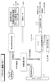
本発明の遊技機に係る実施の形態について、以下図面を参照しながら説明する。はじめに、図1を参照して、本実施の形態における遊技機(以下、パチスロ)1の機能フローについて説明する。
[Functional flow of pachislot]
Embodiments according to the gaming machine of the present invention will be described below with reference to the drawings. First, with reference to FIG. 1, the functional flow of the gaming machine (hereinafter, pachislot) 1 in the present embodiment will be described.
遊技者によりメダルが投入され、スタートレバー6が操作されると、予め定められた数値の範囲(例えば、0〜65535)の乱数から1つの値(以下、乱数値)が抽出される。
When a medal is inserted by the player and the
内部抽籤手段(後述のメインCPU31)は、抽出された乱数値に基づいて抽籤を行い、内部当籤役を決定する。内部当籤役の決定により、後述の入賞判定ラインに沿って表示を行うことを許可する図柄の組合せが決定される。尚、図柄の組合せの種別としては、メダルの払い出し、再遊技の作動、ボーナスの作動等といった特典が遊技者に与えられる「入賞」に係るものと、それ以外のいわゆる「ハズレ」に係るものとが設けられている。
The internal lottery means (
続いて、複数のリール3L,3C,3Rの回転が行われた後で、遊技者によりストップボタン7L,7C,7Rが押されると、リール停止制御手段(後述のモータ駆動回路39、後述のステッピングモータ49L,49C,49R)は、内部当籤役とストップボタンが押されたタイミングとに基づいて、該当するリールの回転を停止する制御を行う。
Subsequently, after the plurality of
ここで、パチスロ1では、基本的に、ストップボタンが押されたときから規定時間(190msec)内に、該当するリールの回転を停止する制御が行われる。本実施の形態では、上記規定時間内でのリール3L,3C,3Rの回転に伴って移動する図柄の数を「滑り駒数」と呼び、その最大数を図柄4個分に定める。
Here, in the pachi-
リール停止制御手段は、入賞に係る図柄の組合せの表示を許可する内部当籤役が決定されているときでは、上記規定時間を利用して、その図柄の組合せが入賞判定ラインに沿って極力表示されるようにリール3L,3C,3Rの回転を停止する。その一方で、内部当籤役によってその表示が許可されていない図柄の組合せについては、上記規定時間を利用して、入賞判定ラインに沿って表示されることがないようにリール3L,3C,3Rの回転を停止する。
The reel stop control means displays the symbol combination as much as possible along the winning determination line using the specified time when an internal winning combination permitting display of the symbol combination related to winning is determined. Then, the rotation of the
こうして、複数のリール3L,3C,3Rの回転が全て停止されると、入賞判定手段(後述のメインCPU31)は、入賞判定ラインに沿って表示された図柄の組合せが、入賞に係るものであるか否かの判定を行う。入賞に係るものであるとの判定が行われると、メダルの払い出し等の特典が遊技者に与えられる。以上のような一連の流れがパチスロ1における1回の遊技として行われる。
Thus, when all the rotations of the
また、パチスロ1では、前述した一連の流れの中で、液晶表示装置5により行う映像の表示、ランプ14により行う光の出力、スピーカ9L,9Rにより行う音の出力、或いはこれらの組合せを利用して様々な演出が行われる。
Further, in the
遊技者によりスタートレバー6が操作されると、前述の内部当籤役の決定に用いられた乱数値とは別に、演出用の乱数値(以下、演出用乱数値)が抽出される。演出用乱数値が抽出されると、演出内容決定手段(後述のサブCPU81)は、内部当籤役に対応づけられた複数種類の演出内容の中から今回実行するものを抽籤により決定する。
When the
演出内容が決定されると、演出実行手段(後述の液晶表示装置5、後述のスピーカ9L,9R、後述のランプ14)は、リール3L,3C,3Rの回転が開始されるとき、各リール3L,3C,3Rの回転がそれぞれ停止されるとき、入賞の有無の判定が行われたとき等の各契機に連動させて演出の実行を進める。このように、パチスロ1では、内部当籤役に対応づけられた演出内容を実行することによって、決定された内部当籤役(言い換えると、狙うべき図柄の組合せ)を知る或いは予想する機会が遊技者に提供され、遊技者の興味の向上が図られる。
When the effect content is determined, the effect execution means (the liquid
特に、振動モータ610は、リール3L,3C,3Rの回転開始が許可されていないときに限り、スタートレバー6を振動させて演出を実行する。このようにすることで、振動モータ610によるスタートレバー6の振動によってリール3L,3C,3Rの回転が開始されるという誤作動をなくすとともに、演出の多様化を図り遊技の興趣の向上を図ることができる。
In particular, the
[パチスロの構造]
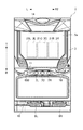
パチスロ1の機能フローについての説明は以上である。次に、図2、図3を参照して、本実施の形態におけるパチスロという1について説明する。図2は、パチスロ1の正面図であり、図3はパチスロ1の斜視図である。
[Pachislot structure]
The functional flow of the
パチスロ1は、リール3L,3C,3Rや回路基板等を収容する筐体となるキャビネット1aと、キャビネット1aの前面側F(図2におけるF側)に対して開閉可能に取り付けられるフロントドア2とフロントドア2の前面側Fにフロントパネル8とを備える。キャビネット1aの内部には、3つのリール3L,3C,3Rが横並びに設けられている。各リール3L,3C,3Rは、円筒状のフレームの周面に、複数の図柄が回転方向に沿って連続的に配置された帯状のシートを貼り付けて構成されている。
The pachi-
フロントドア2の中央には、液晶表示装置5が設けられている。液晶表示装置5は、図3に示すように、フロントドア2の前面側Fであって、フロントドア2とフロントパネル8との間に設けられる。液晶表示装置5は、取付枠により、フロントドア2の上側Tの部分に固定される。
A liquid
また、液晶表示装置5は、図柄表示領域21L,21C,21Rを含む表示画面5aを備え、正面から見て3つのリール3L,3C,3Rに重畳する手前側(図2におけるF側)に位置するように設けられている。図柄表示領域21L,21C,21Rは、3つのリール3L,3C,3Rのそれぞれに対応して設けられており、その背面側R(図2におけるR側)に設けられたリール3L,3C,3Rを透過することが可能な構成を備えている。
The liquid
つまり、図柄表示領域21L,21C,21Rは、表示窓としての機能を果たすものであり、その背後に設けられたリール3L,3C,3Rの回転及びその停止の動作が遊技者側から視認可能となる。また、本実施の形態では、図柄表示領域21L,21C,21Rを含めた表示画面5aの全体を使って、映像の表示が行われ、演出が実行される。
That is, the
図柄表示領域21L,21C,21Rは、その背後に設けられたリール3L,3C,3Rの回転が停止されたとき、リール3L,3C,3Rの表面に配された複数種類の図柄のうち、その枠内における上段、中段及び下段の各領域にそれぞれ1個の図柄(合計で3個)を表示する。また、各図柄表示領域21L,21C,21Rが有する上段、中段及び下段からなる3つの領域のうち予め定められた何れかをそれぞれ組合せてなる擬似的なラインを、入賞か否かの判定を行う対象となるライン(入賞判定ライン)として定義する。
The
フロントドア2には、遊技者による操作の対象となる各種装置が設けられている。メダル投入口10は、遊技者によって外部から投下されるメダルを受け入れるために設けられる。メダル投入口10に受け入れられたメダルは、所定枚数(例えば3枚)を上限として1回の遊技に投入され、所定枚数を超えた分はパチスロ1内部に預けることが可能となる(いわゆるクレジット機能)。
The
ベットボタン11は、パチスロ1内部に預けられているメダルから1回の遊技に投入する枚数を決定するために設けられる。精算ボタン12は、パチスロ1内部に預けられているメダルを外部に引き出すために設けられる。
The
スタートレバーユニット600は、全てのリール3L,3C,3Rの回転を開始するために設けられる。ストップボタン7L,7C,7Rは、3つのリール3L,3C,3Rのそれぞれに対応づけられ、対応するリール3L,3C,3Rの回転を停止するために設けられる。
The
ランプ(LED等)14は、演出内容に応じた点消灯のパターンにて光を出力する。スピーカ9L,9Rは、演出内容に応じた効果音や楽曲等の音を出力する。メダル払出口15は、排出されるメダルを外部に導く。メダル払出口15から排出されたメダルは、メダル受皿16に貯められる。
The lamp (LED or the like) 14 outputs light in a turn-on / off pattern according to the content of the effect. The
[パチスロが備える回路の構成]
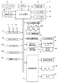
パチスロ1の構造についての説明は以上である。次に、図4及び図5を参照して、本実施の形態におけるパチスロ1が備える回路の構成について説明する。本実施の形態におけるパチスロ1は、主制御回路71、副制御回路72及びこれらと電気的に接続する周辺装置(アクチュエータ)を備える。
[Circuit configuration of pachislot]
This completes the description of the structure of the
<主制御回路>
図4は、本実施の形態におけるパチスロ1の主制御回路71の構成を示す。
<Main control circuit>
FIG. 4 shows a configuration of the
(マイクロコンピュータ)
主制御回路71は、回路基板上に設置されたマイクロコンピュータ30を主たる構成要素としている。マイクロコンピュータ30は、CPU(以下、メインCPU)31、ROM(以下、メインROM)32及びRAM(以下、メインRAM)33により構成される。
(Microcomputer)
The
メインROM32には、メインCPU31により実行される制御プログラム(後述の図31〜図40参照)、内部抽籤テーブル(後述の図14〜図17参照)等のデータテーブル(後述の図10〜図19参照)、副制御回路72に対して各種制御指令(コマンド)を送信するためのデータ等が記憶されている。メインRAM33には、制御プログラムの実行により決定された内部当籤役等の各種データを格納する格納領域(後述の図20〜図22参照)が設けられる。
The
(乱数発生器等)
メインCPU31には、クロックパルス発生回路34、分周器35、乱数発生器36及びサンプリング回路37が接続されている。クロックパルス発生回路34及び分周器35は、クロックパルスを発生する。メインCPU31は、発生されたクロックパルスに基づいて、制御プログラムを実行する。乱数発生器36は、予め定められた範囲の乱数(例えば、0〜65535)を発生する。サンプリング回路37は、発生された乱数の中から1つの値を抽出する。
(Random number generator etc.)
The
(スイッチ等)
マイクロコンピュータ30の入力ポートには、スイッチ等が接続されている。メインCPU31は、スイッチ等の入力を受けて、ステッピングモータ49L,49C,49R等の周辺装置の動作を制御する。ストップスイッチ7Sは、3つのストップボタン7L,7C,7Rのそれぞれが遊技者により押されたこと(停止操作)を検出する。また、スタートスイッチ6Sは、スタートレバー6が遊技者により操作されたこと(開始操作)を検出する。
(Switch etc.)
A switch or the like is connected to the input port of the
メダルセンサ42Sは、メダル投入口10に受け入れられたメダルが前述のセレクタ42内を通過したことを検出する。また、ベットスイッチ11ASは、ベットボタン11Aが遊技者により押されたことを検出する。また、精算スイッチ12Sは、精算ボタン12が遊技者により押されたことを検出する。
The
(周辺装置及び回路)
マイクロコンピュータ30により動作が制御される周辺装置としては、ステッピングモータ49L,49C,49R、7セグ表示器13及びホッパー40がある。また、マイクロコンピュータ30の出力ポートには、各周辺装置の動作を制御するための回路が接続されている。
(Peripheral devices and circuits)
Peripheral devices whose operations are controlled by the
モータ駆動回路39は、各リール3L,3C,3Rに対応して設けられたステッピングモータ49L,49C,49Rの駆動を制御する。リール位置検出回路50は、発光部と受光部とを有する光センサにより、リール3L,3C,3Rが一回転したことを示すリールインデックスを各リール3L,3C,3Rに応じて検出する。
The
ステッピングモータ49L,49C,49Rは、運動量がパルスの出力数に比例し、回転軸を指定された角度で停止させることが可能な構成を備えている。ステッピングモータ49L,49C,49Rの駆動力は、所定の減速比をもったギアを介してリール3L,3C,3Rに伝達される。ステッピングモータ49L,49C,49Rに対して1回のパルスが出力される毎に、リール3L,3C,3Rは一定の角度で回転する。
The stepping
メインCPU31は、リールインデックスを検出してからステッピングモータ49L,49C,49Rに対してパルスを出力した回数をカウントすることによって、リール3L,3C,3Rの回転角度(主に、リール3L,3C,3Rが図柄何個分だけ回転したか)を管理し、リール3L,3C,3Rの表面に配された各図柄の位置を管理するようにしている。
The
表示部駆動回路48は、7セグ表示器13の動作を制御する。また、ホッパー駆動回路41は、ホッパー40の動作を制御する。また、払出完了信号回路51は、ホッパー40に設けられたメダル検出部40Sが行うメダルの検出を管理し、ホッパー40から外部に排出されたメダルが払出枚数に達したか否かをチェックする。
The display
<副制御回路>
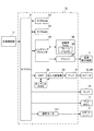
図5は、本実施の形態におけるパチスロ1の副制御回路72の構成を示す。
<Sub control circuit>
FIG. 5 shows a configuration of the
副制御回路72は、主制御回路71と電気的に接続されており、主制御回路71から送信されるコマンドに基づいて演出内容の決定や実行等の処理を行う。副制御回路72は、基本的に、CPU(以下、サブCPU)81、ROM(以下、サブROM)82、RAM(以下、サブRAM)83、レンダリングプロセッサ84、描画用RAM85、ドライバ87、DSP(デジタルシグナルプロセッサ)88、オーディオRAM89、A/D変換器90及びアンプ91を含んで構成されている。
The
サブCPU81は、主制御回路71から送信されたコマンドに応じて、サブROM82に記憶されている制御プログラム(図示せず)に従い、映像、音、光の出力の制御を行う。サブRAM83は、決定された演出内容や演出データを登録する格納領域や、主制御回路71から送信される内部当籤役等の各種データを格納する格納領域が設けられている。サブROM82は、基本的に、プログラム記憶領域とデータ記憶領域によって構成される。
The
プログラム記憶領域には、サブCPU81が実行する制御プログラムが記憶されている。例えば、制御プログラムには、主制御回路71との通信を制御するための主基板通信タスク(図示せず)や、演出用乱数値を抽出し、演出内容(演出データ)の決定及び登録を行うための演出登録タスク(図示せず)、決定した演出内容に基づいて液晶表示装置5による映像の表示を制御する描画制御タスク、ランプ14による光の出力を制御するランプ制御タスク、スピーカ9L,9Rによる音の出力を制御する音声制御タスク等が含まれる。
A control program executed by the
データ記憶領域は、各種データテーブルを記憶する記憶領域、各演出内容を構成する演出データを記憶する記憶領域、映像の作成に関するアニメーションデータを記憶する記憶領域、BGMや効果音に関するサウンドデータを記憶する記憶領域、光の点消灯のパターンに関するランプデータを記憶する記憶領域等が含まれている。 The data storage area stores a storage area for storing various data tables, a storage area for storing effect data constituting each effect content, a storage area for storing animation data related to creation of video, and a sound data related to BGM and sound effects. A storage area, a storage area for storing lamp data related to the light on / off pattern, and the like are included.
また、副制御回路72には、その動作が制御される周辺装置として、液晶表示装置5、スピーカ9L,9R及びランプ14が接続されている。
The
サブCPU81、レンダリングプロセッサ84、描画用RAM85(フレームバッファ86を含む)及びドライバ87は、演出内容により指定されたアニメーションデータに従って映像を作成し、作成した映像を液晶表示装置5により表示する。
The
また、サブCPU81、DSP88、オーディオRAM89、A/D変換器90及びアンプ91は、演出内容により指定されたサウンドデータに従ってBGM等の音をスピーカ9L,9Rにより出力する。また、サブCPU81は、演出内容により指定されたランプデータに従ってランプ14の点灯及び消灯を行う。
Further, the
さらに、サブCPU81は、演出内容により指定されたベットボタンランプデータに従ってベットボタン11の点灯制御を行う。
Further, the
また、サブCPU81は、振動モータ610を駆動制御する。振動モータ610が駆動制御することにより、スタートレバー6が振動する。
Further, the
<スタートレバーユニット>
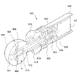
図6は、スタートレバーユニット600の内部構成を示す斜視図である。
<Start lever unit>
FIG. 6 is a perspective view showing an internal configuration of the
図6に示すように、スタートレバーユニット600は、スタートレバー6、クッションゴム614、ホルダ616、ハウジング618、ハーネスカバー620、カラー622、スプリング624、スプリングストッパ626、シャフトエンドキャップ628、センサケース630及びスタートスイッチ6Sによって構成されている。
As shown in FIG. 6, the
さらに、スタートレバー6は、上部半球状体602、略C字型のモータストッパ606、振動モータ610、モータソケット608、シャフト612、及び下部半球状体604によって構成されている。
Further, the
次に、スタートレバーユニット600及びスタートレバー6の構成について詳細に説明する。
Next, the configuration of the
スタートレバー6における、シャフト612に上部半球状体602及び下部半球状体604が固定される。このとき、上部半球状体602とシャフト612との間にモータストッパ606が挟持され。これにより、シャフト612内に振動モータ610が、モータストッパ606によって前方への移動が規制された状態で固定される。
The upper
さらに、シャフト612に、円筒状のクッションゴム614を挿入し、ホルダ616を取り付けて、ホルダ616をハウジング618の内部に設置する。ここで、ホルダ616の後部は略球状に形成されており、ハウジング618の受け部に載置される。さらに、ホルダ616の後方にハーネスカバー620が設置される。さらに、シャフト612にカラー622を取り付けることにより、ホルダ616がハウジング618の受け部に滑動可能に維持される。さらにスプリング624を挿入し、さらにスプリングストッパ626を挿入して、シャフト612にシャフトエンドキャップ628を取り付ける。これにより、ハウジング618を保持し、スタートレバー6を叩くように操作することでスタートレバー6が傾動し、その直後にスタートレバー6は元の位置に戻るようになる。
Further, a
ハウジング618の後部には円筒状のセンサケース630が取り付けられ、このセンサケース630の内部に、スプリングストッパ626に対向させて設置されている。スタートスイッチ6Sの検出子はスプリングストッパ626の傾動に応じて動作する。スタートスイッチ6Sの検出子としてはスイッチ部材が適用可能であり、スタートスイッチ6Sはスイッチ部材の動作に応じてオン、オフ信号を発生する。
A
<操作ボタンユニット>
図7は、操作ボタンユニット200の分解図である。
<Operation button unit>
FIG. 7 is an exploded view of the
操作ボタンユニット200は、ボタン本体部260と、ベットボタン11と、ボタン本体部260と、スプリング300と、発光体ユニット281と、接点ユニット290と、により構成される。
The
ベットボタン11は、ボタン基部250と、ベットボタン11のボタンカバーとしてのボタンカバー部225と、により構成される。ベットボタン11は、遊技者が操作可能に構成され、ボタン本体部260に対し摺動可能に収容される。
The
ボタンカバー部225は、ボタン基部250の上側Tに配置される。このボタンカバー部225は、ベットボタン11のおもて面を構成するボタンカバーとしての機能を有する。ボタンカバー部225は、ボタンキャップ210と、文字シート230と、半透過部材からなるハーフミラー220と、プリズムシート240と、を備える。
The
ボタンキャップ210は、操作ボタンユニット200の一番上側Tに配置されている。このボタンキャップ210は、短外筒部212と、短外筒部212の上側Tを閉塞する面状のボタンキャップ面211と、により構成されている。ボタンキャップ210の下側Bは開口し、短円筒形状に形成されている。短外筒部212には、外方に向かって突出するキャップ突出部214a,214bが対向する位置に一対に設けられている。また、ボタンキャップ210の各キャップ突出部214a,214bの上方(T方向)には、それぞれキャップ係合孔213a,213bが設けられている。
The
ハーフミラー220は、ボタンキャップ210と文字シート230との間に配置されている。ハーフミラー220は、平面円板状のシートにより構成された半透過部材により構成されている。本実施形態によれば、ハーフミラー220は、発光体284から照射される照射光の一部を透過させることができるフィルム素材により構成されている。
The
文字シート230は、ボタンキャップ210の下側Bにおいて、ハーフミラー220と、プリズムシート240との間に配置されている。この文字シート230は、平面円板状の光透過性の樹脂シートにより構成されている。文字シート230のおもて面(T方向)には、異なる色により構成された透光性を有する文字が描かれている。本実施形態によれば、文字シート230には、緑色の文字に構成されたMAX文字231と、桃色の文字に形成されたCHANCE文字232と、がシルク印刷により描かれている。
The
プリズムシート240は、文字シート230の裏側において、ボタンカバー225の一番下に配置される。このプリズムシート240は、平面円板状の光透過性の樹脂シートからなり、発光体284から照射される光を文字シート230方向の面に配光性を持たせる。このため、プリズムシート240に対し発光体284から光を照射することにより、発光体284から照射された光を一様に均一にさせ、文字シート230全体の光量を均一化する。
The
ボタン基部250は、ボタン本体部260の上側Tに配置される。このボタン基部250は、ボタン本体部260に対し摺動可能に収容される。
The
ボタン基部250と、ボタン本体部260との間には、ボタン基部250を下方Bに向かって押し下げする力に対し反発しうるように形成されたスプリング300が設けられている。スプリング300は、略円筒形状に形成されたコイルばねにより形成され、ボタン基部250と、ボタン本体部260とを互いに反発しうるように配置されている。このため、スプリング300は、遊技者がベットボタン11を下方Bに向かって押し下げる力に対して反発する。
A
ボタン本体部260の下方Bには、発光体ユニット281が配置されている。発光体ユニット281は、複数種類の色を照射しうるLEDを有する発光体284と、発光体284を固定する平面状に形成された発光体ユニット基板とを備える。発光体284は、メインCPU31から送信される信号に基づいて、文字シート230に描かれた緑色のMAX文字231と同系色である青色、水色又は緑色等の光や、桃色のCHANCE文字232と同系色である、赤色、桃色又は橙色等の光を照射しうるように形成されている。
A
発光体ユニット281は、螺子286によりボタン本体部260に固定される。さらに、発光体ユニット281の下方Bには、接点ユニット290が配置されている。
The
<ベットボタン>
図8、図9を参照して、ベットボタン11が有する発光体284から文字シート230に描かれた緑色のMAX文字231と同系色、又は桃色のCHANCE文字232と同系色である光を照射した場合について説明する。なお、文字シート230は、ボタンカバー210の裏面に設けられている。
<Bet button>
Referring to FIGS. 8 and 9, light having the same color as the
図8を参照して、文字シート230に描かれた桃色のCHANCE文字232と同系色である赤色、桃色又は橙色の光を発光体284から照射した場合について説明する。
With reference to FIG. 8, the case where the
発光体284は、文字シート230の裏面に対し赤色、桃色又は橙色の光を照射する。そして、発光体284から赤色、桃色又は橙色の光が照射されている文字シート230には、緑色のMAX文字231と桃色のCHANCE文字232とが描かれている。この発光体284から照射されている光の色は、文字シート230に描かれているCHANCE文字232の色と同系色である赤色、桃色又は橙色である。これにより、この発光体284から照射される赤色、桃色又は橙色の光が、文字シート230の裏面からおもて面に向かって透過することにより、文字シート230のおもて面からは、文字シート230に描かれた赤色、桃色又は橙色の光と同系色のCHANCE文字232は見えなくなる。
The
一方で、文字シート230に描かれたMAX文字231は、発光体284から照射される赤色、桃色又は橙色の光とは異なる系統の色である緑色である。そのため、発光体284から照射される赤色、桃色又は橙色の光によってMAX文字231が見えなくなることはない。
On the other hand, the
したがって、発光体284から赤色、桃色又は橙色の光が照射されている場合には、この発光体284から照射される光の色と同系色のCHANCE文字232は光の色に同化されてしまうため、遊技者が文字シート230のおもて面からこの文字シート230を視認した場合であっても、CHANCE文字232を認識することができない。これに対し、発光体284から照射される光と異なる色のMAX文字231は、光の色に同化されないため、遊技者はこのMAX文字231のみを視認することができる。
Therefore, when red, pink or orange light is emitted from the
図9を参照して、文字シート230に描かれた緑色のMAX文字231と同系色である青色、水色又は緑色の光を発光体284から照射した場合について説明する。
With reference to FIG. 9, the case where the light-emitting
発光体284は、文字シート230の裏面に対し青色、水色又は緑色の光を照射する。そして、発光体284から青色、水色又は緑色の光が照射されている文字シート230には、緑色のMAX文字231と桃色のCHANCE文字232とが描かれている。この発光体284から照射されている光の色は、文字シート230に描かれているMAX文字231の色と同系色である青色、水色又は緑色である。これにより、この発光体284から照射される青色、水色又は緑色の光が、文字シート230の裏面からおもて面に向かって透過することにより、文字シート230のおもて面からは、文字シート230に描かれた緑色の光と同系色のMAX文字231は見えなくなる。
The
一方で、文字シート230に描かれたCHANCE文字232は、発光体284から照射される青色、水色又は緑色の光とは異なる系統の色である桃色である。そのため、発光体284から照射される青色、水色又は緑色の光によってCHANCE文字232が見えなくなることはない。
On the other hand, the
したがって、発光体284から青色、水色又は緑色の光が照射されている場合には、この発光体284から照射される光の色と同系色のMAX文字231は光の色に同化されてしまうため、遊技者が文字シート230のおもて面からこの文字シート230を視認した場合であっても、MAX文字231を認識することができない。これに対し、発光体284から照射される光と異なる系統の色のCHANCE文字232は、光の色に同化されないため、遊技者はこのCHANCE文字232のみを視認することができる。
Therefore, when blue, light blue, or green light is emitted from the
このため、発光体284により照射される光の色を、文字シート230に描かれた必要でない機能を示す文字の色と同系色に変えることにより、必要な機能を示す文字のみを文字シート230に表示することができる。
For this reason, by changing the color of the light emitted by the
このことから、1つの操作ボタンユニットに遊技機の複数の機能を設けた場合であっても、遊技者が視認できる文字を変化させることができる。したがって、遊技機の機能に合わせて操作ボタンユニット200に表示される文字を変化させることができる。
From this, even if it is a case where the several function of a game machine is provided in one operation button unit, the character which a player can visually recognize can be changed. Therefore, the characters displayed on the
これにより、1つの操作ボタンユニット200に複数の機能を設けても、操作ボタンユニット200に設けられた機能を遊技者に対し容易に把握させることができる。したがって、例えば演出に用いられる操作ボタンユニット200と、遊技に用いられるメダルの枚数を決定するための操作ボタンユニット200と、を兼用することによりコストの低減を図ることができるとともに、配置スペース上の制約の問題を解消することができる。
Thereby, even if a plurality of functions are provided in one
[メインROMに記憶されているデータテーブルの構成]
パチスロ1が備える回路の構成についての説明は以上である。次に、図10〜図19を参照して、メインROM32に記憶されている各種データテーブルの構成について説明する。
[Configuration of data table stored in main ROM]
This completes the description of the circuit configuration of the
[図柄配置テーブル]
図10を参照して、図柄配置テーブルについて説明する。図柄配置テーブルは、各リール3L,3C,3Rの回転方向における各図柄の位置と、各位置に配された図柄の種類を特定するデータ(以下、図柄コード)とを規定している。
[Design arrangement table]
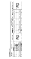
The symbol arrangement table will be described with reference to FIG. The symbol arrangement table defines the position of each symbol in the rotation direction of each
図柄配置テーブルは、リールインデックスが検出されるときに表示窓21L,21C,21R内の中段に存在する図柄の位置を「0」として、リール3L,3C,3Rの回転方向に進む順に、各図柄の位置に対して「0」〜「20」をそれぞれ割り当てている。したがって、リールインデックスが検出されてから図柄何個分の回転が行われたかを管理しつつ、図柄配置テーブルを参照することによって、主として表示窓21L,21C,21Rの中段に存在する図柄の位置及びその図柄の種類を常に管理することが可能となっている。
In the symbol arrangement table, when the reel index is detected, the symbol positions existing in the middle stages of the
[図柄組合せテーブル]
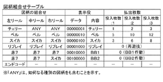
図11を参照して、後述する一般遊技状態、RT1遊技状態、RT2遊技状態の遊技状態毎に規定された図柄組合せテーブルについて説明する。図11は、図柄組合せテーブルを示す。本実施の形態では、入賞判定ラインに沿って各リール3L,3C,3Rにより表示される図柄の組合せが、図柄組合せテーブルにより規定されている図柄の組合せと一致する場合に、入賞と判定され、メダルの払い出し、再遊技の作動、ボーナスゲームの作動といった特典が遊技者に対して与えられる。
[Design combination table]
With reference to FIG. 11, a symbol combination table defined for each of the game states of the general game state, the RT1 game state, and the RT2 game state, which will be described later, will be described. FIG. 11 shows a symbol combination table. In the present embodiment, when the symbol combination displayed by the
図柄組合せテーブルは、特典の種類に応じて予め定められた図柄の組合せと、表示役と、払出枚数とを規定している。表示役は、入賞判定ラインに沿って表示された図柄の組合せを識別するデータである。 The symbol combination table defines a symbol combination, a display combination, and a payout number that are predetermined according to the type of privilege. The display combination is data for identifying a combination of symbols displayed along the winning determination line.
表示役は、各ビットに対して固有の図柄の組合せが割り当てられた1バイトのデータとして表される。例えば、各リール3L,3C,3Rの図柄「ベル」が入賞判定ラインに沿って表示されたとき、表示役として「ベル(00000010)」が決定される。
The display combination is represented as 1-byte data in which a unique symbol combination is assigned to each bit. For example, when the symbol “bell” of each
また、払出枚数として1以上の数値が決定された場合、メダルの払い出しが行われる。本実施の形態では、表示役としてチェリー、ベル又はスイカが決定されたときメダルの払い出しが行われる。 Further, when a numerical value of 1 or more is determined as the payout number, medals are paid out. In the present embodiment, when a cherry, bell, or watermelon is determined as a display combination, medals are paid out.
また、表示役としてリプレイが決定されたとき、再遊技の作動が行われる。表示役としてBB1及びBB2が決定されたとき、ボーナスの作動が行われる。尚、入賞判定ラインに沿って表示された図柄の組合せが、図柄組合せテーブルにより規定されている図柄の組合せの何れとも一致しない場合には、いわゆる「ハズレ」となる。 In addition, when replay is determined as the display combination, replaying is performed. When BB1 and BB2 are determined as display combinations, a bonus operation is performed. If the symbol combination displayed along the winning determination line does not match any of the symbol combinations defined by the symbol combination table, it is a so-called “losing”.
[ボーナス作動時テーブル]
図12を参照して、ボーナス作動時テーブルについて説明する。ボーナス作動時テーブルは、ボーナスの作動が行われるとき及びRTが作動するときに、メインRAM33に設けられた各種格納領域に格納するデータを規定している。
[Bonus operating table]
With reference to FIG. 12, the bonus operation time table will be described. The bonus operation time table defines data to be stored in various storage areas provided in the
実施例の遊技状態には、基本的に、一般遊技状態、RT1遊技状態、RT2遊技状態、BB1遊技状態、BB2遊技状態、及びRB遊技状態がある。 The gaming state of the embodiment basically includes a general gaming state, an RT1 gaming state, an RT2 gaming state, a BB1 gaming state, a BB2 gaming state, and an RB gaming state.
一般遊技状態は、基本的に、いわゆる「出玉率(遊技に賭けられた単位遊技価値に対して遊技者に付与される遊技価値)」の期待値が“1”よりも小さい遊技状態である。また、後述の持越役がない遊技状態であり、他の遊技状態と比べて遊技者にとって最も不利な遊技状態である。 The general game state is basically a game state in which an expected value of a so-called “play rate (game value given to a player for a unit game value bet on a game)” is smaller than “1”. . Further, it is a gaming state without a carryover role described later, and is the most disadvantageous gaming state for the player as compared with other gaming states.
BB1遊技状態及びBB2一般遊技状態は、BB一般遊技状態及びRB遊技状態により構成される遊技状態である。また、BB1遊技状態及びBB2一般遊技状態は、基本的に、「第1種特別役物に係る役物連続作動装置」が作動しているゲームにより構成される遊技状態である。 The BB1 gaming state and the BB2 general gaming state are gaming states configured by the BB general gaming state and the RB gaming state. Further, the BB1 gaming state and the BB2 general gaming state are basically gaming states configured by a game in which the “actual accessory continuous actuating device related to the first type special accessory” is operating.
RB遊技状態は、基本的に、「第1種特別役物」が作動しているゲームにより構成される遊技状態である。 The RB gaming state is basically a gaming state constituted by a game in which the “first type special character” is operating.
BB1遊技状態の発生条件は、BB1の成立である。獲得枚数(例えば、いわゆる「純増枚数」或いは「払出枚数」)が所定枚数(例えば、346枚)以上となることにより遊技状態の移行条件が成立(充足)し、遊技状態が一般遊技状態へ移行する。 The condition for generating the BB1 gaming state is establishment of BB1. When the acquired number (for example, so-called “pure increase number” or “payout number”) exceeds a predetermined number (for example, 346), the game state transition condition is satisfied (satisfied), and the gaming state shifts to the general gaming state. To do.
BB2遊技状態の発生条件は、BB2の成立である。獲得枚数(例えば、いわゆる「純増枚数」或いは「払出枚数」)が所定枚数(例えば、246枚)以上となることにより遊技状態の移行条件が成立(充足)し、遊技状態が一般遊技状態へ移行する。 The condition for generating the BB2 gaming state is establishment of BB2. The game state transition condition is satisfied (satisfied) when the acquired number (for example, so-called “pure increase number” or “payout number”) is equal to or greater than a predetermined number (for example, 246), and the gaming state shifts to the general gaming state. To do.
作動中フラグは、作動している遊技状態(現在の遊技状態)を識別するための情報である。本実施例の作動中フラグには、RB遊技状態が作動しているか否かを識別するためのRB作動中フラグと、BB1(第1種特別役物に係る役物連続作動装置)が作動しているか否かを識別するためのBB1作動中フラグと、BB2(第1種特別役物に係る役物連続作動装置)が作動しているか否かを識別するためのBB2作動中フラグと、RT1が作動しているか否かを識別するためのRT1作動中フラグと、RT2が作動しているか否かを識別するためのRT2作動中フラグと、がある。以下では、BB1作動中フラグ及びBB2作動中フラグを「ボーナス作動中フラグ」と総称する。 The operating flag is information for identifying an operating gaming state (current gaming state). In the operating flag of this embodiment, an RB operating flag for identifying whether or not the RB gaming state is operating, and BB1 (a continuous action device for a first type special accessory) are operated. A BB1 operating flag for identifying whether or not the BB2 is operating, a BB2 operating flag for identifying whether or not BB2 (a continuous action device related to the first type special object) is operating, and RT1 There is an RT1 operating flag for identifying whether or not RT2 is operating, and an RT2 operating flag for identifying whether or not RT2 is operating. Hereinafter, the BB1 operating flag and the BB2 operating flag are collectively referred to as “bonus operating flag”.
BB1の作動は、規定枚数(本実施の形態では、346枚)に達するメダルの払い出しが行われた場合に終了する。BB2の作動は、規定枚数(本実施の形態では、246枚)に達するメダルの払い出しが行われた場合に終了する。RBの作動は、規定回数(本実施の形態では、8回)に達する遊技が行われた場合、規定回数(本実施の形態では、8回)に達する入賞が有った場合、又は、BB1又はBB2の作動が終了した場合の何れかによって終了する。ボーナス終了枚数カウンタ、遊技可能回数カウンタ及び入賞可能回数カウンタは、ボーナスの終了契機となる上記規定枚数或いは上記規定回数に達したか否かを管理するためのデータである。 The operation of BB1 ends when the medals are paid out to reach the prescribed number (346 in the present embodiment). The operation of BB2 ends when medals are paid out to reach the prescribed number (246 in this embodiment). The RB is activated when a game that reaches the specified number of times (8 times in the present embodiment) is performed, when there is a winning that reaches the specified number of times (8 times in the present embodiment), or BB1 Alternatively, the operation is terminated when either the operation of BB2 is completed. The bonus end number counter, the possible game number counter, and the possible winning number counter are data for managing whether or not the specified number of times or the specified number of times as a trigger end timing of the bonus has been reached.
より具体的には、ボーナス作動時テーブルにより規定されている数値が上記各カウンタに格納され、ボーナスの作動を通じてその減算が行われていく。その結果、各カウンタの値が「0」に更新されたことを条件に該当ボーナスの作動が終了する。 More specifically, numerical values defined by the bonus operation time table are stored in the respective counters, and the subtraction is performed through the operation of the bonus. As a result, the operation of the corresponding bonus is completed on condition that the value of each counter is updated to “0”.
[内部抽籤テーブル決定テーブル]
図13を参照して、内部抽籤テーブル決定テーブルについて説明する。内部抽籤テーブル決定テーブルは、遊技状態に対応して、内部抽籤テーブルの種別の情報及び抽籤回数の情報を規定している。実施例では、遊技状態として、一般遊技状態、RT1遊技状態、RT2遊技状態、BB1一般遊技状態及びBB2遊技状態が設けられている。以下では、RT1遊技状態、及び、RT2遊技状態を「RT遊技状態」と総称する。また、BB1及びBB2を以下「ボーナス」と総称する。
[Internal lottery table determination table]
The internal lottery table determination table will be described with reference to FIG. The internal lottery table determination table defines information on the type of the internal lottery table and information on the number of lotteries corresponding to the gaming state. In the embodiment, a general gaming state, an RT1 gaming state, an RT2 gaming state, a BB1 general gaming state, and a BB2 gaming state are provided as gaming states. Hereinafter, the RT1 gaming state and the RT2 gaming state are collectively referred to as “RT gaming state”. Further, BB1 and BB2 are hereinafter collectively referred to as “bonus”.
遊技状態は、内部抽籤処理(後述の図35参照)において決定される可能性のある内部当籤役の種類、内部抽籤処理において内部当籤役が決定される確率、最大の滑り駒数(最大滑り駒数)、及びボーナスの作動が行われているか否か等により区別される状態である。なお、実施例では、BB一般遊技状態及びRB遊技状態がボーナスの作動が行われている状態となる。 The gaming state is the type of internal winning combination that may be determined in the internal lottery process (see FIG. 35 to be described later), the probability that an internal winning combination is determined in the internal lottery process, and the maximum number of sliding pieces (maximum sliding piece) Number) and whether or not the bonus is activated. In the embodiment, the BB general gaming state and the RB gaming state are in a state where the bonus is activated.
ここで、一般遊技状態、RT1遊技状態、及びRT2遊技状態は、後述のリプレイが内部当籤役として決定される確率がそれぞれ異なる状態である。実施例では、リプレイが内部当籤役として決定される確率は、RT2遊技状態が最も高く、RT1遊技状態が次に高く、一般遊技状態が最も低い。 Here, the general gaming state, the RT1 gaming state, and the RT2 gaming state are states having different probabilities that a replay to be described later is determined as an internal winning combination. In the embodiment, the probability that the replay is determined as an internal winning combination is highest in the RT2 gaming state, next in the RT1 gaming state, and lowest in the general gaming state.
抽籤回数は、サンプリング回路37により抽出された一の乱数値(いわゆる判定用乱数値)から後述の抽籤値をメインCPU31が減算する最大の回数である。
The number of lotteries is the maximum number of times that the
[内部抽籤テーブル]
図14〜図17を参照して、内部抽籤テーブルについて説明する。内部抽籤テーブルは、当籤番号に応じて、データポインタと抽籤値とを規定している。データポインタは、内部抽籤テーブルを参照して行う抽籤の結果として取得されるデータであり、後述の内部当籤役決定テーブルにより規定されている内部当籤役を指定するためのデータである。データポインタには、小役・リプレイ用データポインタ及びボーナス用データポインタが設けられている。
[Internal lottery table]
The internal lottery table will be described with reference to FIGS. The internal lottery table defines a data pointer and a lottery value according to the winning number. The data pointer is data acquired as a result of lottery performed with reference to the internal lottery table, and is data for designating an internal winning combination defined by an internal winning combination determination table described later. The data pointer is provided with a small role / replay data pointer and a bonus data pointer.
本実施の形態では、予め定められた数値の範囲「0〜65535」から抽出される乱数値を、各当籤番号に応じた抽籤値で順次減算し、減算の結果が負となったか否か(いわゆる「桁かり」が生じたか否か)の判定を行うことによって内部的な抽籤が行われる。 In the present embodiment, random numbers extracted from a predetermined numerical range “0 to 65535” are sequentially subtracted by lottery values corresponding to each winning number, and whether or not the result of the subtraction is negative ( An internal lottery is performed by determining whether or not a so-called “digit” has occurred.
したがって、抽籤値として規定されている数値が大きいほど、これが割り当てられたデータ(つまり、データポインタ)が決定される確率が高い。尚、各当籤番号の当籤確率は、「各当籤番号に対応する抽籤値/抽出される可能性のある全ての乱数値の個数(65536)」によって表すことができる。 Therefore, the larger the numerical value defined as the lottery value, the higher the probability that the data (that is, the data pointer) to which it is assigned will be determined. The winning probability of each winning number can be represented by “the lottery value corresponding to each winning number / the number of all random numbers that may be extracted (65536)”.
図14は、一般遊技状態用内部抽籤テーブルを示す。図15は、RT1遊技状態用内部抽籤テーブルを示す。図16は、RT2遊技状態用内部抽籤テーブルを示す。図17は、RB作動中用内部抽籤テーブルを示す。本実施の形態では、ボーナスの作動が行われているか否かといった状況に応じて、複数種類の内部抽籤テーブルを使い分けることにより、決定される内部当籤役の種類や当籤確率を変動させ、この結果、遊技者が抱く期待に起伏が生じるようにしている。 FIG. 14 shows an internal lottery table for a general gaming state. FIG. 15 shows an internal lottery table for RT1 gaming state. FIG. 16 shows an internal lottery table for RT2 gaming state. FIG. 17 shows an internal lottery table for RB operation. In the present embodiment, depending on the situation such as whether or not the bonus is activated, the type of internal winning combination and the winning probability that are determined are varied by using different types of internal lottery tables. , The expectation that the player holds is undulating.
[内部当籤役決定テーブル]
図18及び図19を参照して、内部当籤役決定テーブルについて説明する。内部当籤役決定テーブルは、データポインタに応じて内部当籤役を規定している。データポインタが決定されると、内部当籤役が一義的に取得される構成となっている。
[Internal winning combination determination table]
The internal winning combination determination table will be described with reference to FIGS. The internal winning combination determination table defines an internal winning combination in accordance with the data pointer. When the data pointer is determined, the internal winning combination is uniquely acquired.
内部当籤役は、入賞判定ラインに沿って表示を許可する各リール3L,3C,3Lの図柄の組合せを識別するデータである。内部当籤役は、表示役と同様に、各ビットに対して固有の図柄の組合せが割り当てられた1バイトのデータとして表される。尚、データポインタが「0」のとき、内部当籤役の内容は「ハズレ」となるが、これは前述の図柄組合せテーブルにより規定されている図柄の組合せの表示が何れも許可されないことを示す。
The internal winning combination is data for identifying a combination of symbols of each
図18は、小役・リプレイ用内部当籤役決定テーブルを示す。小役・リプレイ用内部当籤役決定テーブルは、メダルの払い出しに係る内部当籤役又は再遊技の作動に係る内部当籤役を規定している。図19は、ボーナス用内部当籤役決定テーブルを示す。ボーナス用内部当籤役決定テーブルは、ボーナスの作動に係る内部当籤役を規定している。 FIG. 18 shows a small combination / replay internal winning combination determination table. The small winning combination / replay internal winning combination determination table defines an internal winning combination relating to the payout of medals or an internal winning combination relating to the operation of replay. FIG. 19 shows a bonus internal winning combination determination table. The bonus internal winning combination determination table defines internal winning combinations related to the operation of the bonus.
[メインRAMに設けられる格納領域の構成]
メインROM32に記憶されているデータテーブルの内容についての説明は以上である。次に、図20〜図22を参照して、メインRAM33に設けられている各種格納領域の構成について説明する。
[Configuration of storage area provided in main RAM]
This completes the description of the contents of the data table stored in the
[内部当籤役格納領域]
図20を参照して、内部当籤役格納領域の構成について説明する。内部当籤役格納領域は、前述の1バイトのデータにより表される内部当籤役を格納する。ビットに「1」が立っているとき、該当する図柄の組合せの表示が許可される。尚、全ビットが「0」であるとき、その内容はハズレとなる。
[Internal winning combination storage area]
The configuration of the internal winning combination storing area will be described with reference to FIG. The internal winning combination storing area stores the internal winning combination represented by the above-mentioned 1-byte data. When the bit is set to “1”, display of the corresponding symbol combination is permitted. When all bits are “0”, the content is lost.
尚、メインRAM33には、前述の表示役が格納される表示役格納領域が設けられている。表示役格納領域の構成は、内部当籤役格納領域の構成と同様となっている。ビットに「1」が立っているとき、該当する図柄の組合せが入賞判定ラインに沿って表示されたことになる。
The
[持越役格納領域]
図21を参照して、持越役格納領域の構成について説明する。
[Coverage storage area]
The configuration of the carryover combination storage area will be described with reference to FIG.
前述の抽籤の結果、ボーナスの作動に係る内部当籤役が決定されたときは、これが持越役格納領域に格納される。持越役格納領域に格納されたボーナスの作動に係る内部当籤役(以下、持越役)は、対応する図柄の組合せが入賞判定ラインに表示されるまで、その内容がクリアされずに保持される構成となっている。そして、持越役格納領域に持越役が格納されている間は、前述の抽籤の結果にかかわらず、これが内部当籤役格納領域に格納される。 As a result of the aforementioned lottery, when an internal winning combination relating to the operation of the bonus is determined, this is stored in the carryover combination storage area. The internal winning combination (hereinafter referred to as the carryover combination) related to the operation of the bonus stored in the carryover combination storage area is retained without being cleared until the corresponding symbol combination is displayed on the winning determination line. It has become. And while the carryover combination is stored in the carryover combination storage area, it is stored in the internal winning combination storage area regardless of the result of the lottery described above.
[作動中フラグ格納領域]
図22を参照して、作動中フラグ格納領域の構成について説明する。
[Operation flag storage area]
The configuration of the operating flag storage area will be described with reference to FIG.
作動中フラグ格納領域は、1バイトからなる作動中フラグを格納する。作動中フラグは、各ビットに対して固有のボーナスが割り当てられている。ビットに「1」が立っているとき、該当するボーナスの作動が行われている。尚、全ビットが「0」であるときの状態を一般遊技状態と定義する。 The operating flag storage area stores an operating flag consisting of 1 byte. The operating flag has a unique bonus assigned to each bit. When “1” is set in the bit, the corresponding bonus is activated. The state when all bits are “0” is defined as a general gaming state.
[コマンドパラメータの説明]
メインRAM33に設けられる各種格納領域の構成についての説明は以上である。次に、図23及び図24を参照して、コマンドパラメータについて説明する。
[Description of command parameters]
This completes the description of the configuration of the various storage areas provided in the
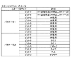
まず、入力状態コマンドは、ボタンの入力時に副制御回路72へ送信されるコマンドであり、図23に示した入力状態コマンドパラメータは、8ビットで構成されている。さらに、各ビットとボタンの種別が対応付けられており、例えば、ビット0に「1」が格納されている場合、左停止ボタンの入力がされたことを示している。
First, the input state command is a command transmitted to the
また、スタートコマンドは、スタートレバー検知後の抽籤結果取得時に副制御回路72へ送信されるコマンドであり、図24に示したスタートコマンドパラメータは、パラメータ1及びパラメータ2の2つのパラメータで構成されている。さらに、パラメータ1及びパラメータ2のそれぞれのパラメータは8ビットで構成されている。
The start command is a command transmitted to the
パラメータ1は、ビット6及びビット7がRT遊技状態を識別するために使用される領域であり、ビット6及びビット7の組合せが、「00」の場合、RTなし(一般遊技状態)であり、「01」の場合、RT1であり、「10」の場合、RT2である。
パラメータ2は、ビット0〜ビット5が内部当籤役を識別するために使用される領域であり、例えば、ビット2に「1」が格納されている場合、スイカに内部当籤したことを示している。
その他のコマンドの内容には、「初期化コマンド」、「デモ表示コマンド」、「メダル投入コマンド」、「リール回転開始コマンド」、「リール停止コマンド」、「表示コマンド」、「払出終了コマンド」、「ボーナス終了コマンド」及び「ボーナス開始コマンド」等がある。 Other command contents include “initialization command”, “demo display command”, “medal insertion command”, “reel rotation start command”, “reel stop command”, “display command”, “payout end command”, There are a “bonus end command” and a “bonus start command”.
これらのコマンドの送信時期は、初期化コマンドは「設定変更時」、デモ表示コマンドは「遊技終了から10秒経過時」、メダル投入コマンドは「メダル投入時」、リール回転開始コマンドは「リール回転開始時」、リール停止コマンドは「リール停止時」、表示コマンドは「表示役成立時」、払出終了コマンドは「払出し終了時」、ボーナス終了コマンドは「ボーナス入賞時」、ボーナス開始コマンドは「ボーナス表示時」である。 The transmission timing of these commands is as follows: “Initialization command is“ when setting is changed ”, demo display command is“ when 10 seconds have elapsed from the end of the game ”, medal insertion command is“ when medal is inserted ”, and reel rotation start command is“ reel rotation ” "Start", reel stop command is "reel stop", display command is "when display combination is established", payout end command is "payout end", bonus end command is "bonus winning", bonus start command is "bonus "When displaying".
これらのコマンドの送信処理としては、コマンド送信イベントが発生した場合に、まず通信データ格納領域に送信コマンドをセットし、セットされた送信コマンドを割り込み処理で送信する。 As a transmission process of these commands, when a command transmission event occurs, first, a transmission command is set in the communication data storage area, and the set transmission command is transmitted by an interrupt process.
[サブROMに記憶されているデータテーブルの構成]
コマンドパラメータについての説明は以上である。次に、図25〜図30を参照して、サブROM82に記憶されている各種データテーブルの構成について説明する。
[Configuration of data table stored in sub-ROM]
This completes the description of the command parameters. Next, the configuration of various data tables stored in the
[演出構成テーブル]
図25を参照して、演出構成テーブルについて説明する。演出構成テーブルは、演出番号に応じて、演出内容及びBETボタンランプデータのデータ種別を規定している。
[Direction composition table]
With reference to FIG. 25, the effect composition table will be described. The effect configuration table defines the contents of the effect and the BET button lamp data according to the effect number.
演出番号が0の場合、通常演出が行われる。この通常演出は、スピーカ9R,9Lから出力される音による演出及び/又はランプ14から発光される光による演出である。
When the production number is 0, a normal production is performed. This normal effect is an effect by sound output from the
演出番号が1の場合、キャラクタA演出が行われる。この演出は、表示画面5aにキャラクタAが表示される演出である。
When the production number is 1, the character A production is performed. This effect is an effect in which the character A is displayed on the
演出番号が2の場合、キャラクタB演出が行われる。この演出は、表示画面5aにキャラクタBが表示される演出である。
When the production number is 2, the character B production is performed. This effect is an effect in which the character B is displayed on the
演出番号が3の場合、キャラクタC演出が行われる。この演出は、表示画面5aにキャラクタCが表示される演出である。
When the production number is 3, the character C production is performed. This effect is an effect in which the character C is displayed on the
演出番号が4の場合、ボタン操作前演出1が行われる。この演出は、リール3L,3C,3Rの変動開始時から第3停止時までの間ベットボタン11を青色で点灯させる演出である。ベットボタン11を青色で点灯させることにより、ベットボタン11が「CHANCE」と表示される。
When the production number is 4,
演出番号が5の場合、ボタン操作前演出2が行われる。この演出は、リール3L,3C,3Rの変動開始時から第3停止時までの間ベットボタン11を水色で点灯させる演出である。ベットボタン11を水色で点灯させることにより、ベットボタン11が「CHANCE」と表示される。
When the production number is 5,
演出番号が6の場合、ボタン操作前演出3が行われる。この演出は、リール3L,3C,3Rの変動開始時から第3停止時までの間ベットボタン11を緑色で点灯させる演出である。ベットボタン11を緑色で点灯させることにより、ベットボタン11が「CHANCE」と表示される。
When the production number is 6,
ここで、BETボタンランプデータのデータ種別について説明する。 Here, the data type of the BET button lamp data will be described.
スタート時(スタートレバーON時)には、RT遊技状態に対応したデータ種別が、演出番号が0〜6のいずれにもかかわらずセットされる。演出番号が0〜3の場合、セットされたデータ種別が表示役成立時(表示コマンド受信時)まで変わらず維持される。演出番号が4〜6の場合、リール3L,3C,3Rの変動開始時から第3停止時のまで間は、演出番号に対応したデータ種別がセットされ、表示役成立時(表示コマンド受信時)にRT遊技状態に対応したデータ種別がリセットされる。
At the start (when the start lever is ON), the data type corresponding to the RT gaming state is set regardless of any of the effect numbers 0-6. When the production number is 0 to 3, the set data type is kept unchanged until the display combination is established (when the display command is received). When the production number is 4-6, the data type corresponding to the production number is set from the start of fluctuation of the
さらに、後述の図26及び図27で説明するように、RT遊技状態が「RTなし」の場合、赤色でベットボタンが点灯し、RT遊技状態が「RT1」の場合、桃色でベットボタンが点灯し、RT遊技状態が「RT2」場合、橙色でベットボタンが点灯する。 Further, as will be described later with reference to FIGS. 26 and 27, when the RT gaming state is “no RT”, the red bet button is lit, and when the RT gaming state is “RT1”, the bet button is lit in pink. When the RT gaming state is “RT2”, the bet button is lit in orange.
よって、演出番号が0〜3の場合、ベットボタン11が「MAX」と表示され、表示役成立時(表示コマンド受信時)まで変わらない。
Therefore, when the production number is 0 to 3, the
また、演出番号が4〜6の場合、スタート時(スタートレバーON時)及び表示役成立時(表示コマンド受信時)にベットボタン11が「MAX」と表示される。
When the production numbers are 4 to 6, the
[BETボタンランプデータテーブル]
図26を参照して、BETボタンランプデータテーブルについて説明する。BETボタンランプデータテーブルは、データ種別とBETボタンランプデータとの対応関係を規定している。
[BET button lamp data table]
The BET button lamp data table will be described with reference to FIG. The BET button lamp data table defines the correspondence between data types and BET button lamp data.
データ種別「00H」は、赤色点灯ランプデータと、データ種別「01H」は、桃色点灯ランプデータと、データ種別「02H」は、橙色点灯ランプデータと、データ種別「03H」は、青色点灯ランプデータと、データ種別「04H」は、水色点灯ランプデータと、データ種別「05H」は、緑色点灯ランプデータと、それぞれ対応している。 The data type “00H” is red lighting lamp data, the data type “01H” is pink lighting lamp data, the data type “02H” is orange lighting lamp data, and the data type “03H” is blue lighting lamp data. The data type “04H” corresponds to the light blue lamp data, and the data type “05H” corresponds to the green light lamp data.
[データ種別決定テーブル]
図27を参照して、データ種別決定テーブルについて説明する。データ種別決定テーブルは、RT遊技状態とデータ種別との対応関係を規定している。
[Data type determination table]
The data type determination table will be described with reference to FIG. The data type determination table defines the correspondence between the RT gaming state and the data type.
RT遊技状態「RTなし」は、データ種別「00H」と、RT遊技状態「RT1」は、データ種別「01H」と、RT遊技状態「RT2」は、データ種別「02H」と、それぞれ対応している。 The RT gaming state “No RT” corresponds to the data type “00H”, the RT gaming state “RT1” corresponds to the data type “01H”, and the RT gaming state “RT2” corresponds to the data type “02H”. Yes.
[振動態様抽籤テーブル]
図28を参照して、振動態様抽籤テーブルについて説明する。振動態様抽籤テーブルは、振動データに応じて、振動内容及び内部当籤役毎の抽籤値を規定している。
[Vibration mode lottery table]
The vibration mode lottery table will be described with reference to FIG. The vibration mode lottery table defines the vibration content and the lottery value for each internal winning combination in accordance with the vibration data.
本実施の形態では、予め定められた数値の範囲「0〜1023」から抽出される乱数値を、各演出種別番号に応じた抽籤値で順次減算し、減算の結果が負となったか否か(いわゆる「桁かり」が生じたか否か)の判定を行うことによって内部的な抽籤が行われる。 In the present embodiment, random numbers extracted from a predetermined numerical range “0 to 1023” are sequentially subtracted by lottery values corresponding to each effect type number, and whether or not the result of the subtraction becomes negative An internal lottery is performed by determining whether or not a so-called “digit” has occurred.
したがって、抽籤値として規定されている数値が大きいほど、これが割り当てられたデータ(つまり、振動データ)が決定される確率が高い。尚、各振動データの当籤確率は、「各振動データに対応する抽籤値/抽出される可能性のある全ての乱数値の個数(1024)」によって表すことができる。 Therefore, the larger the numerical value defined as the lottery value, the higher the probability that the data (that is, vibration data) to which it is assigned is determined. The winning probability of each vibration data can be represented by “the lottery value corresponding to each vibration data / the number of all random values that may be extracted (1024)”.
ここで、振動内容について説明する。小振動、中振動及び大振動とは、スタートレバー6が振動する際の振幅の大きさを表している。大振動が、振幅が一番大きく、中振動が、振幅が2番目に大きく、小振動が、振幅が3番目に大きい(一番小さい)。また、間欠振動とは、振動が断続的に行われるものであり、一定の周期で、スタートレバー6が振動している時間帯と振動していない時間帯が交互に繰り返される。
Here, the vibration content will be described. Small vibration, medium vibration and large vibration represent the magnitude of the amplitude when the
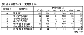
[演出番号抽籤テーブル(変動開始時)]
図29を参照して、演出番号抽籤テーブル(変動開始時)について説明する。演出番号抽籤テーブル(変動開始時)は、演出番号に応じて、演出内容及び内部当籤役毎の抽籤値を規定している。このテーブルは、図50で後述する演出抽籤処理にて参照される。
[Direction number lottery table (at the start of change)]
With reference to FIG. 29, an effect number lottery table (at the start of variation) will be described. The production number lottery table (at the start of variation) defines the production contents and the lottery value for each internal winning combination in accordance with the production number. This table is referred to in the effect lottery process described later with reference to FIG.
本実施の形態では、予め定められた数値の範囲「0〜1023」から抽出される乱数値を、各演出種別番号に応じた抽籤値で順次減算し、減算の結果が負となったか否か(いわゆる「桁かり」が生じたか否か)の判定を行うことによって内部的な抽籤が行われる。 In the present embodiment, random numbers extracted from a predetermined numerical range “0 to 1023” are sequentially subtracted by lottery values corresponding to each effect type number, and whether or not the result of the subtraction becomes negative An internal lottery is performed by determining whether or not a so-called “digit” has occurred.
したがって、抽籤値として規定されている数値が大きいほど、これが割り当てられたデータ(つまり、演出番号)が決定される確率が高い。尚、各演出番号の当籤確率は、「各演出番号に対応する抽籤値/抽出される可能性のある全ての乱数値の個数(1024)」によって表すことができる。 Therefore, the larger the numerical value defined as the lottery value, the higher the probability that the data (that is, the production number) to which it is assigned will be determined. The winning probability of each effect number can be represented by “the lottery value corresponding to each effect number / the number of all random values that may be extracted (1024)”.
なお、演出内容については、図25の演出構成テーブルの説明で上述したとおりである。 The contents of the effect are as described above in the description of the effect configuration table in FIG.
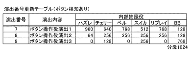
[演出番号更新テーブル(ボタン検知あり)]
図30を参照して、演出番号更新テーブル(ボタン検知あり)について説明する。演出番号更新テーブル(ボタン検知あり)は、演出番号に応じて、演出内容及び内部当籤役毎の抽籤値を規定している。このテーブルは、図52で後述する入力状態コマンド受信処理にて参照される。具体的には、ベットボタン11が青色、水色、緑色の何れかに点灯し、ベットボタン11が「CHANCE」と表示されている際に、ベットボタン11の押圧操作がなされた場合に参照される。
[Production number update table (with button detection)]
With reference to FIG. 30, an effect number update table (with button detection) will be described. The production number update table (with button detection) defines the production contents and lottery values for each internal winning combination in accordance with the production number. This table is referred to in input state command reception processing described later with reference to FIG. Specifically, the reference is made when the
本実施の形態では、予め定められた数値の範囲「0〜1023」から抽出される乱数値を、各演出種別番号に応じた抽籤値で順次減算し、減算の結果が負となったか否か(いわゆる「桁かり」が生じたか否か)の判定を行うことによって内部的な抽籤が行われる。 In the present embodiment, random numbers extracted from a predetermined numerical range “0 to 1023” are sequentially subtracted by lottery values corresponding to each effect type number, and whether or not the result of the subtraction becomes negative An internal lottery is performed by determining whether or not a so-called “digit” has occurred.
したがって、抽籤値として規定されている数値が大きいほど、これが割り当てられたデータ(つまり、演出番号)が決定される確率が高い。尚、各演出番号の当籤確率は、「各演出番号に対応する抽籤値/抽出される可能性のある全ての乱数値の個数(1024)」によって表すことができる。 Therefore, the larger the numerical value defined as the lottery value, the higher the probability that the data (that is, the production number) to which it is assigned will be determined. The winning probability of each effect number can be represented by “the lottery value corresponding to each effect number / the number of all random values that may be extracted (1024)”.
演出内容については、ボタン操作後演出1は、キャラクタDが表示画面5aに表示される演出である。また、ボタン操作後演出2は、キャラクタEが表示画面5aに表示される演出である。さらに、ボタン操作後演出3は、キャラクタFが表示画面5aに表示される演出である。
As for the contents of the effect, the
以上より、ベットボタン11が青色、水色、緑色の何れかに点灯し、ベットボタン11が「CHANCE」と表示されている際に、ベットボタン11の押圧操作がなされた場合、キャラクタD〜Fの何れかが抽籤結果に応じて表示画面5aに表示される。
As described above, when the
[パチスロにおいて実行されるプログラムフロー]
サブROM82に記憶されている各種データテーブルの構成についての説明は以上である。次に、図31〜図40を参照して、主制御回路71のメインCPU31により実行されるプログラムの内容について説明する。
[Program flow executed in pachislot]
The description of the configuration of the various data tables stored in the
[主制御回路のメインCPUの制御によるメインフローチャート]
まず、図31を参照して、メインCPU31の制御によるメインフローチャートについて説明する。パチスロ1に電源が投入されると、はじめに、メインCPU31は、初期化処理を行う(S1)。次に、メインCPU31は、メインRAM33における指定格納領域のクリアを行う(S2)。この処理では、例えば、内部当籤役格納領域(図20参照)や表示役格納領域(図20参照)等、1回の遊技毎に消去が必要となる格納領域に格納されたデータがクリアされる。
[Main flowchart by control of main CPU of main control circuit]
First, with reference to FIG. 31, the main flowchart by control of the main CPU31 is demonstrated. When power is turned on to the pachi-
次に、メインCPU31は、ボーナス作動監視処理を行う(S3)。この処理では、BB1作動中フラグ又はBB2作動中フラグがオンである場合には、RB遊技状態が終了しても続けてRB遊技状態となるようにRB作動中フラグをオンに更新する処理が行われる。
Next, the
次に、メインCPU31は、後で図32を参照して説明するメダル受付・スタートチェック処理を行う(S4)。この処理では、メダルセンサ42Sやスタートスイッチ6Sの入力のチェック等が行われる。
Next, the
次に、メインCPU31は、乱数値を抽出し、メインRAM33に設けられた乱数値格納領域に格納する(S5)。次に、メインCPU31は、後で図35を参照して説明する内部抽籤処理を行う(S6)。この処理では、乱数値に基づいた抽籤により内部当籤役の決定が行われる。次に、メインCPU31は、スタートコマンドをセットし、スタートコマンドを副制御回路72に対して送信する(S7)。スタートコマンドは、内部当籤役等を特定するパラメータを含んで構成される。
Next, the
次に、メインCPU31は、前回の遊技におけるリール回転が開始してから4.1秒経過しているか否かを判別する(S8)。メインCPU31は、前回の遊技におけるリール回転が開始してから4.1秒経過していると判別したときには、遊技時間管理タイマに4.1秒をセットする処理を行う(S10)。前回の遊技におけるリール回転が開始してから4.1秒経過していないと判別したときには、ウェイト時間の消化処理(ウェイト処理)を行う(S9)。この処理では、前回の遊技におけるリール回転が開始してから4.1秒が経過するまでの間、遊技者のゲームを開始する操作に基づく入力を無効にする処理が行われる。次に、メインCPU31は、遊技時間管理タイマに4.1秒をセットする処理(S10)を行い、S10の処理の次に、メインCPU31は、リール回転開始コマンドをセットし、リール回転開始コマンドを副制御回路72に対して送信する(S11)。
Next, the
次に、メインCPU31は、全リール3L,3C,3Rの回転開始を要求する(S12)。尚、全リール3L,3C,3Rの回転開始が要求されると、一定の周期(1.1173msec)で実行される割込処理(図示せず)によってステッピングモータ49L,49C,49Rの駆動が制御され、各リール3L,3C,3Rの回転が開始される。
Next, the
次に、メインCPU31は、後で図36を参照して説明するリール停止制御処理を行う(S13)。この処理では、ストップスイッチ7Sの入力のチェックが行われ、ストップボタンが押されたタイミングと内部当籤役とに基づいて該当リールの回転が停止される。
Next, the
次に、メインCPU31は、図柄組合せテーブルを参照し、有効ラインに沿って表示される図柄の組み合わせに基づいて表示役等を決定する(S14)。参照の結果、入賞判定ラインに沿って表示された図柄の組合せが図柄組合せテーブル(図11参照)により規定されている図柄の組合せと一致する場合、対応する表示役及び払出枚数が決定される。次に、メインCPU31は、表示コマンドをセットし、表示コマンドを副制御回路72に対して送信する(S15)。表示コマンドは、表示役や払出枚数等を特定するパラメータを含んで構成される。
Next, the
次に、メインCPU31は、メダル払出処理を行う(S16)。この処理では、決定された払出枚数に基づいて、ホッパー40の駆動やクレジット枚数の更新が行われる。次に、メインCPU31は、払出枚数に基づいて、ボーナス終了枚数カウンタを更新する(S17)。この処理では、払出枚数として決定された数値がボーナス終了枚数カウンタから減算される。
Next, the
次に、メインCPU31は、ボーナス作動中フラグ(BB1作動中フラグ又はBB2作動中フラグ)がオンであるか否かを判別する(S18)。メインCPU31は、ボーナス作動中フラグがオンであると判別したときには、後で図38を参照して説明するボーナス終了チェック処理を行う(S19)。この処理では、ボーナスの終了契機を管理するための各種カウンタを参照して、ボーナスの作動を終了するか否かがチェックされる。S18においてボーナス作動中フラグがオンではないと判別したときには、後で図39を参照して説明するRT遊技数制御処理を行う(S15)。この処理では、メインCPU31は、RT遊技数カウンタを減算する処理を行う。
Next, the
次に、メインCPU31は、S19の後、又は、S20の後に、後で図37を参照して説明するボーナス作動チェック処理を行う(S21)。この処理では、ボーナスの作動を開始するか否かがチェックされる。この処理が終了すると、S2に移る。
Next, the
[メダル受付・スタートチェック処理]
次に、図32を参照して、メダル受付・スタートチェック処理について説明する。はじめに、メインCPU31は、デモ表示タイマに待ち時間(30秒)をセットする(S31)。次に、自動投入枚数カウンタは0であるか否かを判別する(S32)。自動投入枚数カウンタは0であると判別したときには、メダル通過許可を行う(S33)。この処理では、セレクタ42のソレノイドの駆動が行われ、セレクタ42内のメダルの通過が促される。
[Medal reception / start check processing]
Next, with reference to FIG. 32, the medal acceptance / start check process will be described. First, the
メインCPU31は、自動投入枚数カウンタは0ではないと判別したときには、自動投入枚数カウンタを投入枚数カウンタに複写し、自動投入枚数カウンタをクリアする(S34)。S34は再遊技を行うための処理である。
When determining that the automatic insertion number counter is not 0, the
メインCPU31は、S33又はS34の後で、投入枚数カウンタとクレジットカウンタが共に0であるか否かを判別する(S35)。メインCPU31は、投入枚数カウンタとクレジットカウンタが共に0であると判別したときには、後で図33を参照して説明するクレジット投入処理を行う(S37)。メインCPU31は、投入枚数カウンタとクレジットカウンタが共に0ではないと判別したときには、後で図34を参照して説明する精算スイッチチェック処理を行い(S36)、次に、クレジット投入処理を行う(S37)。
After S33 or S34, the
次に、メインCPU31は、メダルの通過は検出されたか否かを判別する(S38)。メインCPU31は、メダルの通過は検出されたと判別したときには、作動中フラグ格納領域に応じて投入最大値をセットする処理を行う(S39)。
Next, the
次に、投入枚数カウンタは投入最大値に達したか否かを判別する(S40)。メインCPU31は、投入枚数カウンタは投入最大値に達していないと判別したときには、投入枚数カウンタを1加算する(S41)。次に、メインCPU31は、有効ラインカウンタに5を格納する(S42)。次に、メインCPU31は、メダル投入コマンドをセットし、メダル投入コマンドを副制御回路72に対して送信する(S43)。メダル投入コマンドは、投入枚数等を特定するためのパラメータを含んで構成されている。
Next, the insertion number counter determines whether or not the maximum insertion value has been reached (S40). When determining that the insertion number counter has not reached the maximum insertion value, the
メインCPU31は、S40において投入枚数カウンタは最大値であると判別したときには、クレジットカウンタを1加算する(S44)。クレジットカウンタは、クレジットされているメダル枚数を特定するためのものである。メインCPU31は、S43の後、S44の後、又は、S38においてメダルの通過が検出されていないと判別したときには、投入枚数カウンタは規定投入枚数であるか否かを判別する(S45)。メインCPU31は、投入枚数カウンタは規定投入枚数であると判別した場合には、スタートスイッチはオンか否かを判別する(S48)。投入枚数カウンタは規定投入枚数ではないと判別した場合には、デモ表示タイマの値が0か否かを判別する(S46)。
When the
次に、メインCPU31は、デモ表示タイマの値が0であると判別した場合には、デモ表示コマンドをセットし、デモ表示コマンドを副制御回路72に対して送信する(S47)。このS47の処理が終了すると、S35に移る。S46の処理でデモ表示タイマの値が0ではないと判別した場合には、S35に移る。
Next, when determining that the value of the demonstration display timer is 0, the
メインCPU31は、S45で投入枚数カウンタは規定投入枚数であると判別した場合には、スタートスイッチ6Sはオンであるか否かを判別する(S48)。メインCPU31は、スタートスイッチ6Sはオンではないと判別したときには、S35に移る一方で、スタートスイッチ6Sはオンであると判別したときには、メダル通過禁止を行う(S49)。この処理では、セレクタ42のソレノイドの駆動が行われず、メダルの排出が促される。この処理が終了すると、メダル受付・スタートチェック処理を終了する。
If the
[クレジット投入処理]
次に、図33を参照して、クレジット投入処理について説明する。はじめに、メインCPU31は、作動中フラグ格納領域(図22参照)に応じて投入最大値の値を取得する(S51)。この処理は、遊技状態によって、投入最大値が異なるため、遊技状態を参照して投入枚数の最大値を取得する処理である。次に、メインCPU31は、クレジットカウンタのデータを取得する(S52)。次に、メインCPU31は、クレジット投入スイッチ(ベットボタン11)はオンか否かを判別する(S53)。
[Credit insertion processing]
Next, the credit insertion process will be described with reference to FIG. First, the
メインCPU31は、クレジット投入スイッチはオンであると判別した場合には、クレジットカウンタは0か否かを判別する(S54)。クレジット投入スイッチはオンではないと判別した場合には、図32のS38に移る。
When determining that the credit insertion switch is on, the
メインCPU31は、クレジットカウンタ0であると判別した場合には、図32のS38に移る。クレジットカウンタ0ではないと判別した場合には、投入枚数カウンタに1を加算し、クレジットカウンタから1を減算する処理を行う(S55)。S55の処理が終わると、メインCPU31は、投入枚数カウンタは投入最大値に達したか否かを判別する(S56)。
If the
メインCPU31は、投入枚数カウンタは投入最大値に達したと判別した場合には、図32のS38に移る。投入枚数カウンタは投入最大値に達していない判別した場合には、S54に移る。
If the
[精算スイッチチェック処理]
次に、図34を参照して、精算スイッチチェック処理について説明する。はじめに、メインCPU31は、精算スイッチ(精算ボタン12)はオンか否かを判別する(S61)。精算スイッチはオンと判別した場合には、投入枚数カウンタは0か否かを判別する(S62)。精算スイッチはオンではないと判別した場合には、図32のS37に移る。
[Checkout switch check processing]
Next, the adjustment switch check process will be described with reference to FIG. First, the
メインCPU31は、投入枚数カウンタは0と判別した場合には、クレジットカウンタのデータを取得する(S66)。投入枚数カウンタは0ではないと判別した場合には、投入枚数カウンタの値を取得する(S63)。
When determining that the insertion number counter is 0, the
S63の処理が終わると、メインCPU31は、メダル払出処理を行い(S64)、次に、払い出した投入枚数カウンタ又はクレジットカウンタに0をセットする(S65)。
When the processing of S63 is completed, the
次に、メインCPU31は、クレジットカウンタのデータを取得する(S66)。このS66の処理は、S62で投入枚数カウンタは0であると判別された場合にも行われる。次に、クレジットカウンタは0か否かを判別する(S67)。
Next, the
メインCPU31は、クレジットカウンタは0であると判別した場合には、図32のS37に移る。一方、クレジットカウンタは0ではないと判別した場合には、S64に移る。
When determining that the credit counter is 0, the
[内部抽籤処理]
次に、図35を参照して、内部抽籤処理について説明する。はじめに、メインCPU31は、内部抽籤テーブル決定テーブル(図13参照)を参照し、遊技状態に基づいて内部抽籤テーブルの種別と抽籤回数とを決定する(S71)。例えば、遊技状態が一般遊技状態である場合は、内部抽籤テーブル決定テーブル(図13参照)に基づいて、一般遊技状態用内部抽籤テーブル(図14参照)が選択され、抽籤回数として「6」が決定される。尚、抽籤回数は、内部抽籤テーブルにより規定された各当籤番号について、抽籤値の減算及び桁かりが生じたか否かの判定を行う回数を示す。
[Internal lottery processing]
Next, the internal lottery process will be described with reference to FIG. First, the
次に、メインCPU31は、乱数値格納領域に格納されている乱数値を取得し、判定用乱数値としてセットする(S72)。次に、メインCPU31は、当籤番号の初期値として1をセットする(S73)。
Next, the
次に、メインCPU31は、内部抽籤テーブルを参照し、当籤番号に対応する抽籤値を取得する(S74)。次に、メインCPU31は、判定用乱数値から抽籤値を減算する(S75)。次に、メインCPU31は、桁かりが行われたか否かを判別する(S76)。メインCPU31は、桁かりが行われていないと判別したときには、抽籤回数を1減算し、当籤番号を1加算する(S77)。
Next, the
次に、メインCPU31は、抽籤回数は0であるか否かを判別する(S78)。メインCPU31は、抽籤回数は0ではないと判別したときには、S74に移る一方で、抽籤回数は0であると判別したときには、小役・リプレイ用データポインタとして0をセットし、ボーナス用データポインタとして0をセットする(S79)。
Next, the
メインCPU31は、S76において桁かりが行われたと判別したときには、現在の当籤番号に応じて、小役・リプレイ用データポインタ及びボーナス用データポインタを取得する(S80)。メインCPU31は、S80又はS79の後で、小役・リプレイ用内部当籤役決定テーブル(図18参照)を参照し、小役・リプレイ用データポインタに基づいて内部当籤役を取得する(S81)。
When the
次に、メインCPU31は、取得した内部当籤役を内部当籤役格納領域(図20参照)に格納する(S82)。次に、メインCPU31は、持越役格納領域(図21参照)に格納されているデータは0であるか否かを判別する(S83)。メインCPU31は、持越役格納領域に格納されているデータは0であると判別したときは、ボーナス用内部当籤役決定テーブル(図19参照)を参照し、ボーナス用データポインタに基づいて内部当籤役を取得する(S84)。次に、メインCPU31は、取得した内部当籤役を持越役格納領域に格納する(S85)。
Next, the
メインCPU31は、S85の後、又は、S83において持越役格納領域(図21参照)に格納されているデータは0ではないと判別したときには、持越役格納領域と内部当籤役格納領域(図20参照)との論理和をとり、その結果を内部当籤役格納領域に格納する(S86)。つまり、ボーナスの作動に係る内部当籤役の持ち越しが行われる。この処理が終了すると、内部抽籤処理を終了する。
When the
[リール停止制御処理]
次に、図36を参照して、リール停止制御処理について説明する。はじめに、メインCPU31は、有効なストップボタンが押圧操作されたか否かを判別する(S101)。メインCPU31は、有効なストップボタンが押圧操作されていないと判別したときには、これが押されるまで待機する。
[Reel stop control process]
Next, the reel stop control process will be described with reference to FIG. First, the
メインCPU31は、有効なストップボタンが押圧操作されたと判別したときには、該当ストップボタンの押圧操作を無効化する(S102)。各ストップボタン7L,7C,7Rの有効及び無効の状態は、メインRAM33に設けられた所定の格納領域において管理される。
When the
次に、メインCPU31は、チェック回数として5をセットする(S103)。本実施の形態では、滑り駒数の最大数を「4」としていることから、ストップボタンが押されたときに該当表示窓の中段にある図柄の位置を含め、そこから4個先の図柄の位置までがチェックの対象となる。つまり、「0」、「1」、「2」、「3」及び「4」の5つの数値の何れかが滑り駒数として決定される。
Next, the
次に、メインCPU31は、図柄カウンタに対応する図柄位置からの、ストップボタンが押されたときに該当表示窓の中段にある図柄の位置(以下、停止開始位置)を含めたチェック回数の範囲内において、最も優先順位の高い図柄位置を検索する(S104)。この処理では、内部当籤役によって表示が許可されている図柄の組合せを、入賞判定ライン沿って表示することが可能となる図柄の位置が、最も優先順位の高い図柄の位置として決定される。
Next, the
次に、メインCPU31は、検索の結果に基づいて滑り駒数を決定する(S105)。停止開始位置から上記最も優先順位の高い図柄の位置までの図柄の個数が滑り駒数として決定される。次に、メインCPU31は、停止制御位置待ちへ移行する(S106)。停止制御位置待ちへ移行すると、割込処理(図示せず)によってステッピングモータ49L,49C,49Rの駆動が制御され、最も優先順位の高い図柄の位置が該当表示窓の中段に到達するのを待って該当リールの回転が停止される。
Next, the
次に、メインCPU31は、リール停止コマンドをセットし、リール停止コマンドを副制御回路72に対して送信する(S107)。リール停止コマンドは、停止したリールの種別等を特定するパラメータを含んで構成されている。
Next, the
次に、メインCPU31は、押圧操作が有効なストップボタンがあるか否かを判別する(S108)。つまり、まだ回転中のリールがあるか否かが判別される。メインCPU31は、押圧操作が有効なストップボタンがあると判別したときには、S101に移る一方で、押圧操作が有効なストップボタンがないと判別したときには、リール停止制御処理を終了する。
Next, the
[ボーナス作動チェック処理]
次に、図37を参照して、ボーナス作動チェック処理について説明する。はじめに、メインCPU31は、表示役はBB1であるか否かを判別する(S121)。メインCPU31は、表示役はBB1であると判別したときには、ボーナス作動時テーブル(図12参照)を参照し、BB1作動時処理を行う(S122)。この処理では、BB1作動中フラグがオンにされ、ボーナス終了枚数カウンタに所定値がセットされる。
[Bonus activation check process]
Next, the bonus operation check process will be described with reference to FIG. First, the
メインCPU31は、S121において表示役はBB1ではないと判別したときには、表示役はBB2であるか否かを判別する(S123)。メインCPU31は、表示役はBB2であると判別したときには、ボーナス作動時テーブル(図12参照)を参照し、BB2作動時処理を行う(S124)。この処理では、BB2作動中フラグがオンにされ、ボーナス終了枚数カウンタに所定値がセットされる。
When determining that the display combination is not BB1 in S121, the
メインCPU31は、S124又はS122の後で、持越役格納領域(図21参照)をクリアする(S125)。次に、メインCPU31は、ボーナス開始コマンドを副制御回路72に対して送信する(S126)。この処理が終了すると、ボーナス作動チェック処理を終了する。
The
メインCPU31は、S123において表示役はBB2ではないと判別したときには、表示役はリプレイであるか否かを判別する(S127)。メインCPU31は、表示役はリプレイであると判別したときには、投入枚数カウンタの値を自動投入枚数カウンタに複写する(S128)。この処理が終了すると、ボーナス作動チェック処理を終了する。
When determining that the display combination is not BB2 in S123, the
メインCPU31は、S127において表示役はリプレイではないと判別したときには、BB1作動中フラグ又はBB2作動中フラグはオンであるか否かを判別する(S129)。メインCPU31は、BB1作動中フラグ又はBB2作動中フラグはオンではないと判別したときには、ボーナス作動チェック処理を終了する一方で、BB1作動中フラグ又はBB2作動中フラグはオンであると判別したときには、RB作動中フラグはオンであるか否かを判別する(S130)。
When determining that the display combination is not replay in S127, the
メインCPU31は、RB作動中フラグはオンであると判別したときには、ボーナス作動チェック処理を終了する一方で、RB作動中フラグはオンではないと判別したときには、ボーナス作動時テーブル(図12参照)を参照し、RB作動時処理を行う(S131)。この処理では、RB作動中フラグがオンにされ、入賞可能回数カウンタ及び遊技可能回数カウンタに所定値がセットされる。この処理が終了すると、ボーナス作動チェック処理を終了する。
When the
[ボーナス終了チェック処理]
次に、図38を参照して、ボーナス終了チェック処理について説明する。はじめに、メインCPU31は、ボーナス終了枚数カウンタは0であるか否かを判別する(S141)。メインCPU31は、ボーナス終了枚数カウンタは0であると判別したときには、BB1作動中フラグはオンであるか否かを判別する(S142)。メインCPU31は、BB1作動中フラグはオンであると判別した場合には、BB1終了時処理を行う(S143)。BB1終了時処理ではBB1作動中フラグ及びRB作動中フラグがオフされ、ボーナスの終了契機を管理するための各種カウンタがクリアされる。次に、メインCPU31は、RT1作動中フラグをオンにセットし、RT遊技数カウンタに33をセットする(S144)。
[Bonus end check process]
Next, the bonus end check process will be described with reference to FIG. First, the
メインCPU31は、S142においてBB1作動中フラグはオンではないと判別したときには、BB2終了時処理を行う(S145)。なお、BB2終了時処理では、メインCPU31は、BB2作動中フラグ及びRB作動中フラグがオフされ、ボーナスの終了契機を管理するための各種カウンタがクリアされる。
When the
メインCPU31は、S145の後で、RT2作動中フラグをオンにセットし、RT遊技数カウンタに33をセットする(S146)。次に、メインCPU31は、S146又はS144の後で、ボーナス終了コマンドを副制御回路72に対して送信する(S147)。この処理が終了すると、ボーナス終了チェック処理を終了する。
After S145, the
メインCPU31は、S141においてボーナス終了枚数カウンタは0ではないと判別したときには、BB1作動中フラグ又はBB2作動中フラグはオンか否かを判別する(S148)。メインCPU31は、BB1作動中フラグ又はBB2作動中フラグはオンであると判別したときには、入賞可能回数カウンタ又は遊技可能回数カウンタを更新する(S149)。この処理では、遊技可能回数カウンタが1減算され、また、入賞が有った場合に入賞可能回数カウンタが1減算される。
When the
次に、メインCPU31は、入賞可能回数カウンタ又は遊技可能回数カウンタは0であるか否かを判別する(S150)。メインCPU31は、入賞可能回数カウンタ又は遊技可能回数カウンタは0ではないと判別したときには、ボーナス終了チェック処理を終了する一方で、入賞可能回数カウンタ又は遊技可能回数カウンタは0であると判別したときには、RB終了時処理を行う(S151)。この処理では、RB作動中フラグがオフされ、入賞可能回数カウンタ及び遊技可能回数カウンタがクリアされる。この処理が終了すると、ボーナス終了チェック処理を終了する。
Next, the
[RT遊技数制御処理]
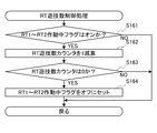
次に、図39を参照して、RT遊技数制御処理について説明する。はじめに、メインCPU31は、RT1作動中フラグ〜RT2作動中フラグの何れかがオンであるか否かを判別する(S161)。
[RT game number control processing]
Next, the RT game number control process will be described with reference to FIG. First, the
メインCPU31は、RT1作動中フラグ〜RT2作動中フラグの何れかがオンであると判別したときには、RT遊技数カウンタを1減算する(S162)。次に、メインCPU31は、RT遊技数カウンタが0であるか否かを判別する。メインCPU31は、RT遊技数カウンタが0であると判別したときには、RT1作動中フラグ〜RT2作動中フラグをオフにセットする(S164)。この処理が終了すると、RT遊技数カウンタ更新処理を終了する。
When the
[メインCPUの制御による割込処理(1.1173msec)]
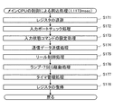
次に、図40を参照して、メインCPU31の制御による割込処理(1.1173msec)について説明する。はじめに、メインCPU31は、レジスタの退避を行う(S171)。次に、メインCPU31は、入力ポートチェック処理を行う(S172)。この処理では、ストップスイッチ7S等の各種スイッチから入力される信号がチェックされる。
[Interrupt processing under the control of the main CPU (1.1173 msec)]
Next, an interrupt process (1.1173 msec) controlled by the
次に、メインCPU31は、入力状態コマンドの設定処理を行う(S173)。この処理では、スタートレバー6やベットボタン11等のうち、どのような入力がなされたかのチェックを行う。次に、メインCPU31は、入力状態コマンド等を副制御回路72に送信する通信データ送信処理を行う(S174)。
Next, the
次に、メインCPU31は、リール制御処理を行う(S175)。この処理では、全リール3L,3C,3Rの回転開始が要求されたときに、各リール3L,3C,3Rの回転を開始し、その後一定速度での回転を行うよう、ステッピングモータ49L,49C,49Rの駆動が制御される。また、滑り駒数が決定されたときは、該当リールの回転が滑り駒数分継続するのを待ってその回転の減速及び停止を行うよう、ステッピングモータの駆動が制御される。
Next, the
次に、メインCPU31は、ランプ・7SEG駆動処理を行う(S176)。次に、メインCPU31は、タイマ管理処理を行う(S177)。次に、メインCPU31は、レジスタの復帰を行う(S178)。この処理が終了すると、割込処理を終了する。
Next, the
[副制御回路のサブCPUによって実行されるプログラムフロー]
主制御回路71のメインCPU31により実行されるプログラムの内容についての説明は以上である。次に、図41〜図52を参照して、副制御回路72のサブCPU81により実行されるプログラムの内容について説明する。
[Program flow executed by sub CPU of sub control circuit]
This completes the description of the contents of the program executed by the
[電源投入]
図41を参照して、電源投入時の副制御回路70の動作について説明する。
[Power on]
With reference to FIG. 41, the operation of the
電源が投入されると、初めに、サブCPU81は、初期化処理を行い(S301)、S302に移る。この処理では、サブCPU81は、SDRAM73、描画用SDRAM75などのエラーチェック、タスクシステムの初期化を行う。タスクシステムは、タイマ割込同期のタスクグループであるランプ制御タスク及びサウンド制御タスクと、主にVSYNC(垂直同期信号)割込同期のタスクグループであるマザータスクとを含んで構成される。
When the power is turned on, first, the
サブCPU81は、S302では、ランプ制御タスクを起動し、S303に移る。ランプ制御タスクは、サブCPU81に対して2ms毎に送信されるタイマ割込イベントメッセージをサブCPU81が受け取るのを待ち、このタイマ割込イベントメッセージをサブCPU81が受け取ったことに応じて、サブCPU81は、LED類101などの点灯状態を制御する処理を行う。そして、同じタイマ割込同期のタスクグループであるサウンド制御タスクに移る。
In S302, the
サブCPU81は、S303では、サウンド制御タスクを起動し、S304に移る。サウンド制御タスクは、サブCPU81は、スピーカ21L,21Rからの出音状態を制御する処理を行い、同じタイマ割込同期のタスクグループである振動装置制御タスクに移る。
In S303, the
サブCPU81は、S304では、振動装置制御タスクを起動し、S305に移る。振動装置制御タスクは、サブCPU81は、振動データ(図28参照)に基づいてスタートレバー6の振動を制御する処理を行い、同じタイマ割込同期のタスクグループであるランプ制御タスクに移る。
In S304, the
サブCPU81は、S305では、マザータスクを起動して処理を打ち切る。マザータスクについては、図42を参照して説明する。
In S305, the
[マザータスク]
次に、図42を参照して、マザータスクについて説明する。
[Mother Task]
Next, the mother task will be described with reference to FIG.
初めに、サブCPU81は、描画タスクを起動し(S311)、S312に移る。描画タスクでは、サブCPU81に対して1000/30ms毎に送信されるVSYNC割込信号をサブCPU81が受け取るのを待ち、このVSYNC割込信号をサブCPU81が受け取ったことに応じて、サブCPU81は、液晶表示装置131での表示状態を制御する処理を行う。
First, the
サブCPU81は、S312では、主基板通信タスクを起動し、S313に移る。主基板通信タスクについては、後に図46を参照して説明するが、主制御回路60に設けられたメインCPU31からサブCPU81に対して送信される各種のコマンドをサブCPU81が受け取るのを待ち、これら各種のコマンドをサブCPU81が受け取ったことに応じて、サブCPU81は、受け取ったコマンドに応じた処理を行う。例えば、メインCPU31からスタートコマンドを受信したときには、サブCPU81は、スタートコマンド受信時処理を行い、メインCPU31からリール停止コマンドを受信したときには、サブCPU81は、リール停止コマンド受信時処理を行う。
In step S312, the
サブCPU81は、S313では、VSYNC割込同期のタスクグループの「描画タスク」を実行し、S313に移る。
In step S313, the
[ランプ制御タスク]
次に、図43を参照して、ランプ制御タスクについて説明する。
[Ramp control task]
Next, the lamp control task will be described with reference to FIG.
初めに、サブCPU81は、ランプ関連データの初期化処理をし(S321)、S322に移る。次に、サブCPU81は、2msイベント待ち処理を実行し、S323に移る。
First, the
次に、サブCPU81は、S323では、同一グループ(タイマ割込同期のタスクグループ)の次のタスク「サウンド制御タスク」を実行する。この処理では、サブCPU81は、図44で説明するサウンド制御タスクへ処理をジャンプさせる。
Next, in S323, the
サブCPU81は、S324では、ランプデータをランプ格納領域から取り出し、S325に移る。この処理は、図45で説明する振動装置制御タスクから処理がジャンプしてきたときに行われる。
In step S324, the
次に、サブCPU81は、S325では、ランプデータの解析処理を行い、S326へ移る。サブCPU81は、S326では、ランプ点灯制御処理を行い、S322へ移る。
Next, in step S325, the
[サウンド制御タスク]
次に、図44を参照して、サウンド制御タスクについて説明する。
Sound control task
Next, a sound control task will be described with reference to FIG.
初めに、サブCPU81は、サウンド関連データの初期化処理をし(S331)、S332に移る。
First, the
次に、サブCPU81は、S332では、同一グループ(タイマ割込同期のタスクグループ)の次のタスク「振動装置制御タスク」を実行する。この処理では、サブCPU81は、図45で説明する振動装置制御タスクへ処理をジャンプさせる。
Next, in S332, the
サブCPU81は、S333では、サウンドデータをサウンド格納領域から取り出し、S334に移る。この処理は、図43で説明したランプ制御タスクから処理がジャンプしてきたときに行われる。
In step S333, the
次に、サブCPU81は、S334では、サウンドデータの解析処理を行い、S335へ移る。サブCPU81は、S335では、サウンド出力制御処理を行い、S332へ移る。
Next, in step S334, the
[振動装置制御タスク]
次に、図45を参照して、振動装置制御タスクについて説明する。
[Vibration device control task]
Next, the vibration device control task will be described with reference to FIG.
初めに、サブCPU81は、振動関連データの初期化処理をし(S341)、S342に移る。
First, the
次に、サブCPU81は、S342では、同一グループ(タイマ割込同期のタスクグループ)の次のタスク「ランプ制御タスク」を実行する。この処理では、サブCPU81は、図43で説明したランプ制御タスクへ処理をジャンプさせる。
Next, in S342, the
サブCPU81は、S343では、振動データを振動格納領域から取り出し、S344に移る。この処理は、図44で説明したサウンド制御タスクから処理がジャンプしてきたときに行われる。
In step S343, the
次に、サブCPU81は、S344では、振動データの解析処理を行い、S345へ移る。サブCPU81は、S345では、振動制御処理を行い、S342へ移る。
Next, in step S344, the
[主基板通信制御タスク]
次に、図46を参照して、主基板通信タスクについて説明する。
[Main board communication control task]
Next, the main board communication task will be described with reference to FIG.
初めに、サブCPU81は、送信メッセンジャーキューの初期化を行い(S351)、S352に移る。サブCPU81は、S352では、コマンド受信のチェックを行い、ステップS353に移る。サブCPU81は、S353では、前回とは異なるコマンドを受信したか否かを判別する。前回とは異なるコマンドを受信したと判別した場合には、S354に移り、前回とは異なるコマンドを受信しないと判別した場合には、S352に移る。
First, the
サブCPU81は、S354では、受信したコマンドのパラメータから内部当籤役、遊技状態、設定値、RTゲーム数カウンタの値などの遊技情報を作成し、S355に移る。サブCPU81は、S355では、作成した遊技情報をゲームデータ記憶領域に格納し、S356に移る。サブCPU81は、S356では、図47を参照して説明するコマンド解析処理を行い、S352に移る。
In S354, the
[コマンド解析処理]
次に、図47を参照して、コマンド解析処理について説明する。
[Command analysis processing]
Next, command analysis processing will be described with reference to FIG.
初めに、サブCPU81は、図48を参照して説明する演出内容決定処理を行い(S361)、S362に移る。次に、サブCPU81は、S362では、ランプデータの決定及び格納処理を行い、S363に移る。次に、サブCPU81は、S363では、サウンドデータの決定及び格納処理を行い、S352に移る。
First, the
[演出内容決定処理]
次に、図48を参照して、演出内容決定処理について説明する。
[Production content decision processing]
Next, the effect content determination process will be described with reference to FIG.
初めに、サブCPU81は、メダル投入コマンド受信時であるか否かを判別する(S371)。このとき、メダル投入コマンド受信時である場合には、次いで、メダル投入コマンド受信時処理を行い(S372)、演出内容決定処理を終了する。
First, the
他方、メダル投入コマンド受信時でない場合には、次いで、スタートコマンド受信時であるか否かを判別する(S373)。このとき、スタートコマンド受信時である場合には、次いで、後に図49を参照して説明するスタートコマンド受信時処理を行い(S374)、演出内容決定処理を終了する。 On the other hand, if it is not at the time of receiving a medal insertion command, it is then determined whether or not it is at the time of receiving a start command (S373). At this time, if it is at the time of receiving the start command, next, the process at the time of receiving the start command, which will be described later with reference to FIG.
他方、スタートコマンド受信時でない場合には、次いで、リール回転開始コマンド受信時であるか否かを判別する(S375)。このとき、リール回転開始コマンド受信時である場合には、次いで、後に図51を参照して説明するリール回転開始コマンド受信時処理を行い(S376)、演出内容決定処理を終了する。 On the other hand, if it is not at the time of receiving the start command, it is then determined whether or not it is at the time of receiving the reel rotation start command (S375). At this time, if it is time to receive a reel rotation start command, a reel rotation start command reception process described later with reference to FIG. 51 is performed (S376), and the effect content determination process ends.
他方、リール回転開始コマンド受信時でない場合には、次いで、リール停止コマンド受信時であるか否かを判別する(S377)。このとき、リール停止コマンド受信時である場合には、次いで、リール停止コマンド受信時処理を行い(ステップS378)、演出内容決定処理を終了する。リール停止コマンド受信時処理では、演出構成テーブル(図25)を参照し、登録されている演出番号に基づいて、リール停止時の演出データを登録する。 On the other hand, if it is not at the time of receiving the reel rotation start command, it is then determined whether or not it is at the time of receiving the reel stop command (S377). At this time, if it is time to receive a reel stop command, a reel stop command reception process is then performed (step S378), and the effect content determination process ends. In the reel stop command reception processing, the production data at the time of reel stop is registered based on the registered production number with reference to the production configuration table (FIG. 25).
他方、リール停止コマンド受信時でない場合には、次いで、表示コマンド受信時であるか否かを判別する(ステップS379)。このとき、表示コマンド受信時である場合には、次いで、表示コマンド受信時処理を行い(ステップS380)、演出内容決定処理を終了する。表示コマンド受信時処理では、演出構成テーブル(図25)を参照し、登録されている演出番号に基づいて、表示役成立時の演出データを登録する。なお、演出構成テーブル(図25)によれば、表示役成立時(表示コマンド受信時)の演出データは、演出番号にかかわらず、データ種別決定テーブル(図27)を参照することによってRT遊技状態に応じて決定され登録される。 On the other hand, if it is not at the time of receiving a reel stop command, it is then determined whether or not it is at the time of receiving a display command (step S379). At this time, if it is a display command reception time, a display command reception time process is then performed (step S380), and the effect content determination process is terminated. In the display command reception process, the effect composition table (FIG. 25) is referred to, and the effect data when the display combination is established is registered based on the registered effect number. According to the effect composition table (FIG. 25), the effect data at the time when the display combination is established (when the display command is received) can be obtained by referring to the data type determination table (FIG. 27) regardless of the effect number. It is decided and registered according to.
他方、表示コマンド受信時でない場合には、次いで、入力状態コマンド受信時であるか否かを判別する(ステップS381)。このとき、入力状態コマンド受信時である場合には、次いで、後に図52を参照して説明する入力状態コマンド受信時処理を行い(ステップS382)、演出内容決定処理を終了する。他方、入力状態コマンド受信時ではない場合には、次いで、受信したコマンドに対応する処理を実行し(ステップS383)、演出内容決定処理を終了する。 On the other hand, if the display command is not received, it is then determined whether or not the input state command is received (step S381). At this time, if it is at the time of receiving the input state command, next, an input state command receiving process described later with reference to FIG. 52 is performed (step S382), and the effect content determining process is ended. On the other hand, if it is not at the time of receiving the input state command, next, processing corresponding to the received command is executed (step S383), and the effect content determination processing is ended.
[スタートコマンド受信時処理]
次に、図49を参照して、スタートコマンド受信時処理について説明する。
[Start command reception processing]
Next, the start command reception process will be described with reference to FIG.
初めに、サブCPU81は、各種遊技数カウンタ更新処理を行い(S391)、次いで、後に図50を参照して説明する演出抽籤処理を実行する(S392)。
First, the
S392の処理が終わると、サブCPU81は、ウェイトタイマが500ms以上であるか否かを判断する(S393)。このウェイトタイマは、図51で説明するリール回転開始コマンド受信時処理でセット(初期値4000ms)される。よって、ウェイトタイマが500ms以上であるか否かを判断することは、前回遊技におけるリール回転開始からの経過時間が3500ms以内であるか否かを判断することである。サブCPU81は、ウェイトタイマが500ms以上であると判断した場合には、振動データの決定処理を行う(S394)。この処理は、振動態様抽籤テーブル(図28)を参照することにより行う。S394の処理が終わると、サブCPU81は、振動データを登録する(S395)。
When the processing of S392 is completed, the
S393において、ウェイトタイマが500ms以上ではないと判断した場合、又は、S395の処理が終わると、サブCPU81は、演出構成テーブル(図25)を参照し、登録されている演出番号に基づいて、開始操作時(スタートレバーオン時)の演出データを登録する(S396)。なお、演出構成テーブル(図25)によれば、開始操作時(スタートレバーオン時)の演出データは、演出番号にかかわらず、データ種別決定テーブル(図27)を参照することによってRT遊技状態に応じて決定され登録される。S396の処理が終了すると、サブCPU81は、スタートコマンド受信時処理を終了する。
In S393, when it is determined that the wait timer is not 500 ms or longer, or when the process of S395 is completed, the
[演出抽籤処理]
次に、図50を参照して、演出抽籤処理について説明する。
[Direction lottery processing]
Next, the effect lottery process will be described with reference to FIG.
初めに、サブCPU81は、演出選択用乱数値を取得して格納する(S401)。次にサブCPU81は、演出番号抽籤テーブル(変動開始時)(図29)を参照し、スタートコマンドのパラメータ(内部当籤役)と取得した演出選択用乱数値とに基づいて、演出番号を決定する(S402)。
First, the
次に、サブCPU81は、特定の演出番号(演出番号=4〜6)であるか否かを判別する(S403)。サブCPU81は、特定の演出番号(演出番号=4〜6)であると判別した場合には、演出ボタン有効フラグをオンにする(S404)。
Next, the
S403において、特定の演出番号(演出番号=4〜6)ではないと判断した場合、又は、S404の処理が終わると、サブCPU81は、決定した演出番号を登録する(S405)。
In S403, when it is determined that the effect number is not a specific effect number (effect number = 4 to 6), or when the process of S404 ends, the
[リール回転開始コマンド受信時処理]
次に、図51を参照して、リール回転開始コマンド受信時処理について説明する。
[Reel rotation start command reception processing]
Next, with reference to FIG. 51, the reel rotation start command reception process will be described.
初めに、サブCPU81は、ウェイトタイマを4000msにセットする(S411)。次に、サブCPU81は、演出構成テーブル(図25)を参照し、登録されている演出番号に基づいて、リール回転開始時(変動開始時)の演出データを登録する(S412)。S412の処理が終了すると、サブCPU81は、リール回転開始コマンド受信時処理を終了する。
First, the
[入力状態コマンド受信時処理]
次に、図51を参照して、入力状態コマンド受信時処理について説明する。
[Process when receiving input status command]
Next, with reference to FIG. 51, an input state command reception process will be described.
初めに、サブCPU81は、BETボタンの操作があったか否かを判別する(S421)。BETボタンの操作があったと判別した場合には、S422の処理を行う。BETボタンの操作がなかったと判別した場合には、サブCPU81は、入力状態コマンド受信時処理を終了する。
First, the
サブCPU81は、S422で、演出ボタン有効フラグがオンか否かを判別する。演出ボタン有効フラグがオンと判別した場合には、S423の処理を行う。演出ボタン有効フラグがオンではないと判別した場合には、サブCPU81は、入力状態コマンド受信時処理を終了する。
In step S422, the
サブCPU81は、S423で、演出ボタン有効フラグをオフにする。次に、サブCPU81は、S424で、演出データの決定処理を行う。この処理では、演出番号抽籤テーブル(ボタン検知あり)(図30)を参照し、内部当籤役と演出選択用乱数値とに基づいて、演出番号を決定する。
In step S423, the
S424の処理が終わると、サブCPU81は、S425で、演出データの更新処理を行う。この処理では、登録されている演出データを更新する。S425の処理が終了すると、サブCPU81は、入力状態コマンド受信時処理を終了する。
When the processing of S424 ends, the
以上、本発明の実施例によれば、サブCPU81は、リール3L,3C,3Rの回転開始が許可されていないことを条件に、スタートレバー6を振動させる振動モータ610を駆動させる制御を行う。このことにより、振動モータ610を駆動することによるスタートレバーの振動によってリール3L,3C,3Rの回転が開始されることはないので、振動モータ610によるスタートレバー6の振動によってリール3L,3C,3Rの回転が開始されるという誤作動をなくすとともに、演出の多様化を図り遊技の興趣の向上を図ることができる。
As described above, according to the embodiment of the present invention, the
また、本発明の実施例によれば、サブCPU81は、有効にされている機能制御手段に基づいて、発光色を決定し、発光体284を発光させる。また、この発光体284は、ボタンカバー210に描かれた各文字と同系色の光を照射する。これにより、ベットボタン11に複数の機能を設けた場合であっても、発光体284の発光色により視認できる文字を「MAX」又は「CHANCE」のいずれかに変化させることができるので、機能に合わせて文字を変化させることができる。したがって、ベットボタン11で複数の機能を有しつつも、遊技者がベットボタン11の機能を把握できることができ、演出専用のボタンを他の操作ボタンと兼用させることにより、コストアップ、配置スペースの制約の問題を解消させることができる。
Further, according to the embodiment of the present invention, the
以上、実施例について説明したが、本発明はこれに限られるものではない。 As mentioned above, although the Example was described, this invention is not limited to this.
上述の実施の形態では、ウェイト時間が経過するまでの間に振動モータ610によるスタートレバー6の振動を制御しているが、これに限られない。例えば、遊技待機中(デモ画面表示中)や、ロック期間中(スタートレバーの操作を受け付けない期間中)でもよい。
In the above-described embodiment, the vibration of the
上述の実施の形態では、ベットボタン11に複数の機能を備えさせ、ベットボタン11の発光を制御しているがこれに限られない。清算ボタン12や、ストップボタン7L,7C,7R等に複数の機能を備えさせ、機能に応じて発光を制御してもよい。
In the above-described embodiment, the
1 パチスロ
3L,3C,3R リール
6 スタートレバー
7L,7C,7R 停止ボタン
30 マイクロコンピュータ
31 メインCPU
32 メインROM
33 メインRAM
71 主制御回路
1
32 Main ROM
33 Main RAM
71 Main control circuit
Claims (3)
遊技者が操作可能なスタートレバーと、
前記スタートレバーの操作に応じて、単位遊技の開始を指令する遊技開始指令信号を出力する遊技開始指令手段と、
所定条件の成立により、前記図柄表示手段により表示される図柄の変動の開始を許可する変動開始許可手段と、
前記遊技開始指令手段により遊技開始指令信号を出力されること及び前記変動開始許可手段により変動の開始が許可されることを条件に、前記図柄表示手段により表示される図柄の変動を開始させる制御を行う図柄変動開始制御手段と、
前記スタートレバーを振動させる振動装置と、
前記変動開始許可手段により変動の開始が許可されていないことを条件に、前記振動装置を振動させる制御を行う振動装置制御手段と、を備えることを特徴とする遊技機。 A symbol display means having a plurality of display units for displaying a plurality of types of symbols;
A start lever that can be operated by the player;
A game start command means for outputting a game start command signal for commanding the start of a unit game in response to an operation of the start lever;
Fluctuation start permission means for permitting the start of the fluctuation of the symbol displayed by the symbol display means when the predetermined condition is satisfied;
Control for starting the change of the symbol displayed by the symbol display means on condition that the game start command signal is output by the game start command means and the start of change is permitted by the change start permission means. A symbol variation start control means to perform;
A vibration device for vibrating the start lever;
A gaming machine comprising: vibration device control means for performing control to vibrate the vibration device on condition that the start of variation is not permitted by the variation start permission means.
時間を計測する時間計測手段を更に備え、
前記変動開始許可手段は、前記時間計測手段によって所定の時間が計測されたことを条件に、前記図柄表示手段により表示される図柄の変動の開始を許可することを特徴とする遊技機。 In the gaming machine according to claim 1,
It further comprises time measuring means for measuring time,
The game machine according to claim 1, wherein the change start permission means permits the start of the change of the symbol displayed by the symbol display means on the condition that a predetermined time is measured by the time measurement means.
前記遊技開始指令信号に応じて、予め定められた複数の役から当籤役を決定する内部当籤役決定手段と、
前記内部当籤役決定手段によって決定された内部当籤役に基づいて、複数種類の振動態様の中から一の振動態様を決定する振動態様決定手段と、を更に備え、
前記振動装置制御手段は、前記振動態様決定手段によって決定された振動態様に基づいて、前記振動装置を駆動させる制御を行うことを特徴とする遊技機。 In the gaming machine according to claim 1 or 2,
An internal winning combination determining means for determining a winning combination from a plurality of predetermined combinations in response to the game start command signal;
Vibration mode determining means for determining one vibration mode from a plurality of types of vibration modes based on the internal winning combination determined by the internal winning combination determining means,
The gaming machine control unit performs control for driving the vibration unit based on the vibration mode determined by the vibration mode determination unit.
Priority Applications (1)
| Application Number | Priority Date | Filing Date | Title |
|---|---|---|---|
| JP2008209052A JP5468752B2 (en) | 2008-08-14 | 2008-08-14 | Game machine |
Applications Claiming Priority (1)
| Application Number | Priority Date | Filing Date | Title |
|---|---|---|---|
| JP2008209052A JP5468752B2 (en) | 2008-08-14 | 2008-08-14 | Game machine |
Publications (2)
| Publication Number | Publication Date |
|---|---|
| JP2010042167A true JP2010042167A (en) | 2010-02-25 |
| JP5468752B2 JP5468752B2 (en) | 2014-04-09 |
Family
ID=42014046
Family Applications (1)
| Application Number | Title | Priority Date | Filing Date |
|---|---|---|---|
| JP2008209052A Expired - Fee Related JP5468752B2 (en) | 2008-08-14 | 2008-08-14 | Game machine |
Country Status (1)
| Country | Link |
|---|---|
| JP (1) | JP5468752B2 (en) |
Cited By (2)
| Publication number | Priority date | Publication date | Assignee | Title |
|---|---|---|---|---|
| JP2015080661A (en) * | 2013-10-24 | 2015-04-27 | 株式会社北電子 | Game machine |
| JP2017196141A (en) * | 2016-04-27 | 2017-11-02 | 株式会社三共 | Slot machine |
Citations (6)
| Publication number | Priority date | Publication date | Assignee | Title |
|---|---|---|---|---|
| JP2000005375A (en) * | 1998-06-19 | 2000-01-11 | Takasago Electric Ind Co Ltd | Slot machine |
| JP2000210409A (en) * | 1999-01-21 | 2000-08-02 | Kyowa Denshi Kogyo Kk | Slot machine |
| JP2001095976A (en) * | 1999-09-30 | 2001-04-10 | Daito Giken:Kk | Game machine, game method, and recording medium for game method |
| JP2005334076A (en) * | 2004-05-24 | 2005-12-08 | Aruze Corp | Game machine |
| JP2006042870A (en) * | 2004-07-30 | 2006-02-16 | Aruze Corp | Game machine |
| JP2006230807A (en) * | 2005-02-25 | 2006-09-07 | Olympia:Kk | Game machine, program and recording medium |
-
2008
- 2008-08-14 JP JP2008209052A patent/JP5468752B2/en not_active Expired - Fee Related
Patent Citations (6)
| Publication number | Priority date | Publication date | Assignee | Title |
|---|---|---|---|---|
| JP2000005375A (en) * | 1998-06-19 | 2000-01-11 | Takasago Electric Ind Co Ltd | Slot machine |
| JP2000210409A (en) * | 1999-01-21 | 2000-08-02 | Kyowa Denshi Kogyo Kk | Slot machine |
| JP2001095976A (en) * | 1999-09-30 | 2001-04-10 | Daito Giken:Kk | Game machine, game method, and recording medium for game method |
| JP2005334076A (en) * | 2004-05-24 | 2005-12-08 | Aruze Corp | Game machine |
| JP2006042870A (en) * | 2004-07-30 | 2006-02-16 | Aruze Corp | Game machine |
| JP2006230807A (en) * | 2005-02-25 | 2006-09-07 | Olympia:Kk | Game machine, program and recording medium |
Cited By (2)
| Publication number | Priority date | Publication date | Assignee | Title |
|---|---|---|---|---|
| JP2015080661A (en) * | 2013-10-24 | 2015-04-27 | 株式会社北電子 | Game machine |
| JP2017196141A (en) * | 2016-04-27 | 2017-11-02 | 株式会社三共 | Slot machine |
Also Published As
| Publication number | Publication date |
|---|---|
| JP5468752B2 (en) | 2014-04-09 |
Similar Documents
| Publication | Publication Date | Title |
|---|---|---|
| JP2009285267A (en) | Game machine | |
| JP5350680B2 (en) | Game machine | |
| JP5430896B2 (en) | Game machine | |
| JP2011234927A (en) | Game machine | |
| JP5468752B2 (en) | Game machine | |
| JP5463028B2 (en) | Game machine | |
| JP6154932B2 (en) | Game machine | |
| JP5903484B2 (en) | Game machine | |
| JP5775137B2 (en) | Game machine | |
| JP2009285199A (en) | Game machine | |
| JP5475275B2 (en) | Game machine | |
| JP2010075479A (en) | Game machine | |
| JP6580745B2 (en) | Game machine | |
| JP2009285268A (en) | Game machine | |
| JP6138207B2 (en) | Game machine | |
| JP5785279B2 (en) | Game machine | |
| JP2010082024A (en) | Game machine | |
| JP2009285069A (en) | Game machine | |
| JP2009261601A (en) | Game machine | |
| JP2010051519A (en) | Game machine | |
| JP2010051452A (en) | Game machine | |
| JP2019055274A (en) | Game machine | |
| JP2010029417A (en) | Game machine | |
| JP2009261602A (en) | Game machine | |
| JP2018020228A (en) | Game machine |
Legal Events
| Date | Code | Title | Description |
|---|---|---|---|
| RD02 | Notification of acceptance of power of attorney |
Free format text: JAPANESE INTERMEDIATE CODE: A7422 Effective date: 20110415 |
|
| RD04 | Notification of resignation of power of attorney |
Free format text: JAPANESE INTERMEDIATE CODE: A7424 Effective date: 20110421 |
|
| A621 | Written request for application examination |
Free format text: JAPANESE INTERMEDIATE CODE: A621 Effective date: 20110622 |
|
| A977 | Report on retrieval |
Free format text: JAPANESE INTERMEDIATE CODE: A971007 Effective date: 20130123 |
|
| A131 | Notification of reasons for refusal |
Free format text: JAPANESE INTERMEDIATE CODE: A131 Effective date: 20130129 |
|
| A521 | Written amendment |
Free format text: JAPANESE INTERMEDIATE CODE: A523 Effective date: 20130326 |
|
| RD02 | Notification of acceptance of power of attorney |
Free format text: JAPANESE INTERMEDIATE CODE: A7422 Effective date: 20130326 |
|
| A131 | Notification of reasons for refusal |
Free format text: JAPANESE INTERMEDIATE CODE: A131 Effective date: 20131112 |
|
| A521 | Written amendment |
Free format text: JAPANESE INTERMEDIATE CODE: A523 Effective date: 20131225 |
|
| TRDD | Decision of grant or rejection written | ||
| A01 | Written decision to grant a patent or to grant a registration (utility model) |
Free format text: JAPANESE INTERMEDIATE CODE: A01 Effective date: 20140128 |
|
| A61 | First payment of annual fees (during grant procedure) |
Free format text: JAPANESE INTERMEDIATE CODE: A61 Effective date: 20140130 |
|
| R150 | Certificate of patent or registration of utility model |
Ref document number: 5468752 Country of ref document: JP Free format text: JAPANESE INTERMEDIATE CODE: R150 Free format text: JAPANESE INTERMEDIATE CODE: R150 |
|
| RD04 | Notification of resignation of power of attorney |
Free format text: JAPANESE INTERMEDIATE CODE: R3D04 |
|
| R250 | Receipt of annual fees |
Free format text: JAPANESE INTERMEDIATE CODE: R250 |
|
| R250 | Receipt of annual fees |
Free format text: JAPANESE INTERMEDIATE CODE: R250 |
|
| LAPS | Cancellation because of no payment of annual fees |