JP2010038432A - Air conditioning system and control method of air-conditioning system - Google Patents
Air conditioning system and control method of air-conditioning system Download PDFInfo
- Publication number
- JP2010038432A JP2010038432A JP2008201081A JP2008201081A JP2010038432A JP 2010038432 A JP2010038432 A JP 2010038432A JP 2008201081 A JP2008201081 A JP 2008201081A JP 2008201081 A JP2008201081 A JP 2008201081A JP 2010038432 A JP2010038432 A JP 2010038432A
- Authority
- JP
- Japan
- Prior art keywords
- air
- air conditioning
- conditioning system
- evaporator
- refrigerant
- Prior art date
- Legal status (The legal status is an assumption and is not a legal conclusion. Google has not performed a legal analysis and makes no representation as to the accuracy of the status listed.)
- Granted
Links
Images


Landscapes
- Air-Conditioning For Vehicles (AREA)
- Air Conditioning Control Device (AREA)
Abstract
Description
本発明は、例えば、車両に用いられる空調システム及び空調システムの制御方法に関する。 The present invention relates to an air conditioning system used for a vehicle and a method for controlling the air conditioning system, for example.
特許文献1に「車両用空調装置」が記載されている。 Patent Document 1 describes “vehicle air conditioner”.
この車両用空調装置は、蒸発器を空調機能と除湿機能に共用しており、蒸発器を通過する空気の状態に応じて装置の起動時間を制御することによって蒸発器を常に凝縮水で濡れた状態に保ち、異臭の発生を防いでいる。
空調に用いられる蒸発器には、除湿中に空気中の水分が凝縮し、この凝縮水に臭いを発生する成分が溶け込み、その後、蒸発器が乾燥モードに入ると、溶け込んだ臭い成分が放出されて車室内に悪臭が漂い、乗員に不快感を与えることがある。 In evaporators used for air conditioning, moisture in the air condenses during dehumidification, and components that generate odor dissolve in this condensed water, and then when the evaporator enters the drying mode, the dissolved odor components are released. This can cause a bad smell in the passenger compartment and cause discomfort to the passengers.
特許文献1の車両用空調装置は、悪臭の発生を防止しているが、熱交換器(蒸発器)のフィンには常に凝縮水が付着しており、付着した凝縮水が大きな通気抵抗になるから、熱交換率を向上させることが難しく、また、フィンのピッチを充分に狭くし、コンパクトにすることが難しい。 Although the vehicle air conditioner of Patent Document 1 prevents the generation of bad odor, condensed water always adheres to the fins of the heat exchanger (evaporator), and the attached condensed water becomes a large ventilation resistance. Therefore, it is difficult to improve the heat exchange rate, and it is difficult to make the fin pitch sufficiently narrow and compact.
また、蒸発器を常に凝縮水で濡れた状態に保つために、運転条件に制約を受けている。 In addition, operating conditions are limited in order to keep the evaporator always wet with condensed water.
そこで、この発明は、悪臭の発生を防止しながら、蒸発器を高性能にし、コンパクトにする空調システム及び空調システムの制御方法の提供を目的としている。 Accordingly, an object of the present invention is to provide an air conditioning system and a control method for the air conditioning system that make the evaporator high performance and compact while preventing the generation of malodor.
なお、本発明において、空調用空気とは、蒸発器を通過する熱交換空気のことであり、例えば、車両用の空調システムであれば、内気(車室内の空気)と外気(車室の外部から取り入れる空気)の両方を意味している。 In the present invention, the air-conditioning air is heat exchange air that passes through the evaporator. For example, in the case of a vehicle air-conditioning system, the inside air (air in the vehicle compartment) and the outside air (outside the vehicle compartment). Means both air taken in from).
請求項1の空調システムは、冷媒を圧縮する圧縮機と、圧縮された冷媒を放熱させて凝縮する凝縮器と、前記凝縮器からの冷媒を膨張させる膨張弁と、前記膨張弁からの冷媒と空調用空気とを熱交換する空調用蒸発器と、前記空調用蒸発器の表面温度を常に露点以上に保つコントローラとを有する空気調和装置と、前記空調用空気を除湿する除湿手段とを備えていることを特徴とする。 The air conditioning system of claim 1 includes a compressor that compresses the refrigerant, a condenser that dissipates and condenses the compressed refrigerant, an expansion valve that expands the refrigerant from the condenser, and a refrigerant from the expansion valve. An air conditioning evaporator that exchanges heat with air conditioning air; an air conditioner that includes a controller that always maintains a surface temperature of the air conditioning evaporator above a dew point; and a dehumidifying means that dehumidifies the air conditioning air. It is characterized by being.
請求項2の発明は、請求項1に記載された空調システムであって、前記空調用蒸発器に熱交換空気を送るブロワーを有し、前記コントローラが、前記ブロワーの風量と前記圧縮機の冷媒吐出量の少なくとも一方を制御することによって前記空調用蒸発器の表面温度を常に露点以上に保つことを特徴とする。
Invention of
請求項3の発明は、請求項1に記載された空調システムであって、前記コントローラが、前記膨張弁の開度と前記圧縮機の冷媒吐出量の少なくとも一方を制御することによって前記空調用蒸発器の表面温度を常に露点以上に保つことを特徴とする。 A third aspect of the present invention is the air conditioning system according to the first aspect, wherein the controller controls at least one of an opening degree of the expansion valve and a refrigerant discharge amount of the compressor to evaporate the air conditioning. The surface temperature of the vessel is always kept above the dew point.
請求項4の発明は、請求項1〜請求項3のいずれかに記載された空調システムであって、前記除湿手段が、冷媒を圧縮する圧縮機と、圧縮された冷媒を放熱させて凝縮する凝縮器と、前記凝縮器からの冷媒を膨張させる膨張弁と、前記膨張弁からの冷媒と前記空調用空気とを熱交換する除湿用蒸発器と、前記除湿用蒸発器の表面温度を常に露点以下に保つコントローラとを備えていることを特徴とする。 Invention of Claim 4 is an air-conditioning system described in any one of Claims 1-3, Comprising: The said dehumidification means heat-dissipates and condenses the compressor which compressed the refrigerant | coolant, and the compressed refrigerant | coolant. The dew point is always the surface temperature of the condenser, the expansion valve that expands the refrigerant from the condenser, the dehumidifying evaporator that exchanges heat between the refrigerant from the expansion valve and the air-conditioning air, and the dehumidifying evaporator. And a controller that maintains the following.
請求項5の発明は、請求項1〜請求項3のいずれかに記載された発明であって、前記除湿手段が、吸着剤によって前記空調用空気から水分を吸着し、除湿するように構成されていることを特徴とする。
Invention of
請求項6の発明は、請求項1〜請求項3のいずれかに記載された発明であって、前記除湿手段と前記空気調和装置とが、同一の筐体にユニット化されており、前記空気調和装置と前記除湿手段が、空調用空気の流れの方向にこの順序で直列に配置され、前記空調用空気が、前記空気調和装置で空調された後、前記除湿手段で除湿されて室内に供給されることを特徴とする。 A sixth aspect of the invention is the invention according to any one of the first to third aspects, wherein the dehumidifying means and the air conditioner are unitized in the same casing, and the air The conditioning device and the dehumidifying means are arranged in series in this order in the flow direction of the air conditioning air, and after the air conditioning air is air-conditioned by the air conditioning device, it is dehumidified by the dehumidifying device and supplied indoors It is characterized by being.
請求項7の発明は、請求項1〜請求項3のいずれかに記載された空調システムであって、前記除湿手段と前記空気調和装置とが、同一の筐体にユニット化されており、前記空気調和装置と前記除湿手段が、空調用空気の流れの方向に並列配置され、前記空気調和装置によって空調された前記空調用空気と、前記除湿手段によって除湿された前記空調用空気とが混合された後室内に供給されることを特徴とする。
The invention of
請求項8の発明は、請求項1〜請求項3のいずれかに記載された空調システムであって、前記除湿手段と前記空気調和装置とが、互いに異なった筐体に収容されており、前記空気調和装置と前記除湿手段が、空調用空気の流れの方向に並列配置され、前記空気調和装置によって空調された前記空調用空気と、前記除湿手段によって除湿された前記空調用空気とが混合された後室内に供給されることを特徴とする。 The invention of claim 8 is the air conditioning system according to any one of claims 1 to 3, wherein the dehumidifying means and the air conditioner are housed in different housings, The air conditioning apparatus and the dehumidifying means are arranged in parallel in the flow direction of the air conditioning air, and the air conditioning air conditioned by the air conditioning apparatus and the air conditioning air dehumidified by the dehumidifying means are mixed. After that, it is supplied into the room.
請求項9に記載された空調システムの制御方法は、冷媒を圧縮する圧縮機と、圧縮された冷媒を放熱させて凝縮する凝縮器と、前記凝縮器からの冷媒を膨張させる膨張弁と、前記膨張弁からの冷媒と空調用空気とを熱交換する空調用蒸発器と、前記空調用空気を除湿する除湿手段とを備えた空調システムの制御方法であって、前記空調用蒸発器の表面温度が常に露点以上に保たれるように制御することを特徴とする空調システムの制御方法。
The control method of the air conditioning system according to
請求項10の発明は、請求項9に記載された空調システムの制御方法であって、前記空調用蒸発器に熱交換空気を送るブロワーの風量と前記圧縮機の冷媒吐出量の少なくとも一方を制御することによって前記空調用蒸発器の表面温度を常に露点以上に保つことを特徴とする。 A tenth aspect of the invention is a control method for an air conditioning system according to the ninth aspect, wherein at least one of an air volume of a blower for sending heat exchange air to the air conditioning evaporator and a refrigerant discharge amount of the compressor is controlled. By doing so, the surface temperature of the air conditioning evaporator is always kept above the dew point.
請求項11の発明は、請求項9に記載された空調システムの制御方法であって、前記膨張弁の開度と前記圧縮機の冷媒吐出量の少なくとも一方を制御することによって前記空調用蒸発器の表面温度を常に露点以上に保つことを特徴とする。
The invention of
請求項12の発明は、請求項9〜請求項11のいずれかに記載された空調システムの制御方法であって、前記除湿手段が、冷媒を圧縮する圧縮機と、圧縮された冷媒を放熱させて凝縮する凝縮器と、前記凝縮器からの冷媒を膨張させる膨張弁と、前記膨張弁からの冷媒と前記空調用空気とを熱交換する除湿用蒸発器とを備えており、前記除湿用蒸発器が常に露点以下に保たれるように制御することを特徴とする空調システムの制御方法。
The invention of claim 12 is the air conditioning system control method according to any one of
請求項13の発明は、請求項9〜請求項11のいずれかに記載された発明であって、記除湿手段が、吸着剤によって前記空調用空気から水分を吸着し、除湿するように構成されていることを特徴とする。 A thirteenth aspect of the present invention is the invention according to any one of the ninth to eleventh aspects, wherein the dehumidifying means adsorbs moisture from the air-conditioning air by an adsorbent and dehumidifies. It is characterized by.
請求項1の空調システムでは、空調用蒸発器が常に露点以上に保持され、フィンに水分が凝縮することがない上に、除湿手段を併用することによって空調用蒸発器は常に乾燥した状態の空調用空気を扱うことができるから、においの発生を抑えることが出来る。また、吹き出し温度の制限から開放されるため、吹き出し温度を露点より高くすることが可能となり、吹き出し温度を上げる事で温水ヒーターなどで再加熱することなく室内を快適に制御することができる。 In the air conditioning system according to claim 1, the air conditioning evaporator is always kept above the dew point, moisture is not condensed on the fins, and the air conditioning evaporator is always in a dry state by using dehumidifying means together. Because it can handle the working air, it is possible to suppress the generation of odors. Further, since the restriction on the blowing temperature is released, the blowing temperature can be made higher than the dew point, and by raising the blowing temperature, the room can be comfortably controlled without reheating with a hot water heater or the like.
また、車両の空調システムに用いた場合、特に、夏季は熱負荷が大きく、狭い車室を強力に冷房する必要があり、それだけ乾燥し易いが、本発明の空調システムでは、上記のように空気調和装置の空調機能と除湿手段の除湿機能とを互いに分離して稼働させることによって精密な温度及び湿度の制御が可能になり、車室内を常に快適な状態に保つことができる。 Further, when used in an air conditioning system for a vehicle, especially in summer, the heat load is large, and it is necessary to strongly cool a narrow passenger compartment and it is easy to dry. However, in the air conditioning system of the present invention, the air By operating the air conditioning function of the conditioning apparatus and the dehumidifying function of the dehumidifying means separately from each other, precise temperature and humidity control can be performed, and the vehicle interior can be always kept in a comfortable state.
また、空調用蒸発器は、上記のようにフィンに凝縮水が付着しないから、凝縮水による通気抵抗から解放され、熱交換率が向上して高性能になると共に、フィンのピッチを充分に狭くすることができるから、空調システムをそれだけコンパクトに構成することが可能になる。 In addition, since the condensate does not adhere to the fins as described above, the air conditioning evaporator is freed from the ventilation resistance due to the condensate, improves the heat exchange rate, improves performance, and sufficiently narrows the fin pitch. Therefore, the air conditioning system can be made more compact.
また、冷房負荷が低いとき臭気の問題がないために蒸発器温度を高く設定する事ができるので、COP(成績係数:エネルギー効率)がそれだけ向上する。 Further, since there is no problem of odor when the cooling load is low, the evaporator temperature can be set high, so that the COP (coefficient of performance: energy efficiency) is improved accordingly.
また、除湿手段だけを優先的に稼働させれば、室温(車室温度)を大きく低下させずに除湿することができ、湿度及び空気温度の調整が容易になる。 Further, if only the dehumidifying means is operated preferentially, it is possible to dehumidify without greatly reducing the room temperature (vehicle compartment temperature), and the humidity and air temperature can be easily adjusted.
また、除湿が不要なときは、除湿手段を停止することによって消費動力を容易に低減することができる。 Further, when dehumidification is unnecessary, the power consumption can be easily reduced by stopping the dehumidifying means.
請求項2の空調システムは、コントローラが、空調用蒸発器に熱交換空気を送るブロワーの風量と圧縮機の冷媒吐出量の少なくとも一方を制御し、空調用蒸発器を常に露点以上に保つことによって請求項1と同等の効果が得られる。
In the air conditioning system of
請求項3の空調システムは、コントローラが、膨張弁の開度と圧縮機の冷媒吐出量の少なくとも一方を制御し、空調用蒸発器を常に露点以上に保つことによって請求項1と同等の効果が得られる。
In the air conditioning system of
請求項4の空調システムは、請求項1〜請求項3と同等の効果が得られる。 The air conditioning system of claim 4 can achieve the same effects as those of claims 1 to 3.
また、除湿手段(除湿用蒸発器)の通過空気は常に露点以下に保たれており、フィンが常に凝縮水で濡れた状態にあって乾くことがないから、除湿用蒸発器でも悪臭の発生が防止される。 In addition, the air passing through the dehumidifying means (dehumidifying evaporator) is always kept below the dew point, and the fins are always wet with condensed water and do not dry. Is prevented.
従って、除湿手段は、特許文献2の従来技術と異なり、臭いの発生を避けるために運転条件(制御)を制約されることがないから、最高の効率で稼働させることができる。
Therefore, unlike the prior art of
請求項5の空調システムは、請求項1〜請求項3と同等の効果が得られる。 The air conditioning system according to the fifth aspect can achieve the same effects as the first to third aspects.
また、吸着剤によって水分を吸着する吸着方式の除湿手段では凝縮水が発生しないから、悪臭の発生が防止される。 Further, since the condensed moisture is not generated in the adsorption type dehumidifying means that adsorbs moisture with the adsorbent, the generation of malodor is prevented.
また、吸着方式の除湿手段には、シルカゲルやゼオライトのような吸湿剤を用いたデシカント式の除湿手段があり、このデシカント式では、吸湿剤を再生する際に発生する廃熱を利用できるから、空調システム全体のエネルギー効率がそれだけ向上する。 In addition, the adsorption type dehumidifying means includes a desiccant type dehumidifying means using a hygroscopic agent such as silica gel or zeolite, and in this desiccant type, waste heat generated when regenerating the hygroscopic agent can be used. The energy efficiency of the entire air conditioning system is improved accordingly.
請求項6の空調システムは、除湿手段と空気調和装置とを同一の筐体でユニット化すると共に、空調用空気を空気調和装置で空調した後に、除湿手段で除湿することによって、請求項1〜請求項5の構成と同等の効果が得られる。 The air conditioning system of claim 6 comprises unitizing the dehumidifying means and the air conditioner in the same casing, and air-conditioning air by the air conditioner and then dehumidifying by the dehumidifying means. The same effect as that of the fifth aspect can be obtained.
また、この構成と反対に、空調用空気を除湿用蒸発器で除湿した後に空調用蒸発器で熱交換すると、除湿用蒸発器に凝縮した凝縮水が空調用蒸発器にも付着して悪臭を発生させる恐れがあるから、この構成のように、空気調和装置と除湿手段とを空調用空気の流れの方向に直列配置したことによって、除湿用蒸発器からの凝縮水が空調用蒸発器に付着することが避けられる。 Contrary to this configuration, if the air conditioning air is dehumidified with the dehumidifying evaporator and then heat exchange is performed with the air conditioning evaporator, the condensed water condensed in the dehumidifying evaporator will also adhere to the air conditioning evaporator and cause bad odor. Condensed water from the dehumidifying evaporator adheres to the air conditioning evaporator by arranging the air conditioning device and the dehumidifying means in series in the direction of the air conditioning air flow as in this configuration. Is avoided.
また、除湿手段と空気調和装置とを同一の筐体でユニットにしたこの空調システムは、それだけコンパクト化されるから、例えば、車両に搭載する場合は、車載性が向上する。 In addition, since this air conditioning system in which the dehumidifying means and the air conditioner are unitized in the same casing is made more compact, for example, when mounted on a vehicle, the in-vehicle performance is improved.
請求項7の空調システムは、除湿手段と空気調和装置とを同一の筐体でユニット化し、空気調和装置と除湿手段とを空調用空気の流れの方向に並列配置し、空気調和装置で空調された空調用空気と、除湿手段で除湿された空調用空気とを後で混合することによって、請求項1〜請求項5の構成と同等の効果が得られる。
In the air conditioning system of
また、除湿手段と空気調和装置とを同一の筐体でユニットにしたこの空調システムは、それだけコンパクト化されるから、例えば、車両に搭載する場合は、車載性が向上する。 In addition, since this air conditioning system in which the dehumidifying means and the air conditioner are unitized in the same casing is made more compact, for example, when mounted on a vehicle, the in-vehicle performance is improved.
請求項8の空調システムは、除湿手段と空気調和装置とが、互いに異なった筐体に収容されて別のユニットになっており、空気調和装置と除湿手段とを空調用空気の流れの方向に並列配置し、空気調和装置で空調された空調用空気と、除湿手段で除湿された空調用空気とを後で混合することによって、請求項1〜請求項5の構成と同等の効果が得られる。 In the air conditioning system of claim 8, the dehumidifying means and the air conditioner are housed in different housings to form separate units, and the air conditioner and the dehumidifying means are arranged in the direction of the air conditioning air flow. The effect equivalent to the structure of Claims 1-5 is acquired by mixing in parallel and the air-conditioning air air-conditioned with the air conditioning apparatus and the air-conditioning air dehumidified by the dehumidifying means afterwards. .
また、除湿手段と空気調和装置とを別のユニットで構成したことにより、既存の除湿専用装置を除湿手段として利用することができるから、最適な除湿手段をそれだけ広い範囲から選択することが可能になる。 In addition, since the dehumidifying means and the air conditioner are configured as separate units, the existing dehumidifying device can be used as the dehumidifying means, so that the optimum dehumidifying means can be selected from a wide range. Become.
請求項9に記載された空調システムの制御方法は、請求項1に記載された空調システムと同等の効果が得られる。
The control method of the air conditioning system described in
請求項10に記載された空調システムの制御方法は、請求項9の構成と同等の効果が得られる。 The air conditioning system control method according to the tenth aspect of the present invention can achieve the same effect as the ninth aspect.
請求項11に記載された空調システムの制御方法は、請求項9の構成と同等の効果が得られる。 The control method for the air conditioning system according to the eleventh aspect of the present invention can achieve the same effect as that of the ninth aspect.
請求項12に記載された空調システムの制御方法は、請求項9〜請求項11の構成と同等の効果が得られる。
The control method of the air conditioning system described in claim 12 can obtain the same effects as the configurations of
請求項13に記載された空調システムの制御方法は、請求項9〜請求項11の構成と同等の効果が得られる。
The control method of the air conditioning system described in
<第1実施形態>
図1を参照しながら本発明の空調システム1を説明する。図1は空調システム1の構成を示すブロック図である。
<First Embodiment>
An air conditioning system 1 of the present invention will be described with reference to FIG. FIG. 1 is a block diagram showing the configuration of the air conditioning system 1.
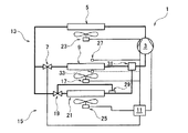
空調システム1は、冷媒を圧縮する圧縮機3と、圧縮された冷媒を放熱させて凝縮する凝縮器5と、凝縮器5からの冷媒を膨張させる膨張弁7と、膨張弁7からの冷媒と空調用空気とを熱交換する空調用蒸発器9と、空調用蒸発器9の表面温度を常に露点以上に保つコントローラ11とを有する空気調和装置13と、空調用空気を除湿する除湿手段15とを備えている。
The air conditioning system 1 includes a
また、空調用蒸発器9に熱交換空気(空調用空気)を送るブロワー17を有し、コントローラ11が、ブロワー17の風量と、圧縮機3の冷媒吐出量を制御することによって空調用蒸発器9の表面温度を常に露点以上に保持している。
Moreover, it has the
また、除湿手段15は、冷媒を圧縮する圧縮機3と、圧縮された冷媒を放熱させて凝縮する凝縮器5と、凝縮器5からの冷媒を膨張させる膨張弁19と、膨張弁19からの冷媒と空調用空気とを熱交換する除湿用蒸発器21と、除湿用蒸発器21の表面温度を常に露点以下に保つコントローラ11とを備えている。
The dehumidifying means 15 includes a
次に、空調システム1の構成を説明する。 Next, the configuration of the air conditioning system 1 will be described.
空調システム1は、車両用の空調システムであり、上記の構成要素に加えて、凝縮器5と除湿用蒸発器21をそれぞれ冷却するブロワー23,25と、空調用蒸発器9の出口側で空気の湿度を検知する出口側湿度センサー27と、除湿用蒸発器21の出口側で冷媒の温度を検知する冷媒温度センサー29と、空調用蒸発器9と除湿用蒸発器21からの冷媒が合流する合流器31とを備えている。
The air conditioning system 1 is an air conditioning system for vehicles. In addition to the above-described components, the
膨張弁7は、電動制御式、あるいは、機械制御式の膨張弁であり、コントローラ11によって開度調整され、空調用蒸発器9の出口側冷媒温度を設定された値に保持する。膨張弁19は温度式膨張弁であり、冷媒温度センサー29を介して検知した除湿用蒸発器21の出口側冷媒温度に応じて開度調整が行われ、除湿用蒸発器21の出口側冷媒温度を設定された値に保持する。
The
圧縮機3で断熱圧縮され高温高圧になった冷媒ガスは凝縮器5で液化(凝縮)した後、膨張弁7で断熱膨張した冷媒は、ブロワー17が吹き付ける空気によって空調用蒸発器9で熱交換し、車室を冷房する冷風を作り出しながら加熱され気化して冷媒ガスになり、膨張弁19で断熱膨張した冷媒は、ブロワー25が吹き付ける空気によって除湿用蒸発器21で熱交換し、車室を除湿する冷風を作り出しながら加熱され気化して冷媒ガスになり、空調用蒸発器9と除湿用蒸発器21を出た冷媒ガスは合流器31で合流した後、圧縮機3に戻って断熱圧縮される。
The refrigerant gas adiabatically compressed by the
なお、合流器31は、空調用蒸発器9と除湿用蒸発器21の内部の蒸発圧力の差を保つ機能を有する。例えば蒸発圧力が高い空調用蒸発器9の出口側の絞り弁を設けても良いし、両方の蒸発器の出口側に異なる絞り弁を設けて差圧を保つようにしても良い。
The
また、コントローラ11は、湿度センサー27によって空調用蒸発器9の出口側湿度をモニターしながら、通過空気(空調用蒸発器9を通過する熱交換空気)の相対湿度が80%〜85%になるように、圧縮機3の吐出量とブロワー17の風量を制御する。コントローラ11による圧縮機3の吐出量制御とブロワー17の風量制御は、湿度センサーで検知した空調用蒸発器9の出口側湿度、入口側湿度、水分量に基づいて行われ、あるいは、この制御に必要な数値がコントローラ11に予めマッピングされている。
Further, the
相対湿度を80%〜85%に保たれた通過空気は、温度が露点以下になる(結露する)ことがなくなって凝縮が防止され、空調用蒸発器9のフィンに凝縮水が付着することが防止される。
Condensed water may adhere to the fins of the air-
また、コントローラ11は、圧縮機3の吐出量とブロワー25の風量を調整することによって、除湿用蒸発器21の通過空気を露点以下の温度に保ち、常に凝縮が生じるように制御している。
In addition, the
なお、図1に破線で示したように、出口側の湿度センサー27の代わりに、入口側の湿度センサー33を用いて空調用蒸発器9の入口側で湿度を検知するように構成してもよい。
In addition, as indicated by a broken line in FIG. 1, the humidity may be detected on the inlet side of the
次に、空調システム1の効果を説明する。 Next, the effect of the air conditioning system 1 will be described.
空調用蒸発器9のフィンに水分が凝縮することが防止される上に、除湿手段15を併用することによって空気調和装置13(空調用蒸発器9)は常に乾燥した空気を扱うことができるようになるから、凝縮水による悪臭から解放され、車室は快適に保たれる。
It is possible to prevent moisture from condensing on the fins of the
また、空気調和装置13は、凝縮温度の低い乾燥空気を扱うから、水分の凝縮を心配せずに、目標温度を充分低く設定することによって最高の空調機能を発揮させることが可能になる。
In addition, since the
特に、夏季の車両は熱負荷が大きく、狭い車室を強力に冷房する必要があり、それだけ乾燥し易いが、空調システム1では、上記のように空気調和装置13による空調機能と除湿手段15による除湿機能とを互いに分離して稼働させることにより、精密な温度及び湿度の制御が可能になり、車室内を常に快適な状態に保つことができる。
In particular, a vehicle in summer has a large heat load, and it is necessary to strongly cool a narrow passenger compartment and it is easy to dry as much. However, in the air conditioning system 1, the air conditioning function by the
また、空調用蒸発器9は、フィンに凝縮水が付着しないから、凝縮水による通気抵抗が低減され、熱交換率が向上して高性能になると共に、フィンのピッチを充分に狭くすることができるから、空調システム1をそれだけコンパクトに構成することが可能になる。
In addition, since the condensate does not adhere to the fins in the
また、空気調和装置13は、空調用蒸発器9の熱交換率向上に伴って、最大の効率で稼働させることが可能になるから、COP(成績係数:エネルギー効率)がそれだけ向上する。
Further, since the
また、除湿手段15だけを優先的に稼働させれば、車室温度を大きく低下させずに除湿することが可能であり、車室内を快適に保つことができる。 Further, if only the dehumidifying means 15 is operated preferentially, it is possible to perform dehumidification without greatly reducing the passenger compartment temperature, and the passenger compartment can be kept comfortable.
また、除湿が不要なときは、除湿手段15を停止すれば、エンジンの燃費を向上させることができる。 Further, when dehumidification is unnecessary, the fuel consumption of the engine can be improved by stopping the dehumidifying means 15.
また、除湿手段15(除湿用蒸発器21)の通過空気は常に露点以下に保たれており、フィンが常に凝縮水で濡れた状態にあって乾くことがないから、除湿用蒸発器21でも悪臭が発生することはない。 Further, the air passing through the dehumidifying means 15 (dehumidifying evaporator 21) is always kept below the dew point, and the fins are always wet with condensed water and do not dry. Will not occur.
尚、車室内冷房が十分に行われ湿度が低下したときには、圧縮機の稼動率を向上させて蒸発器の表面温度を零度以下に低下させ凍結させてもよい。凍結させない場合で、蒸発器表面温度が露点以下に保つ事が難しい場合には除湿用蒸発器への送風を停止させて蒸発器表面が乾くことを防止できる。 When the vehicle interior is sufficiently cooled and the humidity is lowered, the operating rate of the compressor may be improved to lower the evaporator surface temperature to below zero degrees and freeze it. When it is difficult to keep the evaporator surface temperature below the dew point without freezing, it is possible to prevent the evaporator surface from drying by stopping the blowing of air to the dehumidifying evaporator.
従って、同一の蒸発器を空調と除湿に共用する特許文献2の従来技術と異なり、除湿手段15は、臭いの発生を避けるために運転条件(制御)を制約されることがなく、常に、最高の効率で稼働させることができるから、COPがさらに向上する。
Therefore, unlike the prior art of
<第2実施形態>
図2を参照しながら本発明の空調システム101を説明する。図2は空調システム101の構成を示すブロック図である。以下、空調システム1(第1実施形態)と同一の機能部及び機能部材には同一の符号を付しており、重複する説明文は省略するが、必要に応じて第1実施形態の説明文と図1とを参照するものとする。
<Second Embodiment>
The
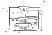
空調システム101は、冷媒を圧縮する圧縮機3と、圧縮された冷媒を放熱させて凝縮する凝縮器5と、凝縮器5からの冷媒を膨張させる膨張弁103と、膨張弁103からの冷媒と空調用空気とを熱交換する空調用蒸発器9と、空調用蒸発器9の表面温度を常に露点以上に保つコントローラ11とを有する空気調和装置105と、空調用空気を除湿する除湿手段15とを備えている。
The
また、コントローラ11は、膨張弁103の開度と、圧縮機3の冷媒吐出量とを制御することによって空調用蒸発器9を常に露点以上に保持している。
Further, the
除湿手段15は、冷媒を圧縮する圧縮機3と、圧縮された冷媒を放熱させて凝縮する凝縮器5と、凝縮器5からの冷媒を膨張させる膨張弁19と、膨張弁19からの冷媒と空調用空気とを熱交換する除湿用蒸発器21と、除湿用蒸発器21の表面温度を常に露点以下に保つコントローラ11とを備えている。
The dehumidifying means 15 includes a
次に、空調システム101の構成を説明する。
Next, the configuration of the
膨張弁103は、電動制御式、あるいは、機械制御式の膨張弁であり、コントローラ11によって開度調整される。また、コントローラ11は湿度センサー27によって空調用蒸発器9の出口側湿度をモニターしながら、通過空気(空調用蒸発器9を通過する熱交換空気)の相対湿度が80%〜85%になるように、圧縮機3の吐出量を制御し、膨張弁103の開度を調整する。コントローラ11による圧縮機3の吐出量制御と膨張弁103の開度調整は、湿度センサーで検知した空調用蒸発器9の出口側湿度、入口側湿度、水分量に基づいて行われ、あるいは、この制御に必要な数値がコントローラ11に予めマッピングされている。
The
相対湿度を80%〜85%に保たれた通過空気は、温度が露点以下になることがなくなって凝縮が防止され、空調用蒸発器9のフィンに凝縮水が付着することが防止される。
The passing air maintained at a relative humidity of 80% to 85% is prevented from condensing because the temperature does not fall below the dew point, and condensed water is prevented from adhering to the fins of the
また、コントローラ11は、圧縮機3の吐出量とブロワー25の風量を調整することによって、除湿用蒸発器21の通過空気を露点以下の温度に保ち、常に凝縮が生じるように制御している。
In addition, the
なお、図2に破線で示したように、出口側の湿度センサー27の代わりに、入口側の湿度センサー33を用いて空調用蒸発器9の入口側で湿度を検知するように構成してもよい。
In addition, as indicated by a broken line in FIG. 2, the humidity may be detected on the inlet side of the air-
次に、空調システム101の効果を説明する。
Next, the effect of the
空調用蒸発器9の結露が防止される上に、除湿手段15を併用することによって空気調和装置105(空調用蒸発器9)は常に乾燥した空気を扱うことができるから、においの発生を抑えることが出来る。
Condensation of the air-
また、吹き出し温度の制限から開放されるため、吹き出し温度を露点より高くすることが可能となり、吹き出し温度を上げる事で温水ヒーターなどで再加熱することなく室内を快適に制御することができる。 Further, since the restriction on the blowing temperature is released, the blowing temperature can be made higher than the dew point, and by raising the blowing temperature, the room can be comfortably controlled without reheating with a hot water heater or the like.
また、空気調和装置105は、凝縮温度の低い乾燥空気を扱うから、水分の凝縮を心配せずに、目標温度を充分低く設定することによって最高の空調機能を発揮させることが可能になる。
In addition, since the
特に、夏季の車両は熱負荷が大きく、狭い車室を強力に冷房する必要があり、それだけ乾燥し易いが、空調システム101では、上記のように空気調和装置105による空調機能と除湿手段15による除湿機能とを互いに分離して稼働させることにより、精密な温度及び湿度の制御が可能になり、車室内を常に快適な状態に保つことができる。
In particular, a vehicle in summer has a large heat load, and it is necessary to strongly cool a narrow passenger compartment and it is easy to dry. However, in the
また、空調用蒸発器9のフィンに凝縮水が付着しないから、凝縮水による通気抵抗が低減され、熱交換率が向上して高性能になると共に、フィンのピッチを充分に狭くすることができるから、空調システム101をそれだけコンパクトに構成することが可能になる。
Further, since condensed water does not adhere to the fins of the
また、空気調和装置105は、冷房負荷が低いとき臭気の問題がないために蒸発器温度を高く設定する事ができるので、COP(成績係数:エネルギー効率)がそれだけ向上する。
In addition, since the
また、除湿手段15だけを優先的に稼働させれば、車室温度を大きく低下させずに除湿することが可能であり、車室内を快適に保つことができる。 Further, if only the dehumidifying means 15 is operated preferentially, it is possible to perform dehumidification without greatly reducing the passenger compartment temperature, and the passenger compartment can be kept comfortable.
また、除湿が不要なときは、除湿手段15を停止すれば、エンジンの燃費を向上させることができる。 Further, when dehumidification is unnecessary, the fuel consumption of the engine can be improved by stopping the dehumidifying means 15.
また、除湿手段15(除湿用蒸発器21)の通過空気は常に露点以下に保たれており、フィンが常に凝縮水で濡れた状態にあって乾くことがないから、除湿用蒸発器21でも悪臭が発生することはない。 Further, the air passing through the dehumidifying means 15 (dehumidifying evaporator 21) is always kept below the dew point, and the fins are always wet with condensed water and do not dry. Will not occur.
従って、同一の蒸発器を空調と除湿に共用する特許文献2の従来技術と異なり、除湿手段15は、臭いの発生を避けるために運転条件(制御)を制約されることがなく、常に、最高の効率で稼働させることができるから、COPがさらに向上する。
Therefore, unlike the prior art of
<第3実施形態>
図3を参照しながら本発明の空調システム201を説明する。図3は空調システム201の構成を示すブロック図である。以下、空調システム1(第1実施形態)と同一の機能部及び機能部材には同一の符号を付しており、重複する説明文は省略するが、必要に応じて第1実施形態の説明文と図1とを参照するものとする。
<Third Embodiment>
The
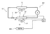
空調システム201は、冷媒を圧縮する圧縮機3と、圧縮された冷媒を放熱させて凝縮する凝縮器5と、凝縮器5からの冷媒を膨張させる膨張弁7と、膨張弁7からの冷媒と空調用空気とを熱交換する空調用蒸発器9と、空調用蒸発器9の表面温度を常に露点以上に保つコントローラ11とを有する空気調和装置13と、空調用空気を除湿する除湿手段203とを備えている。
The
また、空調用蒸発器9に熱交換空気(空調用空気)を送るブロワー17を有し、
コントローラ11が、ブロワー17の風量を制御することによって空調用蒸発器9の表面温度を常に露点以上に保持している。
Moreover, it has the
The
除湿手段203は、冷媒ガスと空調用空気とを熱交換する除湿用蒸発器と、この除湿用蒸発器を常に露点以下に保つコントローラ11とを備えている。
The dehumidifying means 203 includes a dehumidifying evaporator that exchanges heat between refrigerant gas and air-conditioning air, and a
次に、空調システム201の構成を説明する。
Next, the configuration of the
コントローラ11は湿度センサー27によって空調用蒸発器9の出口側湿度をモニターしながら、通過空気(空調用蒸発器9を通過する熱交換空気)の相対湿度が80%〜85%になるように、ブロワー17の風量を制御する。コントローラ11によるブロワー17の風量制御は、湿度センサーで検知した空調用蒸発器9の出口側湿度、入口側湿度、水分量に基づいて行われ、あるいは、この制御に必要な数値をコントローラ11に予めマッピングしているか、計算して求める。
While the
相対湿度を80%〜85%に保たれた通過空気は、温度が露点以下になることがなくなって凝縮が防止され、空調用蒸発器9のフィンに凝縮水が付着することが防止される。
The passing air maintained at a relative humidity of 80% to 85% is prevented from condensing because the temperature does not fall below the dew point, and condensed water is prevented from adhering to the fins of the
また、除湿手段203において、コントローラ11は、除湿用蒸発器の通過空気を露点以下の温度に保ち、常に結露している状態に制御している。
In the dehumidifying means 203, the
次に、空調システム201の効果を説明する。
Next, the effect of the
空調用蒸発器9の結露が防止される上に、除湿手段203を併用することによって空気調和装置13(空調用蒸発器9)は常に乾燥した空気を扱うことができるから、凝縮水による悪臭から解放され、車室は快適に保たれる。
Condensation of the
また、空気調和装置13は、凝縮温度の低い乾燥空気を扱うから、水分の凝縮を心配せずに、目標温度を充分低く設定することによって最高の空調機能を発揮させることが可能になる。
In addition, since the
特に、夏季の車両は熱負荷が大きく、狭い車室を強力に冷房する必要があり、それだけ乾燥し易いが、空調システム201では、上記のように空気調和装置13による空調機能と除湿手段203による除湿機能とを互いに分離して稼働させることにより、精密な温度及び湿度の制御が可能になり、車室内を常に快適な状態に保つことができる。
In particular, a vehicle in summer has a large heat load, and it is necessary to strongly cool a narrow passenger compartment and it is easy to dry. However, in the
また、空調用蒸発器9のフィンに凝縮水が付着しないから、凝縮水による通気抵抗が低減され、熱交換率が向上して高性能になると共に、フィンのピッチを充分に狭くすることができるから、空調システム201をそれだけコンパクトに構成することが可能になる。
Further, since condensed water does not adhere to the fins of the
また、空気調和装置13は、空調用蒸発器9の熱交換率向上に伴って、最大の効率で稼働させることが可能になるから、COP(成績係数:エネルギー効率)がそれだけ向上する。
Further, since the
また、除湿手段203だけを優先的に稼働させれば、車室温度を大きく低下させずに除湿することが可能であり、車室内を快適に保つことができる。 Further, if only the dehumidifying means 203 is operated preferentially, it is possible to dehumidify without greatly lowering the passenger compartment temperature, and the passenger compartment can be kept comfortable.
また、除湿が不要なときは、除湿手段203を停止すれば、エンジンの燃費を向上させることができる。 Further, when dehumidification is unnecessary, the fuel consumption of the engine can be improved by stopping the dehumidifying means 203.
また、除湿手段203の通過空気は常に露点以下に保たれており、フィンが常に凝縮水で濡れた状態にあって乾くことがないから、除湿手段203でも悪臭が発生することはない。 Further, since the air passing through the dehumidifying means 203 is always kept below the dew point and the fins are always wet with the condensed water and do not dry, the dehumidifying means 203 does not generate a bad odor.
従って、同一の蒸発器を空調と除湿に共用する特許文献2の従来技術と異なり、除湿手段203は、臭いの発生を避けるために運転条件(制御)を制約されることがなく、常に、最高の効率で稼働させることができるから、COPがさらに向上する。
Therefore, unlike the prior art of
<第4実施形態>
図4を参照しながら本発明の空調システム301を説明する。図4は空調システム301の構成を示す模式図である。以下、空調システム1(第1実施形態)と同一の機能部及び機能部材には同一の符号を付しており、重複する説明文は省略するが、必要に応じて第1実施形態の説明文と図1とを参照するものとする。
<Fourth embodiment>
The
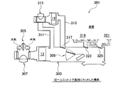
空調システム301は、空気調和装置13と、除湿手段15とを備えている。また、空気調和装置13と除湿手段15は、同一の空調ダクト303(筐体)にユニット化されている。
The
空調システム301は、車両用の空調システムであり、空調ダクト303には、内外気切替ドア305と、吸入ブロワー307と、エアミックスドア309と、除湿手段15用の吸入ダクト311及び吐出ダクト313と、吸入ダクト311に取り付けられたブーストファン315と、吐出ダクト313を開閉するドア317と、車室側のダクト319,321を開閉するドア323,325などが取り付けられている。
The
空気調和装置13は、内外気切替ドア305によって内気と外気の吸入割合を調整し、吸入ブロワー307はその割合で空気を吸入し、吸入された空気を空調し、除湿手段15は、この空調された空気をブーストファン315により吸入ダクト311から吸入し、除湿した空気を吐出ダクト313とドア317とを介して空調ダクト303に戻し、エアミックスドア309は空気調和装置13からの空調空気と除湿手段15からの除湿空気の混合割合を調整し、ドア323,325からダクト319,321を介して車室側に吹き出す。
The
このように、空調システム301は、同一のユニット上で、空気調和装置13と除湿手段15とを、空気の流れの方向に、この順序で直列配置し、空調用空気が、空気調和装置13で空調された後、除湿手段15で除湿されるように構成した。
Thus, the
従って、除湿手段と空気調和装置を反対の順序で配置することに起因する除湿側蒸発器からの凝縮水が空調側蒸発器に付着し悪臭を発生することが回避される。 Therefore, it is avoided that the condensed water from the dehumidifying side evaporator due to the arrangement of the dehumidifying means and the air conditioner in the reverse order adheres to the air conditioning side evaporator and generates malodor.
また、空調システム301は、空気調和装置13と除湿手段15を空調ダクト303でユニット化したことにより、それだけコンパクトに構成され、車載性が向上している。
In addition, the
<第5実施形態>
図5を参照しながら本発明の空調システム401を説明する。図5は空調システム401の構成を示す模式図である。以下、空調システム1(第1実施形態)と同一の機能部及び機能部材には同一の符号を付しており、重複する説明文は省略するが、必要に応じて第1実施形態の説明文と図1とを参照するものとする。
<Fifth Embodiment>
The
空調システム401は、
空気調和装置13と、除湿手段15とを備えている。
The
An
また、空気調和装置13と除湿手段15は、個別の空調ダクト403,405(筐体)に収容されている。
The
空調システム401は、車両407に用いられた空調システムであり、空気調和装置13の空調ダクト403には、内外気切替ドア409と、吸入ブロワー411と、エアミックスドア413と、車室から内気を取り入れるドア415と、車室側のダクト417,419を開閉するドア421,423などが取り付けられている。また、除湿手段15の空調ダクト405には、吸入ブロワー425と、吹き出し口427などが取り付けられている。
The air-
空気調和装置13は、内外気切替ドア409によって内気と外気の吸入割合を調整し、吸入ダクト411はその割合で空気を吸入し、吸入された空気を空調し、エアミックスドア413によって空調空気とドア415から取り入れた内気との混合割合を調整し、ドア421,423からダクト417,419を介して車室側に吹き出す。
The
また、除湿手段15は、吸入ブロワー425が吸入した内気を除湿し、吹き出し口427から車室側に吹き出す。
Further, the dehumidifying means 15 dehumidifies the inside air sucked by the
このように、空調システム401は、空気調和装置13と除湿手段15とを空気の流れの方向に並列配置し、空気調和装置13で空調された空調用空気と、除湿手段15で除湿された空調用空気とを混合して車室に供給するように構成されている。
Thus, the
また、空気調和装置13と除湿手段15とを別のユニットで構成したことにより、既存の除湿専用装置を除湿手段15として利用することが可能になるから、最適な除湿手段15をそれだけ広い範囲から選択することができる。
Moreover, since the
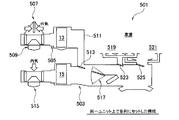
<第6実施形態>
図6を参照しながら本発明の空調システム501を説明する。図6は空調システム501の構成を示す模式図である。以下、空調システム1(第1実施形態)と同一の機能部及び機能部材には同一の符号を付しており、重複する説明文は省略するが、必要に応じて第1実施形態の説明文と図1とを参照するものとする。
<Sixth Embodiment>
The
空調システム501は、
空気調和装置13と、除湿手段15とを備えている。
The
An
また、空気調和装置13と除湿手段15は、同一の空調ダクト503(筐体)にユニット化されている。
The
空調システム501は、車両用の空調システムであり、空調ダクト503には、空気調和装置13用のダクト505が連結されている。ダクト505には、内外気切替ドア507と、吸入ブロワー509と、空調ダクト503に連結する連結ダクト511と、連結ダクト511を開閉するドア513が取り付けられており、空調ダクト503には、吸入ブロワー515と、エアミックスドア517と、車室側のダクト519,521を開閉するドア523,525などが取り付けられている。
The
空気調和装置13は、内外気切替ドア507によって内気と外気の吸入割合を調整し、吸入ブロワー509はその割合で空気を吸入し、吸入された空気を空調し、連結ダクト511からドア513を介して空調ダクト503に吐出し、除湿手段15は、吸入ブロワー515によって内気を吸入して除湿し、除湿された空気と空気調和装置13で空調された空気との混合割合をエアミックスドア517によって調整し、ドア523,525からダクト519,521を介して車室側に吹き出す。
The
このように、空調システム501は、空気調和装置13で空調された空調用空気と、除湿手段15で除湿された空調用空気とを混合して車室に供給するように構成されており、空気調和装置13と除湿手段15を空調ダクト503でユニット化したことにより、それだけコンパクトに構成され、車載性が向上している。
Thus, the
次に、図7の空気線図によって実施例1と実施例2と実施例3の説明をする。 Next, Example 1, Example 2, and Example 3 will be described with reference to the air diagram of FIG.
各実施例は、例えば、実施形態1の空調システム1を用い、異なった状態量(空気温度、絶対湿度、相対湿度、エンタルピー)で、空調及び除湿した場合に、空気調和装置13の空調用蒸発器9と除湿手段15の除湿用蒸発器21にそれぞれ掛かる負担の割合と、空調及び除湿前後の各状態量の変化を測定し空気線図上に示したものである。
Each example uses, for example, the air conditioning system 1 of the first embodiment, and when the air conditioning and dehumidification are performed with different state quantities (air temperature, absolute humidity, relative humidity, enthalpy), the
各実施例において、矢印Aは、空気調和装置13によって外気を結露しないように空調したときの変化を示し、矢印Bは、空気調和装置13で空調されて内気となった空気を除湿手段15によって除湿したときの変化を示し、矢印Cは、空気調和装置13での空調と除湿手段15での除湿を同時に行ったときの変化を示している。なお、実施例3は除湿する必要のない場合であり、従って、矢印Bと矢印Cの変化は示されていない。
In each embodiment, an arrow A indicates a change when air conditioning is performed so that the outside air is not condensed by the
また、実施例1のE1AとE1Bは矢印Aの空調と矢印Bの除湿に伴う各エンタルピーの変化量をそれぞれ示し、実施例2のE2AとE2Bは矢印Aの空調と矢印Bの除湿に伴う各エンタルピーの変化量をそれぞれ示し、実施例3のE3Aは矢印Aの空調に伴うエンタルピーの変化量を示している。 Moreover, E1A and E1B of Example 1 show the amount of change of each enthalpy accompanying the air conditioning of arrow A and dehumidification of arrow B, respectively, and E2A and E2B of Example 2 are each of the air conditioning of arrow A and each dehumidifying of arrow B The amount of change in enthalpy is shown, and E3A in Example 3 shows the amount of change in enthalpy accompanying the air conditioning of arrow A.
各実施例のように、空気調和装置13は結露しないように動作することによって悪臭が防止され、除湿手段15は凝縮水が乾かないように動作することによって悪臭が防止される。
As in each embodiment, the
また、実施例3のように、除湿が不要なときは除湿手段15を稼働させないからエンタルピーの変化量(E3A)が少なく、エンジンの燃費がそれだけ向上する。 Further, as in the third embodiment, when the dehumidification is unnecessary, the dehumidifying means 15 is not operated, so that the enthalpy change amount (E3A) is small, and the fuel consumption of the engine is improved accordingly.
[本発明の範囲に含まれる他の態様]
なお、本発明は上述した実施形態のみに限定解釈されるものではなく、本発明の技術的な範囲内で様々な変更が可能である。
[Other Embodiments Included within the Scope of the Present Invention]
It should be noted that the present invention is not limited to the above-described embodiment, and various modifications can be made within the technical scope of the present invention.
例えば、本発明の空調システムは、車両以外に用いてもよい。 For example, you may use the air-conditioning system of this invention other than a vehicle.
1 空調システム
3 圧縮機
5 凝縮器
7 膨張弁
9 空調用蒸発器
11 コントローラ
13 空気調和装置
15 除湿手段
17 ブロワー
19 膨張弁
21 除湿用蒸発器
101 空調システム
103 膨張弁
105 空気調和装置
201 空調システム
203 除湿手段
301 空調システム
303 空調ダクト(筐体)
401 空調システム
403,405 空調ダクト(筐体)
501 空調システム
503 空調ダクト(筐体)
DESCRIPTION OF SYMBOLS 1
401
501
Claims (13)
圧縮された冷媒を放熱させて凝縮する凝縮器(5)と、
前記凝縮器(5)からの冷媒を膨張させる膨張弁(7,103)と、
前記膨張弁(7,103)からの冷媒と空調用空気とを熱交換する空調用蒸発器(9)と、
前記空調用蒸発器(9)の表面温度を常に露点以上に保つコントローラ(11)とを有する空気調和装置(13,105)と、
前記空調用空気を除湿する除湿手段(15,203)とを備えていることを特徴とする空調システム。 A compressor (3) for compressing the refrigerant;
A condenser (5) that dissipates heat and condenses the compressed refrigerant;
An expansion valve (7, 103) for expanding the refrigerant from the condenser (5);
An air conditioning evaporator (9) for exchanging heat between the refrigerant from the expansion valve (7, 103) and the air for air conditioning;
An air conditioner (13, 105) having a controller (11) that keeps the surface temperature of the air conditioning evaporator (9) always above the dew point;
An air conditioning system comprising dehumidifying means (15, 203) for dehumidifying the air for air conditioning.
前記空調用蒸発器(9)に熱交換空気を送るブロワー(17)を有し、
前記コントローラ(11)が、前記ブロワー(17)の風量と前記圧縮機(3)の冷媒吐出量の少なくとも一方を制御することによって前記空調用蒸発器(9)の表面温度を常に露点以上に保つことを特徴とする空調システム。 An air conditioning system according to claim 1,
A blower (17) for sending heat exchange air to the air conditioning evaporator (9);
The controller (11) controls at least one of the air volume of the blower (17) and the refrigerant discharge amount of the compressor (3), so that the surface temperature of the air conditioning evaporator (9) is always kept above the dew point. An air conditioning system characterized by that.
前記コントローラ(11)が、前記膨張弁(103)の開度と前記圧縮機(3)の冷媒吐出量の少なくとも一方を制御することによって前記空調用蒸発器(9)の表面温度を常に露点以上に保つことを特徴とする空調システム。 An air conditioning system according to claim 1,
The controller (11) controls at least one of the opening degree of the expansion valve (103) and the refrigerant discharge amount of the compressor (3) so that the surface temperature of the air conditioning evaporator (9) is always above the dew point. An air conditioning system characterized by keeping
前記除湿手段(15,203)が、
冷媒を圧縮する圧縮機(3)と、
圧縮された冷媒を放熱させて凝縮する凝縮器(5)と、
前記凝縮器(5)からの冷媒を膨張させる膨張弁(19)と、
前記膨張弁(19)からの冷媒と前記空調用空気とを熱交換する除湿用蒸発器(21)と、
前記除湿用蒸発器(21)を常に露点以下に保つコントローラ(11)とを備えていることを特徴とする空調システム。 An air conditioning system according to any one of claims 1 to 3,
The dehumidifying means (15, 203)
A compressor (3) for compressing the refrigerant;
A condenser (5) that dissipates heat and condenses the compressed refrigerant;
An expansion valve (19) for expanding the refrigerant from the condenser (5);
A dehumidification evaporator (21) for exchanging heat between the refrigerant from the expansion valve (19) and the air for air conditioning;
An air conditioning system comprising: a controller (11) that keeps the dehumidifying evaporator (21) always below a dew point.
前記除湿手段が、吸着剤によって前記空調用空気から水分を吸着し、除湿するように構成されていることを特徴とする空調システム。 An air conditioning system according to any one of claims 1 to 3,
An air conditioning system, wherein the dehumidifying means is configured to adsorb moisture from the air-conditioning air by an adsorbent and dehumidify the moisture.
前記除湿手段(15,203)と前記空気調和装置(13,105)とが、同一の筐体(303)にユニット化されており、
前記空気調和装置(13,105)と前記除湿手段(15,203)が、空調用空気の流れの方向にこの順序で直列に配置され、
前記空調用空気が、前記空気調和装置(13,105)で空調された後、前記除湿手段(15,203)で除湿されて室内に供給されることを特徴とする空調システム。 An air conditioning system according to any one of claims 1 to 5,
The dehumidifying means (15, 203) and the air conditioner (13, 105) are unitized in the same casing (303),
The air conditioner (13, 105) and the dehumidifying means (15, 203) are arranged in series in this order in the direction of the air-conditioning air flow,
The air conditioning system is characterized in that the air for air conditioning is air-conditioned by the air conditioner (13, 105), dehumidified by the dehumidifying means (15, 203), and supplied indoors.
前記除湿手段(15,203)と前記空気調和装置(13,105)とが、同一の筐体(503)にユニット化されており、
前記空気調和装置(13,105)と前記除湿手段(15,203)が、空調用空気の流れの方向に並列配置され、
前記空気調和装置(13,105)によって空調された前記空調用空気と、前記除湿手段(15,203)によって除湿された前記空調用空気とが混合された後室内に供給されることを特徴とする空調システム。 An air conditioning system according to any one of claims 1 to 5,
The dehumidifying means (15, 203) and the air conditioner (13, 105) are unitized in the same casing (503),
The air conditioner (13, 105) and the dehumidifying means (15, 203) are arranged in parallel in the direction of air-conditioning air flow,
The air conditioning air conditioned by the air conditioner (13, 105) and the air conditioned dehumidified by the dehumidifying means (15, 203) are mixed and then supplied to the room. Air conditioning system.
前記除湿手段(15,203)と前記空気調和装置(13,105)とが、互いに異なった筐体(403,405)に収容されており、
前記空気調和装置(13,105)と前記除湿手段(15,203)が、空調用空気の流れの方向に並列配置され、
前記空気調和装置(13,105)によって空調された前記空調用空気と、前記除湿手段(15,203)によって除湿された前記空調用空気とが混合された後室内に供給されることを特徴とする空調システム。 An air conditioning system according to any one of claims 1 to 5,
The dehumidifying means (15, 203) and the air conditioner (13, 105) are housed in different housings (403, 405),
The air conditioner (13, 105) and the dehumidifying means (15, 203) are arranged in parallel in the direction of air-conditioning air flow,
The air conditioning air conditioned by the air conditioner (13, 105) and the air conditioned dehumidified by the dehumidifying means (15, 203) are mixed and then supplied to the room. Air conditioning system.
圧縮された冷媒を放熱させて凝縮する凝縮器(5)と、
前記凝縮器(5)からの冷媒を膨張させる膨張弁(7,103)と、
前記膨張弁(7,103)からの冷媒と空調用空気とを熱交換する空調用蒸発器(9)と、
前記空調用空気を除湿する除湿手段(15,203)とを備えた空調システムの制御方法であって、
前記空調用蒸発器(9)の表面温度が常に露点以上に保たれるように制御することを特徴とする空調システムの制御方法。 A compressor (3) for compressing the refrigerant;
A condenser (5) that dissipates heat and condenses the compressed refrigerant;
An expansion valve (7, 103) for expanding the refrigerant from the condenser (5);
An air conditioning evaporator (9) for exchanging heat between the refrigerant from the expansion valve (7, 103) and the air for air conditioning;
A control method for an air conditioning system comprising dehumidifying means (15, 203) for dehumidifying the air for air conditioning,
A control method for an air conditioning system, characterized in that control is performed so that the surface temperature of the air conditioning evaporator (9) is always maintained at or above a dew point.
前記空調用蒸発器(9)に熱交換空気を送るブロワー(17)の風量と前記圧縮機(3)の冷媒吐出量の少なくとも一方を制御することによって前記空調用蒸発器(9)の表面温度を常に露点以上に保つことを特徴とする空調システムの制御方法。 A method for controlling an air conditioning system according to claim 9,
The surface temperature of the air conditioning evaporator (9) is controlled by controlling at least one of the air volume of the blower (17) that sends heat exchange air to the air conditioning evaporator (9) and the refrigerant discharge amount of the compressor (3). A control method for an air conditioning system, characterized by always maintaining the dew point above the dew point.
前記膨張弁(103)の開度と前記圧縮機(3)の冷媒吐出量の少なくとも一方を制御することによって前記空調用蒸発器(9)の表面温度を常に露点以上に保つことを特徴とする空調システムの制御方法。 A method for controlling an air conditioning system according to claim 9,
By controlling at least one of the opening degree of the expansion valve (103) and the refrigerant discharge amount of the compressor (3), the surface temperature of the air conditioning evaporator (9) is always kept above the dew point. Control method for air conditioning system.
前記除湿手段(15)が、
冷媒を圧縮する圧縮機(3)と、
圧縮された冷媒を放熱させて凝縮する凝縮器(5)と、
前記凝縮器(5)からの冷媒を膨張させる膨張弁(19)と、
前記膨張弁(19)からの冷媒と前記空調用空気とを熱交換する除湿用蒸発器(21)とを備えており、
前記除湿用蒸発器(21)が常に露点以下に保たれるように制御することを特徴とする空調システムの制御方法。 A control method for an air conditioning system according to any one of claims 9 to 11,
The dehumidifying means (15)
A compressor (3) for compressing the refrigerant;
A condenser (5) that dissipates heat and condenses the compressed refrigerant;
An expansion valve (19) for expanding the refrigerant from the condenser (5);
A dehumidification evaporator (21) for exchanging heat between the refrigerant from the expansion valve (19) and the air-conditioning air,
A control method for an air conditioning system, wherein the dehumidifying evaporator (21) is controlled so as to be always kept below a dew point.
前記除湿手段が、吸着剤によって前記空調用空気から水分を吸着し、除湿するように構成されていることを特徴とする空調システムの制御方法。 A control method for an air conditioning system according to any one of claims 9 to 11,
The method of controlling an air conditioning system, wherein the dehumidifying means is configured to adsorb moisture from the air-conditioning air by an adsorbent and dehumidify the moisture.
Priority Applications (1)
| Application Number | Priority Date | Filing Date | Title |
|---|---|---|---|
| JP2008201081A JP5113664B2 (en) | 2008-08-04 | 2008-08-04 | Air conditioning system |
Applications Claiming Priority (1)
| Application Number | Priority Date | Filing Date | Title |
|---|---|---|---|
| JP2008201081A JP5113664B2 (en) | 2008-08-04 | 2008-08-04 | Air conditioning system |
Publications (2)
| Publication Number | Publication Date |
|---|---|
| JP2010038432A true JP2010038432A (en) | 2010-02-18 |
| JP5113664B2 JP5113664B2 (en) | 2013-01-09 |
Family
ID=42011185
Family Applications (1)
| Application Number | Title | Priority Date | Filing Date |
|---|---|---|---|
| JP2008201081A Expired - Fee Related JP5113664B2 (en) | 2008-08-04 | 2008-08-04 | Air conditioning system |
Country Status (1)
| Country | Link |
|---|---|
| JP (1) | JP5113664B2 (en) |
Cited By (5)
| Publication number | Priority date | Publication date | Assignee | Title |
|---|---|---|---|---|
| KR20150067526A (en) * | 2013-12-10 | 2015-06-18 | 엘지전자 주식회사 | Dehumidifier |
| JP2016205635A (en) * | 2015-04-15 | 2016-12-08 | 一般財団法人電力中央研究所 | Heat pump system |
| CN106839532A (en) * | 2017-03-24 | 2017-06-13 | 合肥天鹅制冷科技有限公司 | Air-conditioning system evaporator antifrost icing device |
| CN108645065A (en) * | 2018-06-12 | 2018-10-12 | 泰豪科技股份有限公司 | Temperature adjusting and dehumidifying system and air handling system |
| CN110736142A (en) * | 2019-10-12 | 2020-01-31 | 海信(山东)空调有限公司 | air conditioner and rapid dehumidification control method without cooling |
Citations (13)
| Publication number | Priority date | Publication date | Assignee | Title |
|---|---|---|---|---|
| JPS5683418U (en) * | 1979-11-29 | 1981-07-06 | ||
| JPS5724428U (en) * | 1980-07-17 | 1982-02-08 | ||
| JPS6317112A (en) * | 1986-07-09 | 1988-01-25 | Nippon Denso Co Ltd | Air purifier for passenger's compartment of vehicle |
| JPS63107227U (en) * | 1986-12-27 | 1988-07-11 | ||
| JPH04214136A (en) * | 1990-12-10 | 1992-08-05 | Hitachi Metals Ltd | Air-conditioning facility |
| JPH06101894A (en) * | 1992-09-08 | 1994-04-12 | Hitachi Ltd | Air-conditioning system |
| JPH0996433A (en) * | 1995-09-29 | 1997-04-08 | Toshiba Corp | Air conditioner |
| JPH11198644A (en) * | 1998-01-19 | 1999-07-27 | Denso Corp | Vehicular air conditioner |
| JP2000146220A (en) * | 1998-11-02 | 2000-05-26 | Nissan Motor Co Ltd | Air conditioning means and air conditioner |
| JP2003247741A (en) * | 2002-02-24 | 2003-09-05 | Kiyoshi Yanagimachi | Air conditioning facility |
| JP2005049059A (en) * | 2003-07-31 | 2005-02-24 | Daikin Ind Ltd | Air-conditioning system |
| JP2005147623A (en) * | 2003-11-19 | 2005-06-09 | Mitsubishi Electric Corp | Air conditioner, and operating method for air conditioner |
| JP2006275399A (en) * | 2005-03-29 | 2006-10-12 | Mitsubishi Electric Corp | Air conditioner |
-
2008
- 2008-08-04 JP JP2008201081A patent/JP5113664B2/en not_active Expired - Fee Related
Patent Citations (13)
| Publication number | Priority date | Publication date | Assignee | Title |
|---|---|---|---|---|
| JPS5683418U (en) * | 1979-11-29 | 1981-07-06 | ||
| JPS5724428U (en) * | 1980-07-17 | 1982-02-08 | ||
| JPS6317112A (en) * | 1986-07-09 | 1988-01-25 | Nippon Denso Co Ltd | Air purifier for passenger's compartment of vehicle |
| JPS63107227U (en) * | 1986-12-27 | 1988-07-11 | ||
| JPH04214136A (en) * | 1990-12-10 | 1992-08-05 | Hitachi Metals Ltd | Air-conditioning facility |
| JPH06101894A (en) * | 1992-09-08 | 1994-04-12 | Hitachi Ltd | Air-conditioning system |
| JPH0996433A (en) * | 1995-09-29 | 1997-04-08 | Toshiba Corp | Air conditioner |
| JPH11198644A (en) * | 1998-01-19 | 1999-07-27 | Denso Corp | Vehicular air conditioner |
| JP2000146220A (en) * | 1998-11-02 | 2000-05-26 | Nissan Motor Co Ltd | Air conditioning means and air conditioner |
| JP2003247741A (en) * | 2002-02-24 | 2003-09-05 | Kiyoshi Yanagimachi | Air conditioning facility |
| JP2005049059A (en) * | 2003-07-31 | 2005-02-24 | Daikin Ind Ltd | Air-conditioning system |
| JP2005147623A (en) * | 2003-11-19 | 2005-06-09 | Mitsubishi Electric Corp | Air conditioner, and operating method for air conditioner |
| JP2006275399A (en) * | 2005-03-29 | 2006-10-12 | Mitsubishi Electric Corp | Air conditioner |
Cited By (6)
| Publication number | Priority date | Publication date | Assignee | Title |
|---|---|---|---|---|
| KR20150067526A (en) * | 2013-12-10 | 2015-06-18 | 엘지전자 주식회사 | Dehumidifier |
| KR102194676B1 (en) * | 2013-12-10 | 2020-12-24 | 엘지전자 주식회사 | Dehumidifier |
| JP2016205635A (en) * | 2015-04-15 | 2016-12-08 | 一般財団法人電力中央研究所 | Heat pump system |
| CN106839532A (en) * | 2017-03-24 | 2017-06-13 | 合肥天鹅制冷科技有限公司 | Air-conditioning system evaporator antifrost icing device |
| CN108645065A (en) * | 2018-06-12 | 2018-10-12 | 泰豪科技股份有限公司 | Temperature adjusting and dehumidifying system and air handling system |
| CN110736142A (en) * | 2019-10-12 | 2020-01-31 | 海信(山东)空调有限公司 | air conditioner and rapid dehumidification control method without cooling |
Also Published As
| Publication number | Publication date |
|---|---|
| JP5113664B2 (en) | 2013-01-09 |
Similar Documents
| Publication | Publication Date | Title |
|---|---|---|
| JP4232463B2 (en) | Air conditioner | |
| JP4169747B2 (en) | Air conditioner | |
| JP2968241B2 (en) | Dehumidifying air conditioning system and operating method thereof | |
| US20100300123A1 (en) | Hybrid desiccant dehumidifying apparatus and control method thereof | |
| JP4835688B2 (en) | Air conditioner, air conditioning system | |
| JP2009280020A (en) | Air conditioner for vehicle and method for controlling the same | |
| JP2001241693A (en) | Air conditioner | |
| JP4502054B2 (en) | Air conditioner | |
| JP2006329471A (en) | Air conditioning system | |
| JP4639485B2 (en) | Air conditioner | |
| JP2010071587A (en) | Air conditioning system | |
| JP5113664B2 (en) | Air conditioning system | |
| JP4538846B2 (en) | Air conditioner | |
| JP5828140B2 (en) | Air conditioner for vehicles | |
| JP5089254B2 (en) | Humidity conditioning air conditioning system for automobiles | |
| JP5542777B2 (en) | Air conditioner | |
| JP3821031B2 (en) | Desiccant air conditioning system | |
| JP3731113B2 (en) | Air conditioner | |
| WO2018190081A1 (en) | Electric-powered vehicle | |
| JP3249466B2 (en) | Humidification, ventilation and dehumidification units and air conditioners | |
| JP2006116981A (en) | Vehicular air-conditioner | |
| JP2020006865A (en) | Humidified air supply device | |
| JP4339149B2 (en) | Dehumidifying air conditioner | |
| JP4082191B2 (en) | Air conditioner | |
| WO2021005657A1 (en) | Air-conditioning apparatus |
Legal Events
| Date | Code | Title | Description |
|---|---|---|---|
| A621 | Written request for application examination |
Free format text: JAPANESE INTERMEDIATE CODE: A621 Effective date: 20100928 |
|
| A977 | Report on retrieval |
Free format text: JAPANESE INTERMEDIATE CODE: A971007 Effective date: 20120309 |
|
| A131 | Notification of reasons for refusal |
Free format text: JAPANESE INTERMEDIATE CODE: A131 Effective date: 20120321 |
|
| A521 | Written amendment |
Free format text: JAPANESE INTERMEDIATE CODE: A523 Effective date: 20120518 |
|
| TRDD | Decision of grant or rejection written | ||
| A01 | Written decision to grant a patent or to grant a registration (utility model) |
Free format text: JAPANESE INTERMEDIATE CODE: A01 Effective date: 20121009 |
|
| A01 | Written decision to grant a patent or to grant a registration (utility model) |
Free format text: JAPANESE INTERMEDIATE CODE: A01 |
|
| A61 | First payment of annual fees (during grant procedure) |
Free format text: JAPANESE INTERMEDIATE CODE: A61 Effective date: 20121012 |
|
| FPAY | Renewal fee payment (event date is renewal date of database) |
Free format text: PAYMENT UNTIL: 20151019 Year of fee payment: 3 |
|
| R150 | Certificate of patent or registration of utility model |
Free format text: JAPANESE INTERMEDIATE CODE: R150 |
|
| R250 | Receipt of annual fees |
Free format text: JAPANESE INTERMEDIATE CODE: R250 |
|
| LAPS | Cancellation because of no payment of annual fees |