JP2010037873A - Interior wall structure - Google Patents
Interior wall structure Download PDFInfo
- Publication number
- JP2010037873A JP2010037873A JP2008204320A JP2008204320A JP2010037873A JP 2010037873 A JP2010037873 A JP 2010037873A JP 2008204320 A JP2008204320 A JP 2008204320A JP 2008204320 A JP2008204320 A JP 2008204320A JP 2010037873 A JP2010037873 A JP 2010037873A
- Authority
- JP
- Japan
- Prior art keywords
- wall
- frame
- base frame
- heat insulating
- wall base
- Prior art date
- Legal status (The legal status is an assumption and is not a legal conclusion. Google has not performed a legal analysis and makes no representation as to the accuracy of the status listed.)
- Granted
Links
Images

Abstract
Description
本発明は、住宅等の建築物における内壁構造に関し、特に、鉄骨軸組躯体を有する建築物の外周壁に面して躯体の屋内側に断熱内壁パネルを建て込むことにより構成される高断熱型の内壁構造に関するものである。 TECHNICAL FIELD The present invention relates to an inner wall structure in a building such as a house, and in particular, a highly heat insulating type configured by building a heat insulating inner wall panel on the indoor side of a frame facing the outer peripheral wall of a building having a steel frame frame. It is related with the inner wall structure of.
住宅その他の一般的な建築物に採用される高断熱型の内壁構造として、鉄骨軸組躯体の屋内側に、枠体と断熱材とを一体化した断熱内壁パネルを建て込んで、その屋内側に石こうボードや壁紙等の内壁仕上げ材を施工する構造が知られている。本出願人も、その種の断熱内壁パネルや、該パネルを利用した内壁構造の施工技術を、特許文献1〜6等において提案し実用化している。
As a highly heat-insulated inner wall structure used in houses and other general buildings, a heat-insulated inner wall panel that integrates a frame and heat insulating material is built on the indoor side of a steel frame assembly, and the indoor side There are known structures for constructing interior wall finishing materials such as gypsum board and wallpaper. The present applicant has also proposed and put to practical use such a heat-insulated inner wall panel and a construction technique of an inner wall structure using the panel in
それらのうち、特許文献1、2に開示された技術は、木材からなる桟材を矩形に枠組みして木製の内壁下地枠を構成し、その屋外側に、例えばアルミニウム蒸着した樹脂フィルム等からなる防湿シートを貼設し、さらに、その屋外側に、グラスウールやロックウール等からなる繊維状の断熱材を樹脂フィルム等からなる袋体に封入したものを重ねて断熱内壁パネルを構成するものである。そして、その断熱内壁パネルを、鉄骨軸組構造からなる躯体の屋内側に建て込み、上記断熱材を軸組躯体と断熱内壁パネルとの間に挟み込むようにして、高い断熱性能を確保している。
Among them, the techniques disclosed in
また、特許文献3、4に開示された技術は、上記特許文献1、2に開示された断熱内壁パネルを構成する木製の桟材を、薄板軽量形鋼材等からなる金属製の桟材に置き換えたものであり、これによって施工性や施工品質の改善、部材規格の標準化等を図っている。
In addition, the techniques disclosed in
また、特許文献5、6に開示された技術は、上記特許文献1〜4に開示された断熱内壁パネルを、鉄骨軸組躯体から若干、離隔させた状態で軸組の柱材に固定するための取付部材に関するものである。
上記従来の内壁構造では、断熱内壁パネルを構成する内壁下地枠が、金属製の取付部材を介して、躯体を構成する軸組の柱材に固定される。したがって、内壁下地枠の幅方向の割り付けが躯体の柱割(柱材の配置間隔)に拘束されることとなって、これが設計・施工上の制約となるおそれがある。 In the above-described conventional inner wall structure, the inner wall base frame constituting the heat insulating inner wall panel is fixed to the columnar column member constituting the housing via the metal mounting member. Therefore, the allocation in the width direction of the inner wall base frame is constrained by the column division of the frame (arrangement interval of the column members), which may be a limitation in design and construction.
そして、断熱内壁パネルが躯体から若干、離隔して設けられるにしても、躯体の柱材と内壁下地枠とを連結する取付部材を介して熱橋が形成され、これが断熱設計上の弱点となる。内壁下地枠の桟材に、木材よりも熱伝導率の高い薄板軽量形鋼材を用いる場合はなおさらである。 And even if the heat insulation inner wall panel is provided slightly apart from the housing, a thermal bridge is formed via an attachment member that connects the pillar material of the housing and the inner wall base frame, which becomes a weak point in heat insulation design. . This is especially true when a thin lightweight steel material having a higher thermal conductivity than wood is used for the crosspiece of the inner wall base frame.
断熱性能を高めるために、例えば、軸組と内壁下地枠との間隔を拡げて、その間に挟み込む断熱材の厚みを増すことも考えられるが、軸組と内壁下地枠との間隔をむやみに拡げると、壁全体の納まり寸法が厚くなり、その分、屋内側のスペースが圧迫されてしまう。 In order to enhance the heat insulation performance, for example, it may be possible to increase the thickness of the heat insulating material sandwiched between the shaft assembly and the inner wall base frame, but the space between the shaft assembly and the inner wall base frame is increased gradually. As a result, the overall housing size of the wall becomes thick, and the space on the indoor side is compressed accordingly.
近年では、省エネルギーに対する要求が厳しくなり、一般住宅等においても高い水準の断熱性能が求められるようになっている。そこで、本発明は、従来と同等以上の施工性や納まりにおけるスペース効率を保持しつつ、躯体と断熱内壁パネルとの間に熱橋が生じるのを回避して、より高い断熱性能を発揮しうる内壁構造を提供するものである。 In recent years, the demand for energy saving has become stricter, and a high level of heat insulation performance has been required even in ordinary houses. Therefore, the present invention can exhibit higher thermal insulation performance by avoiding the formation of a thermal bridge between the housing and the thermal insulation inner wall panel, while maintaining space efficiency in the construction and accommodation equivalent to or better than conventional ones. An inner wall structure is provided.
上記した目的を達成するため、本発明は、鉄骨軸組躯体の屋内側に断熱内壁パネルを建て込んで内壁下地となす内壁構造において、上記断熱内壁パネル(1)は、軽量形鋼材からなる縦横の桟材を矩形に枠組みして形成した内壁下地枠(2)の屋外側に防湿シート(3)を貼設し、さらにその屋外側にフィルム包装した変形可能な断熱材(4)を貼設したものであり、上記内壁下地枠(2)が上記躯体から屋内側に離隔して建て込まれるとともに、上記内壁下地枠(2)を構成する縦桟材(21)が上記躯体の柱位置に対し壁長方向にずれて配置され、上記躯体と内壁下地枠(2)との間に上記断熱材(4)が、躯体の柱位置で途切れず壁長方向に連続して介装されることを特徴とする。 In order to achieve the above-described object, the present invention provides an inner wall structure in which a heat insulating inner wall panel is built on the indoor side of a steel frame assemblage to serve as an inner wall base, and the heat insulating inner wall panel (1) is a vertical and horizontal made of a lightweight steel material. A moisture-proof sheet (3) is attached to the outdoor side of the inner wall base frame (2) formed by rectangular frame material, and a deformable heat insulating material (4) film-wrapped to the outdoor side. The inner wall base frame (2) is built on the indoor side away from the housing, and the vertical beam (21) constituting the inner wall base frame (2) is located at the column position of the housing. In contrast, the heat insulating material (4) is arranged so as to be shifted in the wall length direction, and the heat insulating material (4) is continuously interposed in the wall length direction between the frame and the inner wall base frame (2) without being interrupted at the column position of the frame. It is characterized by.
すなわち、この発明は、内壁下地枠(2)を鉄骨軸組躯体から離隔させ、かつ、内壁下地枠(2)の縦桟材(21)を躯体の柱位置からずらすことによって、内壁下地枠(2)の施工性を高めるとともに、躯体と内壁下地枠(2)との間に熱橋が形成されるのを回避しようとしたものである。この構成によれば、躯体の柱材(6)と内壁下地枠(2)との間に従来のような取付部材が介在しなくなるので、断熱材(4)を、躯体の柱位置で途切れさせることなく、躯体の屋内側に連続的に配設することが可能になる。防湿シート(3)は内壁下地枠(2)の屋外側に貼設されているので、内壁下地枠(2)の建て込みに際しては、防湿シート(3)を破ることなく、屋内側から縦横桟材(21、22)の固定作業を行うことができる。 That is, according to the present invention, the inner wall base frame (2) is separated from the steel frame assembly frame, and the vertical beam member (21) of the inner wall base frame (2) is shifted from the column position of the frame, thereby While improving workability of 2), it is trying to avoid that a thermal bridge is formed between a housing and an inner wall base frame (2). According to this structure, since the conventional attachment member does not intervene between the column member (6) of the frame and the inner wall base frame (2), the heat insulating material (4) is interrupted at the column position of the frame. It becomes possible to arrange | position continuously on the indoor side of a housing, without this. Since the moisture-proof sheet (3) is affixed to the outdoor side of the inner wall foundation frame (2), when installing the inner wall foundation frame (2), the moisture barrier sheet (3) can be installed vertically and horizontally from the indoor side without breaking the moisture-proof sheet (3). The material (21, 22) can be fixed.
この発明における内壁下地枠(2)は、そのその下辺部及び上辺部が床面(82)や梁下に固定されることにより、躯体から離隔した状態で自立的に保持されるものとすることができる。この構成により、断熱性能はさらに向上する。この発明において、床面(82)や梁下に対する内壁下地枠(2)の固定手段は特に限定されるものではなく、例えば、上記特許文献1〜3等に開示された公知の固定金具等を利用することができる。 The inner wall base frame (2) in this invention shall be held independently in a state of being separated from the frame by fixing its lower side and upper side to the floor surface (82) or under the beam. Can do. With this configuration, the heat insulation performance is further improved. In the present invention, the means for fixing the inner wall base frame (2) to the floor surface (82) or the bottom of the beam is not particularly limited. Can be used.
上記構成における内壁下地枠(2)は、左右一対の縦桟材(21、21)と上下一対の横桟材(22、22)とを枠組みしてなる枠内に、上記縦桟材(21)よりも小幅の中桟材(23)が、上記縦桟材(21)と屋内側の側面を揃えて接合されてなり、上記縦横桟材(21、22)及び中桟材(23)の屋外側の側面に沿って防湿シート(3)が貼設されているものとするのが好ましい。 The inner wall base frame (2) in the above configuration has the vertical beam member (21) in a frame formed by a pair of left and right vertical beam members (21, 21) and a pair of upper and lower horizontal beam members (22, 22). ) With a narrower middle beam member (23) than the vertical beam member (21) and the side surfaces on the indoor side are aligned and joined, and the vertical and horizontal beam members (21, 22) and the middle beam member (23) It is preferable that the moisture-proof sheet (3) is pasted along the outdoor side surface.
この構成によれば、内壁下地枠(2)の枠内における屋外側に、縦桟材(21)の幅と中桟材(23)の幅との差分に相当する厚さの余裕スペースが形成される。この余裕スペースを利用して断熱材(4)を配設すれば、内壁下地枠(2)を鉄骨軸組躯体から必要以上に離隔させなくても、断熱材(4)の厚さを十分に確保することができる。 According to this configuration, a marginal space having a thickness corresponding to the difference between the width of the vertical beam member (21) and the width of the intermediate beam member (23) is formed on the outdoor side in the frame of the inner wall base frame (2). Is done. If the heat insulating material (4) is arranged using this marginal space, the thickness of the heat insulating material (4) can be sufficiently increased without separating the inner wall base frame (2) from the steel frame assembly housing more than necessary. Can be secured.
なお、上記構成における横桟材(22)については、縦桟材(21)と同程度の幅の部材を用いることもできるが、中桟材(23)と同じ小幅の部材を用いて、縦桟材(21)と屋内側の側面を揃えるように接合するのが、より好ましい。このような構成によると、横桟材(22)を躯体から離隔させる納まりが容易になるので、断熱性能の更なる向上が期待できる。 As for the horizontal beam member (22) in the above configuration, a member having the same width as that of the vertical beam member (21) can be used, but a member having the same width as that of the intermediate beam member (23) can be used. It is more preferable to join the crosspiece (21) and the side surface on the indoor side so as to be aligned. According to such a structure, since the accommodation which separates a horizontal crosspiece (22) from a housing becomes easy, the further improvement of heat insulation performance can be anticipated.
さらに、本発明において、上記内壁下地枠(2)の枠内における屋内側、つまり防湿シート(3)よりも屋内側に位置する内壁下地枠(2)の枠内領域に、防湿シート(3)を挟んで、上記断熱材(4)とは別体の第二の断熱材(5)を追加的に充填することもできる。これによれば断熱性能はさらに向上し、特に、屋内側の冷気によって生じる夏型結露の発生も防止しやすくなる。 Furthermore, in the present invention, the moisture-proof sheet (3) is disposed on the indoor side in the frame of the inner wall foundation frame (2), that is, in the frame area of the inner wall foundation frame (2) located on the indoor side of the moisture-proof sheet (3). The second heat insulating material (5) separate from the heat insulating material (4) can be additionally filled. According to this, the heat insulating performance is further improved, and in particular, it is easy to prevent the occurrence of summer-type condensation caused by indoor cold air.
上述のように構成される本発明の内壁構造は、内壁下地枠を鉄骨軸組躯体から離隔させるとともに、内壁下地枠の縦桟材を躯体の柱位置からずらして配置することによって、躯体と内壁下地枠との間に熱橋が形成されるのを防ぎ、かつ、躯体と内壁下地枠との間に介装される断熱材の十分な厚みと連続性を確保して、壁全体としての断熱性能を飛躍的に向上させることができる。また、内壁下地枠の建て込みは躯体の柱割に拘束されなくなり、屋内側から防湿シートを破ることなく建て込み作業をを行うことができるので、良好な施工性も担保される。 The inner wall structure of the present invention configured as described above is configured such that the inner wall base frame is separated from the steel frame assembling body, and the vertical crosspieces of the inner wall base frame are shifted from the column position of the housing, thereby arranging the housing and the inner wall. Heat insulation as a whole wall is prevented by preventing the formation of a thermal bridge between the base frame and ensuring sufficient thickness and continuity of the insulation interposed between the frame and the inner wall base frame. Performance can be improved dramatically. In addition, since the erection of the inner wall base frame is not restricted by the pillars of the frame, and the erection work can be performed without breaking the moisture-proof sheet from the indoor side, good workability is also ensured.
以下、本発明の実施の形態について図を参照して説明する。 Hereinafter, embodiments of the present invention will be described with reference to the drawings.
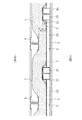
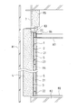
図1は、本発明の実施形態に係る断熱内壁パネルの概略構成を示している。また、図2は、同断熱内壁パネルを施工した内壁構造を水平方向の詳細断面によって示し、図3は、同じく縦方向の概略断面によって示している。 FIG. 1 shows a schematic configuration of a heat insulating inner wall panel according to an embodiment of the present invention. Moreover, FIG. 2 shows the inner wall structure in which the heat insulating inner wall panel is constructed by a detailed cross section in the horizontal direction, and FIG. 3 shows the same by a schematic cross section in the vertical direction.
断熱内壁パネル1は、縦横の桟材を矩形に枠組みして形成した内壁下地枠2と、その屋外側に貼設される防湿シート3と、さらにその屋外側に重ねて貼設される断熱材4とによって構成される。
The heat insulating
内壁下地枠2は、左右一対の縦桟材21、21と、上下一対の横桟材22、22とを枠組みしてなる枠内に、1本乃至数本の中桟材23を接合して形成されている。例示形態において、縦桟材21には、薄板軽量形鋼材からなる矩形閉断面の部材であって、その見込方向の幅が概ね40〜50mm程度の部材が用いられている。また、横桟材22及び中桟材23には、薄板軽量形鋼材からなる矩形断面の部材であって、その見込方向の幅が縦桟材23の略1/2乃至2/3程度である部材が用いられている。縦桟材21、横桟材22及び中桟材23は、それらの屋内側の側面を揃えて枠組みされ、横桟材22及び中桟材23の両端部が、例えば薄鋼板を屈曲形成してなる連結金具24等を介して、縦桟材21の側面に接合されている。ただし、縦桟材21又は横桟材22のいずれか一方に溝形断面の軽量形鋼材を利用し、その溝内に他方の部材の端部を挿入して接合するなどの形態によって内壁下地枠2が形成されてもよい。
The inner
防湿シート3には、例えば、アルミニウム蒸着したポリエチレンフィルムやポリプロピレンフィルム、その他これに類するガス透過性の低い合成樹脂のラミネートフィルムなど、防湿性を有する素材が利用される。その防湿シート3が、上記内壁下地枠2を構成する縦横桟材21、22及び中桟材23の側面に沿うようにして、内壁下地枠2の屋外側全面にわたり貼設される。防湿シート3の貼設手段としては、防湿シート3に穴を開けない両面テープや接着剤等が好適に利用される。
For the moisture-
断熱材4は、例えばグラスウールやロックウール等の断熱性繊維材料をフィルム包装して変形可能にしたものである。包装材料にはポリエチレンフィルム等を利用することができるが、上述した防湿シート3と同じフィルム材料を、少なくとも内壁下地枠2に接する側に用いれば、それ1枚で防湿シート3の機能も兼ねさせることができる。断熱材4の貼設手段としても、両面テープや接着剤等が好適である。
The
内壁下地枠2に貼設される断熱材4の大きさに関しては、高さが、内壁下地枠2の上辺部よりも上方にはみ出して、上側の横桟材22と梁材7との間隙を充分に被覆することができる程度が望ましい。横幅は、少なくとも内壁下地枠2の横幅と同等以上であることが望ましいが、本発明においては、後述するように、内壁下地枠2の割付けが躯体の柱割とは無関係になり、また、断熱材4が躯体と内壁下地枠2との間に途切れることなく連続的に介装されることになるので、断熱材4の横幅と内壁下地枠2の横幅との間に、特に寸法的な関連性を設ける必要はない。
With respect to the size of the
図2において、符号6は鉄骨軸組躯体を構成する柱材である。柱材6は、例えば図示のようなリップ溝形鋼材を2本、背合わせに結合した部材やH形鋼材等によって形成されている。また、図3において、符号7は、躯体を構成する梁材であり、これにはH形鋼等が用いられている。ただし、本発明において躯体を構成する各部材の詳細な断面形状は特に限定しない。
In FIG. 2, the code |
断熱内壁パネル1の施工に際しては、図3に示すように、まず、躯体の外側に外壁パネル81を施工しておき、躯体の内側には床面82を施工しておく。そして、断熱内壁パネル1を床面82上に立設させ、内壁下地枠2の枠内から下辺の横桟材22を床面82にビス打ちするなどして固定する。また、上辺の横桟材22を、適宜の固定金具83等を介して、梁下に固定する。図3に示した固定金具83は、上記特許文献1〜3等に開示された固定金具と同様のもので、詳細な図示は省くが、内壁下地枠2の上辺の横桟材22に上方から嵌装される溝形本体部と、梁材7の下フランジの屋内側縁部に噛み込む固定部とがボルトを介して連結され、ボルトの回動調整によって内壁下地枠2の建ち調整を行うことができる。これ以外の固定手段も、もちろん利用可能である。
When constructing the heat insulating
本発明の要部は、上述した内壁下地枠2の施工に際して、内壁下地枠2を躯体から離隔させるとともに、内壁下地枠2の縦桟材21を躯体の柱材6に対し壁長方向にずらして建て込む点にある。図2に示したように、内壁下地枠2を躯体から間隔Aだけ離し、かつ、内壁下地枠2の縦桟材21と躯体の柱材6とをずらして建て込んだ場合、躯体の柱材6の屋内側には、間隔Aと間隔Bとを合わせたクリアランスが確保される。ここで間隔Bは、内壁下地枠2における縦桟材21と中桟材23との見込寸法の差であり、例示形態では10〜25mm程度を想定している。また、間隔Aについては、20〜30mm程度を想定しており、したがって例示形態の場合、間隔Aと間隔Bとを合わせたクリアランスは30〜55mm程度になる。
The main part of the present invention is that the inner
このようにして躯体の屋内側に形成されるクリアランススペースには、柱材6と内壁下地枠2とを連結する取付金具の類は介在せず、該スペースは上下方向にわたり一様にオープンである。したがって、該スペースには、例えば60〜75mm程度の厚みにフィルム包装された断熱材4を、若干、圧縮して介装することが可能になる。断熱材4は、躯体の柱材6に面しない位置では屋外側に膨出しながら、躯体と内壁下地枠2との間に、途切れなく連続するように配設される。隣接する断熱材4同士は、図示しない適宜箇所で互いに貼着されるが、その継ぎ目の位置は特に制約されない。
In this way, the clearance space formed on the indoor side of the housing does not include any kind of mounting bracket for connecting the
こうして、躯体と内壁下地枠2との間に20〜30mm程度の間隔Aを確保するだけで、そこに、実質的には該間隔Aの2倍又はそれ以上の厚さの断熱材4を配設することが可能になる。しかも、躯体と内壁下地枠2との間には熱橋となり得る部材が介在しないので、壁全体としての断熱性能は飛躍的に向上する。もちろん、躯体と内壁下地枠2との間隔や断熱材4の種類、厚み等を変更することにより、特殊な気象条件の地域にも柔軟に対応することができる。
In this way, only by securing an interval A of about 20 to 30 mm between the housing and the inner
また、内壁下地枠2の建て込みが躯体の柱割に拘束されなくなるので、設計面や施工面での自由度も大きくなる。防湿シート3は内壁下地枠2の屋外側に貼設されているため、内壁下地枠2を床面82上に建て込んで固定する作業や、隣接する内壁下地枠2同士を相互に綴る作業は、屋内側から防湿シート3を破らずに行うことができる。
Moreover, since the erection of the inner
防湿シート3よりも屋内側の枠内領域は、壁内の配線や配管スペースとして利用することも可能であり、それらの工事に際しても防湿シート3を破らずに済む。さらに、該屋内側の枠内領域に、上記断熱材4とは別体の第二の断熱材5を、防湿シート3を挟むようにして追加的に充填することもできる。これによれば断熱性能はさらに向上し、例えば屋内側の冷気によって生じる夏型結露も確実に防止することができる。
The frame area on the indoor side of the moisture-
なお、躯体の隅部等にあっては、柱材6と内壁下地枠2の縦桟材21の位置が揃ってしまい、その間に断熱材4を介装しうるだけの間隙が確保できない、ということも部分的には生じ得る。しかし、そのような特殊部位を除く真っ直ぐな壁面の一般部で、少なくとも躯体や内壁下地枠2の割付け2スパン分以上にわたって、上記のように断熱材4が途切れなく介装される内壁構造を実現することができれば、断熱性能は従来に比して大幅に向上する。
In addition, in the corners of the frame, the positions of the
このようにして躯体の屋内側に断熱内壁パネル1を施工した後は、内壁下地枠2の屋内側の表面に石膏ボード等の内壁下地材や壁紙等の内装仕上材84が施工される。また、梁材7の内側にも断熱材85が介装され、内壁下地枠2の上辺近傍には野縁86や天井パネル87等が施工される。床面82にはフローリング材等の床仕上材88等が貼設される。
After the heat insulation
1 断熱内壁パネル
2 内壁下地枠
21 縦桟材
22 横桟材
23 中桟材
3 防湿シート
4 断熱材
5 第二の断熱材
6 柱材
DESCRIPTION OF
Claims (4)
上記断熱内壁パネル(1)は、軽量形鋼材からなる縦横の桟材を矩形に枠組みして形成した内壁下地枠(2)の屋外側に防湿シート(3)を貼設し、さらにその屋外側にフィルム包装した変形可能な断熱材(4)を貼設したものであり、
上記内壁下地枠(2)が上記躯体から屋内側に離隔して建て込まれるとともに、上記内壁下地枠(2)を構成する縦桟材(21)が上記躯体の柱位置に対し壁長方向にずれて配置され、上記躯体と内壁下地枠(2)との間に上記断熱材(4)が、躯体の柱位置で途切れず壁長方向に連続して介装されることを特徴とする内壁構造。 In the inner wall structure where the heat insulation inner wall panel is built in the indoor side of the steel frame assembly and becomes the inner wall base,
The heat insulating inner wall panel (1) has a moisture-proof sheet (3) attached to the outdoor side of the inner wall base frame (2) formed by vertically and horizontally forming a rectangular frame made of lightweight steel, and the outdoor side thereof A film-wrapped deformable heat insulating material (4) is attached,
The inner wall base frame (2) is built away from the housing on the indoor side, and the vertical bars (21) constituting the inner wall base frame (2) are arranged in the wall length direction with respect to the column position of the housing. An inner wall characterized in that the heat insulating material (4) is arranged in a shifted manner and is continuously interposed in the wall length direction between the housing and the inner wall base frame (2) without being interrupted at the column position of the housing. Construction.
内壁下地枠(2)は、その下辺部及び上辺部が床面(82)や梁下に固定されることにより、躯体から離隔した状態で自立的に保持されることを特徴とする内壁構造。 The inner wall structure according to claim 1,
The inner wall structure is characterized in that the inner wall base frame (2) is held independently in a state of being separated from the frame by fixing the lower side and upper side of the inner wall base frame (2) to the floor (82) or the beam.
内壁下地枠(2)は、左右一対の縦桟材(21、21)と上下一対の横桟材(22、22)とを枠組みしてなる枠内に、上記縦桟材(21)よりも小幅の中桟材(23)が、上記縦桟材(21)と屋内側の側面を揃えて接合されてなり、上記縦横桟材(21、22)及び中桟材(23)の屋外側の側面に沿って防湿シート(3)が貼設されていることを特徴とする内壁構造。 The inner wall structure according to claim 1 or 2,
The inner wall base frame (2) has a frame formed by framing a pair of left and right vertical bars (21, 21) and a pair of upper and lower horizontal bars (22, 22) than the vertical bars (21). A narrow medium beam member (23) is joined to the vertical beam member (21) so that the side surfaces on the indoor side are aligned, and on the outdoor side of the vertical and horizontal beam members (21, 22) and the intermediate beam member (23). A moisture barrier sheet (3) is stuck along the side surface.
防湿シート(3)よりも屋内側に位置する内壁下地枠(2)の枠内領域に、第二の断熱材(5)が充填されたことを特徴とする内壁構造。 In the inner wall structure as described in any one of Claims 1-3,
An inner wall structure characterized in that a second heat insulating material (5) is filled in an in-frame region of an inner wall base frame (2) located on the indoor side of the moisture-proof sheet (3).
Priority Applications (1)
| Application Number | Priority Date | Filing Date | Title |
|---|---|---|---|
| JP2008204320A JP5239603B2 (en) | 2008-08-07 | 2008-08-07 | Inner wall structure |
Applications Claiming Priority (1)
| Application Number | Priority Date | Filing Date | Title |
|---|---|---|---|
| JP2008204320A JP5239603B2 (en) | 2008-08-07 | 2008-08-07 | Inner wall structure |
Publications (2)
| Publication Number | Publication Date |
|---|---|
| JP2010037873A true JP2010037873A (en) | 2010-02-18 |
| JP5239603B2 JP5239603B2 (en) | 2013-07-17 |
Family
ID=42010701
Family Applications (1)
| Application Number | Title | Priority Date | Filing Date |
|---|---|---|---|
| JP2008204320A Expired - Fee Related JP5239603B2 (en) | 2008-08-07 | 2008-08-07 | Inner wall structure |
Country Status (1)
| Country | Link |
|---|---|
| JP (1) | JP5239603B2 (en) |
Cited By (8)
| Publication number | Priority date | Publication date | Assignee | Title |
|---|---|---|---|---|
| JP2012172393A (en) * | 2011-02-22 | 2012-09-10 | Toyota Home Kk | Thermal insulation structure of building |
| JP2012202163A (en) * | 2011-03-28 | 2012-10-22 | Toyota Home Kk | Inner wall panel installation structure in building |
| CN104032866A (en) * | 2014-05-20 | 2014-09-10 | 浙江亚厦装饰股份有限公司 | Light steel keel |
| CN105201231A (en) * | 2015-09-24 | 2015-12-30 | 张家港市盛港绿色防火建材有限公司 | Fireproof heat-insulating container house |
| CN105201229A (en) * | 2015-09-24 | 2015-12-30 | 张家港市盛港绿色防火建材有限公司 | Container room with improved stand column structure |
| CN105201102A (en) * | 2015-09-24 | 2015-12-30 | 张家港市盛港绿色防火建材有限公司 | Combined spliced and inserted type container house wall |
| JP2017025523A (en) * | 2015-07-17 | 2017-02-02 | 旭化成ホームズ株式会社 | Outer peripheral wall structure of building and repair method for outer peripheral wall of building |
| CN107419869A (en) * | 2017-05-11 | 2017-12-01 | 深圳海外装饰工程有限公司 | The installation method and mounting structure of shingle nail |
Citations (7)
| Publication number | Priority date | Publication date | Assignee | Title |
|---|---|---|---|---|
| JPH09125550A (en) * | 1995-10-31 | 1997-05-13 | San Utsudo Niigata:Kk | Building and its external wall structural body |
| JPH10231565A (en) * | 1997-02-20 | 1998-09-02 | Yamaha Corp | Sound insulating panel |
| JPH10237976A (en) * | 1997-03-03 | 1998-09-08 | Sekisui House Ltd | Heat insulation inner wall panel |
| JPH10266417A (en) * | 1997-03-26 | 1998-10-06 | Sekisui House Ltd | Structure for constructing heat insulating interior wall panel |
| JPH10280584A (en) * | 1997-04-03 | 1998-10-20 | Sekisui House Ltd | Heat insulation interior wall panel |
| JP2001003470A (en) * | 1999-06-25 | 2001-01-09 | Sekisui Chem Co Ltd | Thermal insulating structure of building |
| JP2001049767A (en) * | 1999-08-05 | 2001-02-20 | Sekisui House Ltd | Side part fixing hardware of metallic heat insulating inner wall frame |
-
2008
- 2008-08-07 JP JP2008204320A patent/JP5239603B2/en not_active Expired - Fee Related
Patent Citations (7)
| Publication number | Priority date | Publication date | Assignee | Title |
|---|---|---|---|---|
| JPH09125550A (en) * | 1995-10-31 | 1997-05-13 | San Utsudo Niigata:Kk | Building and its external wall structural body |
| JPH10231565A (en) * | 1997-02-20 | 1998-09-02 | Yamaha Corp | Sound insulating panel |
| JPH10237976A (en) * | 1997-03-03 | 1998-09-08 | Sekisui House Ltd | Heat insulation inner wall panel |
| JPH10266417A (en) * | 1997-03-26 | 1998-10-06 | Sekisui House Ltd | Structure for constructing heat insulating interior wall panel |
| JPH10280584A (en) * | 1997-04-03 | 1998-10-20 | Sekisui House Ltd | Heat insulation interior wall panel |
| JP2001003470A (en) * | 1999-06-25 | 2001-01-09 | Sekisui Chem Co Ltd | Thermal insulating structure of building |
| JP2001049767A (en) * | 1999-08-05 | 2001-02-20 | Sekisui House Ltd | Side part fixing hardware of metallic heat insulating inner wall frame |
Cited By (8)
| Publication number | Priority date | Publication date | Assignee | Title |
|---|---|---|---|---|
| JP2012172393A (en) * | 2011-02-22 | 2012-09-10 | Toyota Home Kk | Thermal insulation structure of building |
| JP2012202163A (en) * | 2011-03-28 | 2012-10-22 | Toyota Home Kk | Inner wall panel installation structure in building |
| CN104032866A (en) * | 2014-05-20 | 2014-09-10 | 浙江亚厦装饰股份有限公司 | Light steel keel |
| JP2017025523A (en) * | 2015-07-17 | 2017-02-02 | 旭化成ホームズ株式会社 | Outer peripheral wall structure of building and repair method for outer peripheral wall of building |
| CN105201231A (en) * | 2015-09-24 | 2015-12-30 | 张家港市盛港绿色防火建材有限公司 | Fireproof heat-insulating container house |
| CN105201229A (en) * | 2015-09-24 | 2015-12-30 | 张家港市盛港绿色防火建材有限公司 | Container room with improved stand column structure |
| CN105201102A (en) * | 2015-09-24 | 2015-12-30 | 张家港市盛港绿色防火建材有限公司 | Combined spliced and inserted type container house wall |
| CN107419869A (en) * | 2017-05-11 | 2017-12-01 | 深圳海外装饰工程有限公司 | The installation method and mounting structure of shingle nail |
Also Published As
| Publication number | Publication date |
|---|---|
| JP5239603B2 (en) | 2013-07-17 |
Similar Documents
| Publication | Publication Date | Title |
|---|---|---|
| JP5239603B2 (en) | Inner wall structure | |
| KR101065036B1 (en) | Double insulated curtain wall with variable groove for glass | |
| GB2481126A (en) | Multi panel wall system with reinforced panel joints | |
| KR101072957B1 (en) | Curtain wall system with high insulation | |
| KR102209026B1 (en) | Curtain wall insulation system | |
| KR20120028478A (en) | Steel-aluminium combination type unitized curtain wall | |
| KR101173795B1 (en) | Assemblable Truss Structure | |
| CN102472042A (en) | A building assembly with a corner profile for an insulating building system | |
| JP3762656B2 (en) | Glass curtain wall | |
| CN203795652U (en) | Combination wall | |
| KR100959063B1 (en) | apparatus for reinforcing frame of curtain wall and window system | |
| CN104769195A (en) | Combined wall body and construction method thereof | |
| KR100996657B1 (en) | Multi-layer glass assembly | |
| JP2007308906A (en) | Exterior wall of building, and curtain wall | |
| KR20110009307A (en) | Guard track for insulating panel and install structure of insulating panel using guard track | |
| KR102288043B1 (en) | Non exposed curtain wall system | |
| WO2010106224A1 (en) | Wall element | |
| KR100533354B1 (en) | A Structure for Liner Panel using of Roof | |
| KR102085965B1 (en) | Sound proof tunnel and construction method thereof | |
| CN210713418U (en) | Curved surface glass curtain wall mounting structure | |
| KR101673418B1 (en) | Open joint curtain wall complex external pannel assembly unit used in building construction | |
| JP4904460B2 (en) | curtain wall | |
| KR20130048987A (en) | Structural panel and assembling structure for structural panels using bracket | |
| KR20170072383A (en) | Semi-unit curtain wall and construction method of the same | |
| JP4293896B2 (en) | Airtight insulation structure around the outer wall opening |
Legal Events
| Date | Code | Title | Description |
|---|---|---|---|
| A621 | Written request for application examination |
Free format text: JAPANESE INTERMEDIATE CODE: A621 Effective date: 20101006 |
|
| A977 | Report on retrieval |
Free format text: JAPANESE INTERMEDIATE CODE: A971007 Effective date: 20120514 |
|
| A131 | Notification of reasons for refusal |
Free format text: JAPANESE INTERMEDIATE CODE: A131 Effective date: 20120522 |
|
| TRDD | Decision of grant or rejection written | ||
| A01 | Written decision to grant a patent or to grant a registration (utility model) |
Free format text: JAPANESE INTERMEDIATE CODE: A01 Effective date: 20130305 |
|
| A61 | First payment of annual fees (during grant procedure) |
Free format text: JAPANESE INTERMEDIATE CODE: A61 Effective date: 20130318 |
|
| FPAY | Renewal fee payment (event date is renewal date of database) |
Free format text: PAYMENT UNTIL: 20160412 Year of fee payment: 3 |
|
| R150 | Certificate of patent or registration of utility model |
Free format text: JAPANESE INTERMEDIATE CODE: R150 |
|
| LAPS | Cancellation because of no payment of annual fees |