JP2010037764A - ガス圧接用鉄筋保持装置 - Google Patents
ガス圧接用鉄筋保持装置 Download PDFInfo
- Publication number
- JP2010037764A JP2010037764A JP2008200145A JP2008200145A JP2010037764A JP 2010037764 A JP2010037764 A JP 2010037764A JP 2008200145 A JP2008200145 A JP 2008200145A JP 2008200145 A JP2008200145 A JP 2008200145A JP 2010037764 A JP2010037764 A JP 2010037764A
- Authority
- JP
- Japan
- Prior art keywords
- reinforcing bar
- tubular member
- gripping device
- diameter tubular
- pressure welding
- Prior art date
- Legal status (The legal status is an assumption and is not a legal conclusion. Google has not performed a legal analysis and makes no representation as to the accuracy of the status listed.)
- Granted
Links
- 238000003466 welding Methods 0.000 title claims abstract description 47
- 230000002787 reinforcement Effects 0.000 title 1
- 230000003014 reinforcing effect Effects 0.000 claims abstract description 236
- 238000003825 pressing Methods 0.000 claims description 25
- 230000002265 prevention Effects 0.000 claims description 2
- 238000000034 method Methods 0.000 description 5
- 230000002093 peripheral effect Effects 0.000 description 5
- 229910000831 Steel Inorganic materials 0.000 description 4
- 239000010959 steel Substances 0.000 description 4
- 230000000903 blocking effect Effects 0.000 description 3
- 239000004567 concrete Substances 0.000 description 2
- 238000010276 construction Methods 0.000 description 1
- 238000010438 heat treatment Methods 0.000 description 1
- 230000000149 penetrating effect Effects 0.000 description 1
- 239000011150 reinforced concrete Substances 0.000 description 1
Images


Landscapes
- Pressure Welding/Diffusion-Bonding (AREA)
- Butt Welding And Welding Of Specific Article (AREA)
Abstract
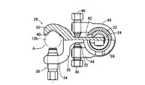
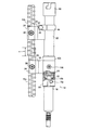
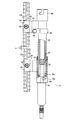
【解決手段】大径スリーブ22は、油圧シリンダ16を装着するための第1装着装置84および第2装着装置86を両端部にそれぞれ備え、第1鉄筋把持装置26は、軸心Jまわりの相対回転可能且つ軸方向の移動不能に大径スリーブ22の一端部に設けられていることから、一対の鉄筋12aおよび12bの端部の端面の軸心が一致しない場合でも、第1鉄筋把持装置26および第2鉄筋把持装置28は容易に一対の鉄筋12aおよび12bの端部を把持することができ、次いで第1鉄筋把持装置26を大径スリーブ22の一端部に対して相対回転させることによりその一対の鉄筋12aおよび12bの端部の軸心を能率よく容易に一致させることができる。
【選択図】図1
Description
12a:鉄筋、12b:鉄筋
16:油圧シリンダ(押圧シリンダ)
22:大径スリーブ(大径管状部材)
24:小径スリーブ(小径管状部材)
26:第1鉄筋把持装置
28:第2鉄筋把持装置
42:切欠き
84:第1装着装置
86:第2装着装置
106:回転止めボルト(相対回転阻止装置)
Claims (6)
- 大径管状部材と、該大径管状部材内に軸心方向の相対移動可能且つ軸心回りの相対回転不能に嵌め入れられた小径管状部材と、該大径管状部材の一端部に設けられて一方の鉄筋を把持するための第1鉄筋把持装置と、小径管状部材に一体的に固設されて他方の鉄筋を把持するための第2鉄筋把持装置とを備え、該第1鉄筋把持装置により把持された一方の鉄筋と該第2鉄筋把持装置により把持された他方の鉄筋とを相互に突き合わせた状態で前記大径管状部材の他端部に装着された押圧シリンダが前記小径管状部材を軸心方向へ駆動することにより、ガス圧に際して該一方の鉄筋および他方の鉄筋を相互に圧接状態で固定するガス圧接用鉄筋保持装置であって、
前記大径管状部材は、前記押圧シリンダを装着するための装着装置を両端部にそれぞれ備え、
前記第1鉄筋把持装置は、軸心まわりの相対回転可能且つ軸方向の移動不能に前記大径管状部材の一端部に設けられている
ことを特徴とするガス圧接用鉄筋保持装置。 - 前記第1鉄筋把持装置と前記大径管状部材の相対回転を阻止するために操作される相対回転阻止装置を、さらに備える
ことを特徴とする請求項1のガス圧接用鉄筋保持装置。 - 前記第2鉄筋把持装置は前記小径管状部材の他端部に固定され、
前記大径管状部材には、該第2鉄筋把持装置を厚み方向に貫通させ且つ軸心方向へ案内するガイドスリットが他端部に形成されている
ことを特徴とする請求項1または2のガス圧接用鉄筋保持装置。 - 前記大径管状部材の軸心と前記第1鉄筋把持装置および第2鉄筋把持装置により把持された一方および他方の鉄筋の軸心とは互いに平行となるように設定されていることを特徴とする請求項1乃至3のいずれか1のガス圧接用鉄筋保持装置。
- 前記第1鉄筋把持装置により把持された一方の鉄筋と該第2鉄筋把持装置により把持された他方の鉄筋とは、前記大径管状部材の一端部に装着された押圧シリンダが前記小径管状部材を軸心方向へ駆動することにより、相互に離隔させられることを特徴とする請求項1乃至4のいずれか1のガス圧接用鉄筋保持装置。
- 前記第1鉄筋把持装置により把持された一方の鉄筋と該第2鉄筋把持装置により把持された他方の鉄筋とは、前記大径管状部材の一端部に装着された押圧シリンダが前記小径管状部材を軸心方向へ駆動することにより相互に離隔させられた状態で、前記第1鉄筋把持装置が前記大径管状部材に対して相対回転させられることにより、相互に芯出しが行われることを特徴とする請求項1乃至5のいずれか1のガス圧接用鉄筋保持装置。
Priority Applications (1)
| Application Number | Priority Date | Filing Date | Title |
|---|---|---|---|
| JP2008200145A JP4746652B2 (ja) | 2008-08-01 | 2008-08-01 | ガス圧接用鉄筋保持装置 |
Applications Claiming Priority (1)
| Application Number | Priority Date | Filing Date | Title |
|---|---|---|---|
| JP2008200145A JP4746652B2 (ja) | 2008-08-01 | 2008-08-01 | ガス圧接用鉄筋保持装置 |
Publications (2)
| Publication Number | Publication Date |
|---|---|
| JP2010037764A true JP2010037764A (ja) | 2010-02-18 |
| JP4746652B2 JP4746652B2 (ja) | 2011-08-10 |
Family
ID=42010596
Family Applications (1)
| Application Number | Title | Priority Date | Filing Date |
|---|---|---|---|
| JP2008200145A Active JP4746652B2 (ja) | 2008-08-01 | 2008-08-01 | ガス圧接用鉄筋保持装置 |
Country Status (1)
| Country | Link |
|---|---|
| JP (1) | JP4746652B2 (ja) |
Cited By (3)
| Publication number | Priority date | Publication date | Assignee | Title |
|---|---|---|---|---|
| JP2013130017A (ja) * | 2011-12-21 | 2013-07-04 | Daia Co Ltd | 鉄筋固定装置 |
| CN114704100A (zh) * | 2022-03-24 | 2022-07-05 | 中建八局第一建设有限公司 | 一种高强拉杆张拉工装及使用方法 |
| CN117548887A (zh) * | 2024-01-11 | 2024-02-13 | 潍坊昌大建设集团有限公司 | 钢筋焊接定位装置 |
Citations (2)
| Publication number | Priority date | Publication date | Assignee | Title |
|---|---|---|---|---|
| JPH02255294A (ja) * | 1989-03-28 | 1990-10-16 | Kobe Steel Ltd | 溶接用位置調整装置 |
| JP3498046B2 (ja) * | 2000-07-04 | 2004-02-16 | 株式会社ダイア | 鉄筋固定装置 |
-
2008
- 2008-08-01 JP JP2008200145A patent/JP4746652B2/ja active Active
Patent Citations (2)
| Publication number | Priority date | Publication date | Assignee | Title |
|---|---|---|---|---|
| JPH02255294A (ja) * | 1989-03-28 | 1990-10-16 | Kobe Steel Ltd | 溶接用位置調整装置 |
| JP3498046B2 (ja) * | 2000-07-04 | 2004-02-16 | 株式会社ダイア | 鉄筋固定装置 |
Cited By (5)
| Publication number | Priority date | Publication date | Assignee | Title |
|---|---|---|---|---|
| JP2013130017A (ja) * | 2011-12-21 | 2013-07-04 | Daia Co Ltd | 鉄筋固定装置 |
| CN114704100A (zh) * | 2022-03-24 | 2022-07-05 | 中建八局第一建设有限公司 | 一种高强拉杆张拉工装及使用方法 |
| CN114704100B (zh) * | 2022-03-24 | 2023-06-20 | 中建八局第一建设有限公司 | 一种高强拉杆张拉工装及使用方法 |
| CN117548887A (zh) * | 2024-01-11 | 2024-02-13 | 潍坊昌大建设集团有限公司 | 钢筋焊接定位装置 |
| CN117548887B (zh) * | 2024-01-11 | 2024-04-02 | 潍坊昌大建设集团有限公司 | 钢筋焊接定位装置 |
Also Published As
| Publication number | Publication date |
|---|---|
| JP4746652B2 (ja) | 2011-08-10 |
Similar Documents
| Publication | Publication Date | Title |
|---|---|---|
| US20140227024A1 (en) | Assembly for connecting rebar segments | |
| US9511488B2 (en) | King pin removal tool | |
| US12044010B2 (en) | Rebar movement-prevention-type one-touch coupler | |
| CA2920279A1 (en) | Anchor bolt | |
| JP4746652B2 (ja) | ガス圧接用鉄筋保持装置 | |
| CA2816439C (en) | Method and device for locking a support ring to a scaffolding column | |
| JP3146837U (ja) | ガス圧接用鉄筋保持装置 | |
| JP2000234333A (ja) | 鋼管矢板等の縦継ぎ装置 | |
| JP2826269B2 (ja) | ワンサイドボルト使用柱・梁接合構造 | |
| WO2019008146A1 (en) | APPARATUS FOR THE REMOVAL OF A CIRCULAR COLLAR MOUNTED BY BINDING ON A CYLINDRICAL SURFACE | |
| JP2016211302A (ja) | ガス圧接用鉄筋保持装置 | |
| CN117248520B (zh) | 灌注桩钢筋笼快速定位的辅助装置 | |
| JP2702887B2 (ja) | ワンサイドボルト使用角形鋼管柱接合方法および接合構造 | |
| JP5618601B2 (ja) | ガス圧接用鉄筋保持装置 | |
| JPH02212078A (ja) | インサートの取付けスウェージ工具 | |
| JP4792506B2 (ja) | 削岩時の方法及び装置 | |
| KR20140075833A (ko) | 전단응력 집중형 티에스 커플러 | |
| JP7282641B2 (ja) | 鉄筋用圧接治具 | |
| JP7514537B2 (ja) | パイプ脱着具 | |
| JP3619170B2 (ja) | 鉄骨建入直し調整治具 | |
| KR20140042069A (ko) | 체결 가이드가 형성된 스패너 | |
| JP4580961B2 (ja) | 鉄筋固定装置 | |
| JP6923143B2 (ja) | 鋼管用継手 | |
| JP2021075920A (ja) | Pc鋼材の緊張力調整治具およびpc鋼材の緊張力調整方法 | |
| KR101144138B1 (ko) | 양방향 자동체결장치 및 이를 이용한 부재의 양방향 자동 체결방법 |
Legal Events
| Date | Code | Title | Description |
|---|---|---|---|
| A977 | Report on retrieval |
Free format text: JAPANESE INTERMEDIATE CODE: A971007 Effective date: 20110214 |
|
| A131 | Notification of reasons for refusal |
Free format text: JAPANESE INTERMEDIATE CODE: A131 Effective date: 20110222 |
|
| A521 | Request for written amendment filed |
Free format text: JAPANESE INTERMEDIATE CODE: A523 Effective date: 20110329 |
|
| TRDD | Decision of grant or rejection written | ||
| A01 | Written decision to grant a patent or to grant a registration (utility model) |
Free format text: JAPANESE INTERMEDIATE CODE: A01 Effective date: 20110426 |
|
| A01 | Written decision to grant a patent or to grant a registration (utility model) |
Free format text: JAPANESE INTERMEDIATE CODE: A01 |
|
| A61 | First payment of annual fees (during grant procedure) |
Free format text: JAPANESE INTERMEDIATE CODE: A61 Effective date: 20110513 |
|
| FPAY | Renewal fee payment (event date is renewal date of database) |
Free format text: PAYMENT UNTIL: 20140520 Year of fee payment: 3 |
|
| R150 | Certificate of patent or registration of utility model |
Ref document number: 4746652 Country of ref document: JP Free format text: JAPANESE INTERMEDIATE CODE: R150 Free format text: JAPANESE INTERMEDIATE CODE: R150 |
|
| R250 | Receipt of annual fees |
Free format text: JAPANESE INTERMEDIATE CODE: R250 |
|
| R250 | Receipt of annual fees |
Free format text: JAPANESE INTERMEDIATE CODE: R250 |
|
| R250 | Receipt of annual fees |
Free format text: JAPANESE INTERMEDIATE CODE: R250 |
|
| R250 | Receipt of annual fees |
Free format text: JAPANESE INTERMEDIATE CODE: R250 |
|
| R250 | Receipt of annual fees |
Free format text: JAPANESE INTERMEDIATE CODE: R250 |
|
| R250 | Receipt of annual fees |
Free format text: JAPANESE INTERMEDIATE CODE: R250 |
|
| R250 | Receipt of annual fees |
Free format text: JAPANESE INTERMEDIATE CODE: R250 |
|
| R250 | Receipt of annual fees |
Free format text: JAPANESE INTERMEDIATE CODE: R250 |
|
| R250 | Receipt of annual fees |
Free format text: JAPANESE INTERMEDIATE CODE: R250 |
|
| R250 | Receipt of annual fees |
Free format text: JAPANESE INTERMEDIATE CODE: R250 |
|
| R250 | Receipt of annual fees |
Free format text: JAPANESE INTERMEDIATE CODE: R250 |
|
| R250 | Receipt of annual fees |
Free format text: JAPANESE INTERMEDIATE CODE: R250 |