JP2010037764A - Reinforcement holding device for gas pressure welding - Google Patents
Reinforcement holding device for gas pressure welding Download PDFInfo
- Publication number
- JP2010037764A JP2010037764A JP2008200145A JP2008200145A JP2010037764A JP 2010037764 A JP2010037764 A JP 2010037764A JP 2008200145 A JP2008200145 A JP 2008200145A JP 2008200145 A JP2008200145 A JP 2008200145A JP 2010037764 A JP2010037764 A JP 2010037764A
- Authority
- JP
- Japan
- Prior art keywords
- reinforcing bar
- tubular member
- gripping device
- diameter tubular
- pressure welding
- Prior art date
- Legal status (The legal status is an assumption and is not a legal conclusion. Google has not performed a legal analysis and makes no representation as to the accuracy of the status listed.)
- Granted
Links
- 238000003466 welding Methods 0.000 title claims abstract description 47
- 230000002787 reinforcement Effects 0.000 title abstract 11
- 230000003014 reinforcing effect Effects 0.000 claims description 228
- 238000003825 pressing Methods 0.000 claims description 25
- 230000002265 prevention Effects 0.000 claims description 2
- 238000000034 method Methods 0.000 description 5
- 230000002093 peripheral effect Effects 0.000 description 5
- 229910000831 Steel Inorganic materials 0.000 description 4
- 239000010959 steel Substances 0.000 description 4
- 230000000903 blocking effect Effects 0.000 description 3
- 239000004567 concrete Substances 0.000 description 2
- 238000010276 construction Methods 0.000 description 1
- 238000010438 heat treatment Methods 0.000 description 1
- 230000000149 penetrating effect Effects 0.000 description 1
- 239000011150 reinforced concrete Substances 0.000 description 1
Images


Landscapes
- Pressure Welding/Diffusion-Bonding (AREA)
- Butt Welding And Welding Of Specific Article (AREA)
Abstract
Description
本発明は、ガス圧接に際して一対の鉄筋を相互に突き合わせた保持するためのガス圧接用鉄筋保持装置に関するものである。 The present invention relates to a reinforcing bar holding device for gas pressure welding for holding a pair of reinforcing bars butted against each other during gas pressure welding.
例えば、RC構造、SRC構造の建築物において、鉄筋コンクリートを施工するに先立って、コンクリートに埋設される鉄筋を長手方向へ相互に接続する必要がある。このため、たとえば特許文献1に記載されるように、ガス圧接に際して一対の鉄筋の両端部を突き合わせた状態で固定するガス圧接用鉄筋保持装置が提案されている。このようなガス圧接用鉄筋保持装置によれば、一対の鉄筋の相互に突き当てられた端部を赤熱した状態で大径の膨出部が形成されるまで押圧しこの状態を保持して接合するガス圧接を行うために、その一対の鉄筋の端部が相互に突き合わせた状態で固定される。 For example, in a building having an RC structure or an SRC structure, it is necessary to connect the reinforcing bars embedded in the concrete in the longitudinal direction before constructing the reinforced concrete. For this reason, as described in Patent Document 1, for example, there is proposed a gas pressure welding reinforcing bar holding device that fixes both ends of a pair of reinforcing bars in a state of abutting against each other at the time of gas pressure welding. According to such a rebar holding device for gas pressure welding, the end portions of the pair of rebars pressed against each other are pressed until a large-diameter bulging portion is formed in a red-hot state, and this state is held and joined. In order to perform gas pressure welding, the ends of the pair of reinforcing bars are fixed in a state where they abut each other.
建築現場では、上記ガス圧接用鉄筋保持装置を用いてガス圧接することにより複数本の鉄筋(主筋)をそれぞれ延長し、次いで、それらに直交するように配設された他の鉄筋たとえば四角枠状のフープ筋に対して1本ずつ針金を用いて相互に固縛することにより、柱や梁に対応した寸法のかご状となるように複数本の鉄筋が所定間隔で組み立てられている。 At a construction site, a plurality of reinforcing bars (main reinforcing bars) are respectively extended by gas pressure welding using the above-mentioned gas pressure welding reinforcing bar holding device, and then another reinforcing bar arranged perpendicular to them, for example, in the form of a square frame A plurality of reinforcing bars are assembled at predetermined intervals so as to form a cage shape corresponding to a column or a beam by securing them to the hoop bars one by one using a wire.
これに対して、一層、機械施行の割合を高めて作業員数および作業範囲を少なくするために、柱や梁に応じた形状となるように複数本の鉄筋(主筋)をかご状の鉄筋ユニットとなるように、フープ筋および針金を用いて別の作業場所で予め先組みし、次いでそのかご状の鉄筋ユニットを、鉄骨の組み立てと同様に、クレーンにて所定の位置へ移動させた状態で、既に配設されてたとえばコンクリートから突き出している複数本の鉄筋との間で、ガス圧接により鉄筋の接続を行う施行方法が行われている。
ところで、上記のように、先組みされたかご状の鉄筋ユニットの複数本の鉄筋(主筋)を、既に配設された複数本の鉄筋(主筋)とそれぞれ接合するに際しては、従来と同様に、ガス圧接用鉄筋保持装置を用いて一対の鉄筋の相互に突き当てられた状態で固定し、それら一対の鉄筋の端部を赤熱した状態で大径の膨出部が形成されるまで押圧しこの状態を保持して接合するガス圧接が、それぞれ行われる。しかしながら、かご状の鉄筋ユニットの複数本の鉄筋(主筋)の端部と既に配設された複数本の鉄筋(主筋)の端部との間では、それらの端面の軸心方向の位置および軸心が必ずしもそれぞれ一致せず、軸心方向位置が重なるものもある。このため、前記従来のガス圧接用鉄筋保持装置を用いて一対の鉄筋の端部を相互に突き合わせた状態でそれぞれ固定しようとすることが困難となり、作業性が大幅に低下するという不都合があった。 By the way, as described above, when joining a plurality of reinforcing bars (main reinforcing bars) of a basket-shaped reinforcing bar unit assembled in advance to a plurality of reinforcing bars (main reinforcing bars) already arranged, Using a rebar holding device for gas pressure welding, fix the pair of rebars against each other and press the end of the pair of rebars until the large-diameter bulge is formed in a red-hot state. Gas pressure welding for maintaining the state and joining is performed. However, between the ends of the multiple reinforcing bars (main reinforcing bars) of the cage-shaped reinforcing bar unit and the ends of the multiple reinforcing bars (main reinforcing bars) that have already been arranged, the axial positions and axes of those end faces In some cases, the centers do not necessarily coincide with each other, and the axial positions overlap. For this reason, it becomes difficult to try to fix the ends of a pair of reinforcing bars in a state where they are in contact with each other using the conventional gas pressure welding reinforcing bar holding device, and the workability is greatly reduced. .
本発明は、以上の事情を背景として為されたものであって、その目的とするところは、一対の鉄筋の端部の端面の軸心が一致せず、軸心方向位置が重なったとしても、能率よくそれら一対の鉄筋の端部を互いに突き合わせた状態で固定することができるガス圧接用鉄筋保持装置を提供することにある。 The present invention has been made in the background of the above circumstances, and the purpose of the present invention is that even if the axial centers of the end surfaces of the pair of reinforcing bars do not coincide with each other and the axial positions overlap. An object of the present invention is to provide a reinforcing bar holding device for gas pressure welding that can efficiently fix the ends of a pair of reinforcing bars in a state of abutting each other.
斯かる目的を達成するための請求項1に係る発明の要旨とするところは、(a)大径管状部材と、該大径管状部材内に軸心方向の相対移動可能且つ軸心回りの相対回転不能に嵌め入れられた小径管状部材と、該大径管状部材の一端部に設けられて一方の鉄筋を把持するための第1鉄筋把持装置と、小径管状部材に一体的に固設されて他方の鉄筋を把持するための第2鉄筋把持装置とを備え、該第1鉄筋把持装置により把持された一方の鉄筋と該第2鉄筋把持装置により把持された他方の鉄筋とを相互に突き合わせた状態で前記大径管状部材の他端部に装着された押圧シリンダが前記小径管状部材を軸心方向へ駆動することにより、該一方の鉄筋および他方の鉄筋を相互に圧接状態で固定するガス圧接用鉄筋保持装置であって、(b)前記大径管状部材は、前記押圧シリンダを装着するための装着装置を両端部にそれぞれ備え、(c)前記第1鉄筋把持装置は、軸心まわりの相対回転可能且つ軸方向の移動不能に前記大径管状部材の一端部に設けられていることにある。 The gist of the invention according to claim 1 for achieving such an object is as follows: (a) a large-diameter tubular member, and a relative movement around the axial center that is relatively movable in the axial direction in the large-diameter tubular member. A small-diameter tubular member fitted in a non-rotatable manner, a first rebar-gripping device provided at one end of the large-diameter tubular member for grasping one rebar, and a small-diameter tubular member fixed integrally. A second reinforcing bar gripping device for gripping the other reinforcing bar, and the one reinforcing bar gripped by the first reinforcing bar gripping device and the other reinforcing bar gripped by the second reinforcing bar gripping device are mutually butted In this state, a pressing cylinder mounted on the other end of the large-diameter tubular member drives the small-diameter tubular member in the axial direction to fix the one reinforcing bar and the other reinforcing bar in a pressure-contact state with each other. Reinforcing bar holding device, (b) said large diameter Each of the members has a mounting device for mounting the pressing cylinder at both ends, and (c) the first rebar gripping device is a large-diameter tubular member that is relatively rotatable about an axis and immovable in the axial direction. It exists in the one end part of a member.
また、請求項2に係る発明の要旨とするところは、請求項1に係る発明において、(d)前記第1鉄筋把持装置と前記大径管状部材の相対回転を阻止するために操作される相対回転阻止装置を、さらに備えることにある。 A gist of the invention according to claim 2 is that, in the invention according to claim 1, (d) a relative operated to prevent relative rotation between the first reinforcing bar gripping device and the large-diameter tubular member. The object is to further include a rotation preventing device.
また、請求項3に係る発明の要旨とするところは、請求項1または2に係る発明において、(e)前記第2鉄筋把持装置は前記小径管状部材の他端部に固定され、(f)前記大径管状部材には、該第2鉄筋把持装置を厚み方向に貫通させ且つ軸心方向へ案内するガイドスリットが他端部に形成されていることにある。 The gist of the invention according to claim 3 is that, in the invention according to claim 1 or 2, (e) the second rebar gripping device is fixed to the other end of the small-diameter tubular member, and (f) The large-diameter tubular member is formed with a guide slit formed at the other end so as to penetrate the second reinforcing bar gripping device in the thickness direction and guide it in the axial direction.
また、請求項4に係る発明の要旨とするところは、請求項1乃至3のいずれか1に係る発明において、(g)前記大径管状部材の軸心と前記第1鉄筋把持装置および第2鉄筋把持装置により把持された一方および他方の鉄筋の軸心とは互いに平行となるように設定されていることにある。 Further, the gist of the invention according to claim 4 is that, in the invention according to any one of claims 1 to 3, (g) the axis of the large-diameter tubular member, the first rebar gripping device, and the second The reason is that the axes of one and the other reinforcing bars gripped by the reinforcing bar gripping device are set to be parallel to each other.
また、請求項5に係る発明の要旨とするところは、請求項1乃至4のいずれか1に係る発明において、(h)前記第1鉄筋把持装置により把持された一方の鉄筋と前記第2鉄筋把持装置により把持された他方の鉄筋とは、前記大径管状部材の一端部に装着された押圧シリンダが前記小径管状部材を軸心方向へ駆動することにより、相互に離隔させられることにある。 Moreover, the gist of the invention according to claim 5 is that, in the invention according to any one of claims 1 to 4, (h) one reinforcing bar gripped by the first reinforcing bar gripping device and the second reinforcing bar. The other reinforcing bar gripped by the gripping device is that the pressing cylinder attached to one end of the large-diameter tubular member is separated from each other by driving the small-diameter tubular member in the axial direction.
また、請求項6に係る発明の要旨とするところは、請求項1乃至5のいずれか1に係る発明において、(i)前記第1鉄筋把持装置により把持された一方の鉄筋と該第2鉄筋把持装置により把持された他方の鉄筋とは、前記大径管状部材の一端部に装着された押圧シリンダが前記小径管状部材を軸心方向へ駆動することにより相互に離隔させられた状態で、前記第1鉄筋把持装置が前記大径管状部材に対して相対回転させられることにより、相互に芯出しが行われることにある。 A gist of the invention according to claim 6 is that, in the invention according to any one of claims 1 to 5, (i) one reinforcing bar gripped by the first reinforcing bar gripping device and the second reinforcing bar. The other reinforcing bar gripped by the gripping device is a state in which the pressing cylinder attached to one end of the large-diameter tubular member is separated from each other by driving the small-diameter tubular member in the axial direction. The first reinforcing bar gripping device is centered on each other by being rotated relative to the large-diameter tubular member.
請求項1に係る発明のガス圧接用鉄筋保持装置によれば、前記大径管状部材は、前記押圧シリンダを装着するための装着装置を両端部にそれぞれ備え、前記第1鉄筋把持装置は、軸心まわりの相対回転可能且つ軸方向の移動不能に前記大径管状部材の一端部に設けられていることから、一対の鉄筋の端部の端面の軸心が一致しない場合でも、第1鉄筋把持装置および第2鉄筋把持装置は容易に一対の鉄筋の端部を把持することができ、次いで第1鉄筋把持装置を大径管状部材の一端部に対して相対回転させることによりその一対の鉄筋の端部の軸心を一致させることができる。また、一対の鉄筋の軸心方向位置が重なっていても、第1鉄筋把持装置および第2鉄筋把持装置は容易に一対の鉄筋の端部を把持することができ、次いで押圧シリンダを大径管状部材の一端部側に装着して小径管状部材を駆動することにより一対の鉄筋の端部の重なりを容易に解消でき、そして第1鉄筋把持装置を大径管状部材の一端部に対して相対回転させることによりその一対の鉄筋の端部の軸心を能率よく一致させることができる。 According to the reinforcing bar holding device for gas pressure welding according to the first aspect of the invention, the large-diameter tubular member is provided with mounting devices for mounting the pressing cylinder at both ends, and the first reinforcing bar gripping device has a shaft. Since it is provided at one end portion of the large-diameter tubular member so as to be relatively rotatable around the center and not movable in the axial direction, even when the axial centers of the end surfaces of the pair of rebars do not coincide with each other, the first rebar gripping The apparatus and the second reinforcing bar gripping device can easily grip the ends of the pair of reinforcing bars, and then rotate the first reinforcing bar gripping device relative to one end of the large-diameter tubular member to thereby remove the pair of reinforcing bars. The axis of the end can be made coincident. Moreover, even if the axial direction position of a pair of reinforcing bars overlaps, the first reinforcing bar gripping device and the second reinforcing bar gripping device can easily grip the end portions of the pair of reinforcing bars, and then the pressing cylinder is formed in a large-diameter tubular shape. By mounting the one end of the member and driving the small-diameter tubular member, the overlap of the ends of the pair of reinforcing bars can be easily eliminated, and the first reinforcing bar gripping device is rotated relative to the one end of the large-diameter tubular member. By doing so, the axial centers of the ends of the pair of reinforcing bars can be matched efficiently.
また、請求項2に係る発明のガス圧接用鉄筋保持装置によれば、前記第1鉄筋把持装置と前記大径管状部材との相対回転を阻止するために操作される相対回転阻止装置が備えられているので、相対回転阻止装置を第1鉄筋把持装置と前記大径管状部材との相対回転が許容する状態とすることにより、第1鉄筋把持装置により把持された一方の鉄筋と第2鉄筋把持装置により把持された他方の鉄筋との芯出し作業が容易となるとともに、相対回転阻止装置を第1鉄筋把持装置と前記大径管状部材との相対回転が阻止された状態とすることにより、一方の鉄筋と他方の鉄筋とを圧接するときの芯ずれが好適に防止される利点がある。 According to the reinforcing bar holding device for gas pressure welding according to the second aspect of the present invention, the relative rotation preventing device operated to prevent relative rotation between the first reinforcing bar gripping device and the large-diameter tubular member is provided. Therefore, by setting the relative rotation preventing device in a state in which the relative rotation between the first reinforcing bar gripping device and the large-diameter tubular member is allowed, one reinforcing bar gripped by the first reinforcing bar gripping device and the second reinforcing bar gripping The centering operation with the other reinforcing bar gripped by the device is facilitated, and the relative rotation blocking device is set in a state in which the relative rotation between the first reinforcing bar gripping device and the large-diameter tubular member is blocked. There is an advantage that misalignment of the reinforcing bar and the other reinforcing bar is suitably prevented.
また、請求項3に係る発明のガス圧接用鉄筋保持装置によれば、前記第2鉄筋把持装置は前記小径管状部材の他端部に固定され、前記大径管状部材には、該第2鉄筋把持装置を厚み方向に貫通させ且つ軸心方向へ案内するガイドスリットが他端部に形成されていることから、第2鉄筋把持装置は大径管状部材の一端部に設けられた第1鉄筋把持装置に対して一定の距離を隔てて位置させられているので、一対の鉄筋の端部を容易に把持することができる。また、大径管状部材には、該第2鉄筋把持装置を厚み方向に貫通させ且つ軸心方向へ案内するガイドスリットが他端部に形成されていることによって小径管状部材は大径管状部材に対して軸心方向の移動可能且つ軸回りの相対回転不能に嵌め入れられているので、一対の鉄筋の端部を突き合わせた状態で圧接する過程での芯ずれが防止される。 According to the reinforcing bar holding device for gas pressure welding of the invention according to claim 3, the second reinforcing bar holding device is fixed to the other end of the small diameter tubular member, and the large diameter tubular member includes the second reinforcing bar. Since the guide slit that penetrates the gripping device in the thickness direction and guides it in the axial direction is formed at the other end portion, the second rebar gripping device has the first rebar gripping provided at one end portion of the large-diameter tubular member. Since it is located at a certain distance from the apparatus, the ends of the pair of reinforcing bars can be easily grasped. The large-diameter tubular member is formed with a guide slit at the other end that penetrates the second rebar gripping device in the thickness direction and guides it in the axial direction, so that the small-diameter tubular member becomes a large-diameter tubular member. On the other hand, since it is fitted in such a manner that it can move in the axial direction and cannot rotate relative to the axis, misalignment in the process of press-contacting the ends of the pair of reinforcing bars is prevented.
また、請求項4に係る発明のガス圧接用鉄筋保持装置によれば、前記大径管状部材の軸心と前記第1鉄筋把持装置および第2鉄筋把持装置により把持された一方および他方の鉄筋の軸心とは互いに平行となるように設定されていることから、一対の鉄筋の端部を突き合わせた状態で圧接する過程での芯ずれが防止される。 According to the reinforcing bar holding device for gas pressure welding of the invention according to claim 4, the axial center of the large-diameter tubular member and one and the other reinforcing bars gripped by the first reinforcing bar gripping device and the second reinforcing bar gripping device Since the shaft centers are set so as to be parallel to each other, misalignment in the process of pressing in a state where the ends of the pair of reinforcing bars are in contact with each other is prevented.
また、請求項5に係る発明のガス圧接用鉄筋保持装置によれば、前記第1鉄筋把持装置により把持された一方の鉄筋と前記第2鉄筋把持装置により把持された他方の鉄筋とは、前記大径管状部材の一端部に装着された押圧シリンダが前記小径管状部材を軸心方向へ駆動することにより、軸心方向において相互に離隔させられる利点がある。 Further, according to the reinforcing bar holding device for gas pressure welding of the invention according to claim 5, one reinforcing bar gripped by the first reinforcing bar gripping device and the other reinforcing bar gripped by the second reinforcing bar gripping device are There is an advantage that the pressing cylinder mounted on one end of the large-diameter tubular member drives the small-diameter tubular member in the axial direction to be separated from each other in the axial direction.
また、請求項6に係る発明のガス圧接用鉄筋保持装置によれば、前記第1鉄筋把持装置により把持された一方の鉄筋と前記第2鉄筋把持装置により把持された他方の鉄筋とは、前記大径管状部材の一端部に装着された押圧シリンダが前記小径管状部材を軸心方向へ駆動することにより相互に離隔させられた状態で、前記第1鉄筋把持装置が前記大径管状部材に対して相対回転させられることにより、相互に芯出しが行われる利点がある。 Further, according to the reinforcing bar holding device for gas pressure welding of the invention according to claim 6, one reinforcing bar gripped by the first reinforcing bar gripping device and the other reinforcing bar gripped by the second reinforcing bar gripping device are In a state where the pressing cylinders mounted on one end of the large-diameter tubular member are separated from each other by driving the small-diameter tubular member in the axial direction, the first rebar gripping device is attached to the large-diameter tubular member. By being rotated relative to each other, there is an advantage that centering is performed mutually.
以下、本発明の一実施例のガス圧接用鉄筋保持装置10を図面を参照しつつ説明する。 Hereinafter, a reinforcing bar holding device 10 for gas pressure welding according to an embodiment of the present invention will be described with reference to the drawings.
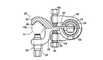
図1は、一端部がそれぞれ軸心に直角に切断された鉄筋12aおよび鉄筋12bを相互にガス圧接するために、一対の鉄筋12a、12bをそれらの軸心方向が一致し且つ端面が互いに突き合わされた状態で保持するガス圧接用鉄筋保持装置10を示している。このガス圧接用鉄筋保持装置10は、鉄筋12a、12bに互いに押圧する方向の加圧力を油圧を用いて発生させる単動型の油圧シリンダ(押圧シリンダ)16と、軸心方向の相対移動可能且つ軸心回りの相対回転可能に嵌合されることにより互いに同心である、大径管状部材である大径スリーブ22および小径管状部材である小径スリーブ24と、大径スリーブ22の一端部に設けられた第1鉄筋把持装置26と、小径スリーブ24に一体的に固設された第2鉄筋把持装置28とを備え、大径スリーブ22の端部に装着されて固定された油圧シリンダ16が小径スリーブ24を駆動し、軸心方向へ相対移動させるようになっている。
FIG. 1 shows that a pair of reinforcing
鉄筋12aおよび12bを把持状態で固定するための第1鉄筋把持装置26および第2鉄筋把持装置28は互いに同様に構成されているので、図1の側面を一部を切り欠いて示す図2および図3を用いて、小径スリーブ24に固定された第2鉄筋把持装置28を専ら説明する。第2鉄筋把持装置28は、小径スリーブ24の端部からその長手方向Lに直交する方向へ伸びるアーム部32と、そのアーム部32の先端においてC字状に分岐させられた一対の螺合部34、およびその螺合部34に対向した状態でその螺合部34に接続部35を介して一体的に接続された鉄筋受部36と、一方の螺合34に螺合された締付部材である締付ボルト38とを備えている。これら螺合部34および鉄筋受部36の間において、鉄筋12bは、その長手方向Lに直交する方向から押圧する締付ボルト38と、その締付ボルト38に対向するように鉄筋受部36に設けられた凹状或いはV字状の受面40との間で挟持されるようになっている。この受面40は、大径スリーブ22および小径スリーブ24の軸心Jに対して平行な面から構成されるとともにその軸心から等距離に形成されており、第1鉄筋把持装置26および第2鉄筋把持装置28に把持された鉄筋12aおよび12bは大径スリーブ22および小径スリーブ24の軸心Jと平行となり、且つ同心となるようにされている。
Since the first reinforcing
図2は、第2鉄筋把持装置28の構成を説明するために一部を切り欠いて示す図1の側面図であって、鉄筋12bを固定する位置まで締付ボルト38を前進させた状態を示している。図3は、図2と同様の側面図であるが、第2鉄筋把持装置28の螺合部34と接続部35を介してそれに接続された鉄筋受部36との間の開口Aから鉄筋12bを出し入れするに際して締付ボルト38がその螺合部34に当接する位置まで締付ボルト38を後進或いは後退させた状態を示している。
FIG. 2 is a side view of FIG. 1 with a part cut away for explaining the configuration of the second reinforcing
上記大径スリーブ22の端部には、軸心J方向に平行な長手状或いはスリット状の切欠き42が形成されるとともにその切欠き42を含むような切り欠きを有するC字状のリング部材44が固定されており、小径スリーブ24に固設された第2鉄筋把持装置28がその切欠き42を通して外部に突き出していると共に、所定の角度範囲で回動可能とされている。この第2鉄筋把持装置28の角度位置は、上記切り欠きを有するC字状のリング部材44の両端部に螺合されている一対の位置調節用ボルト46により鉄筋12a、12bを略同心に位置決めするように調整されるようになっている。
At the end of the large-
図4に示すように、締付ボルト38は、基端部において断面が正6角形に形成されたの頭部50と外周面に形成された雄ねじ52と、先端面に形成された嵌合穴54およびその開口縁に形成された環状摺接面56とを備えた円柱状のボルト本体58と、そのボルト本体58の嵌合穴54内に相対回転可能に嵌合された押圧部材60とを備えている。この押圧部材60は、押圧面62を鉄筋12a又は12b側に有する長方形板状の押圧板部64と、この押圧板部64のボルト本体58側の面65から突設され、その面65が環状摺接面56に摺接させられた状態で上記嵌合穴54内に嵌合される軸部66とを有している。この軸部66には、径方向に貫通し且つ複数個(本実施例では4個)のスチールボール68が収容された径方向穴70と、基端側端面に開口し且つその径方向穴70と交差するように軸心方向に形成された中心穴72とが形成される一方で、上記ボルト本体58には、その嵌合穴54の内周面に周方向に形成された環状溝74と、ニードル部材76が軸心方向に移動可能に収容された中心穴78とが形成されている。そして、その中心穴78の基端部に螺合され且つ相互にロックされた一対の埋込ボルト80とニードル部材76との間に設けられたスプリング82によってニードル部材76が付勢されると、そのニードル部材76の先端が径方向穴70内に収容されたスチールボール68を強制的に外周側へ移動させるので、そのスチールボール68が上記環状溝74内に係合させられる状態となり、押圧部材60とボルト本体58とがその軸心まわりの相対回転可能な状態で相互に離間不能に連結される。
As shown in FIG. 4, the
図1に戻って、大径スリーブ22は、油圧シリンダ16を装着するための第1装着装置84および第2装着装置86を一端部および他端部に螺着させることにより一体的にそれぞれ備えている。第1装着装置84および第2装着装置86は、大径スリーブ22よりも大径の短管状を成し、油圧シリンダ16の先端部に外径方向へ突設された係合突起16pを受け入れるために厚み方向に貫通したL字型の切欠き88をそれぞれ備えている。このL字型の切欠き88は、軸心Jに平行な方向に延びて端面に開口する軸方向部90と、その軸方向部90の端から周方向に延びる周方向部92とから構成されている。上記油圧シリンダ16の係合突起16pを軸方向部90内へ入れた状態で、その油圧シリンダ16の先端部を装着装置84または86の開口内に嵌め入れて押し込み、係合突起16pが軸方向部90の端へ到達した状態で油圧シリンダ16を軸心Jまわりに回転操作することにより係合突起16pを周方向部92内へ移動させることにより、油圧シリンダ16が着脱可能に装着されるようになっている。なお、小径スリーブ24の両端面には、上記油圧シリンダ16のピストンロッド16bの先端面を当接させるための当接部材94、96が固着されている。
Returning to FIG. 1, the
また、前記第1鉄筋把持装置26は、軸心Jまわりの相対回転可能且つ軸方向の移動不能に大径スリーブ22の一端部に設けられている。第1鉄筋把持装置26のアーム部32の基端には、大径スリーブ22の外径よりも僅かに大きい軸心J方向の貫通穴98を有する円筒状部100が形成されており、その円筒状部100内には大径スリーブ22の一端部が摺動可能に嵌め入れられることにより、図5の矢印Yに示すように、第1鉄筋把持装置26が大径スリーブ22に対して軸心Jまわりに相対回転可能とされている。また、大径スリーブ22の一端部において、短管状の装着装置84から上記円筒状部100の幅寸法と同じ距離だけ離隔した位置には、環状のストッパ102が溶接により固着されており、第1鉄筋把持装置26が大径スリーブ22に対して軸心J方向に相対移動不能とされている。なお、第1鉄筋把持装置26のアーム部32の基端に形成されている円筒状部100の外周面にはナット104が溶接されており、大径スリーブ22の外周面を押すことによって第1鉄筋把持装置26の大径スリーブ22に対する相対回転を止めるための回転止めボルト106がそのナット104に螺合されている。
The first
以上のように構成されたガス圧接用鉄筋保持装置10を用いて、垂直方向すなわち上方へ突き出す一方の鉄筋12aの端部に、かご状に組み付けられた鉄筋ユニット内で垂直方向に配列されている複数本の鉄筋のうちの一本である他方の鉄筋12bの端部をガス圧接する場合を、図6乃至図8を用いて説明する。
The gas pressure welding reinforcing bar holding device 10 configured as described above is arranged in the vertical direction within the reinforcing bar unit assembled in a basket shape at the end of one reinforcing
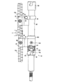
先ず、油圧シリンダ16が大径スリーブ22の一端部側(図の下端側)の第1装着装置84に装着され、且つ締付ボルト38、位置調節用ボルト46、および回転止めボルト106が緩められた圧接用鉄筋保持装置10が用意され、その圧接用鉄筋保持装置10の第1鉄筋把持装置26および第2鉄筋把持装置28が、上記一対の鉄筋12aおよび12bの端部を開口A内に受け入れた状態で締付ボルト38がそれぞれ締め付けられることによりそれらを把持した状態で固定され、位置調節用ボルト46が締め付けられる。これら一対の鉄筋12aおよび12bの把持位置は、一対の鉄筋12aおよび12bの端面から予め定められた一定の距離に定められている。図6は、この状態を示している。この状態における一対の鉄筋12aおよび12bは、軸心方向に離れておらず、かご状に組み付けられた鉄筋ユニット内で垂直方向に配列されている複数本の鉄筋の位置のばらつきによって、軸心方向の位置が図6のxに示す長さだけ重なっている。
First, the
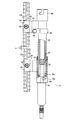
次に、油圧シリンダ16を駆動し、そのピストンロッド16bを突き出して小径スリーブ24およびそれに固定された第2鉄筋把持装置28を鉄筋12b側へ移動させ、一対の鉄筋12aおよび12bの端面の間に隙間yを形成させる。図7はこの状態を示している。この状態において、バール、レンチ等の棒状工具を鉄筋12bと大径スリーブ22との間に差し入れた状態で鉄筋12aと鉄筋12bとを同心とする方向へ操作することにより、一対の鉄筋12aと鉄筋12bとが芯出しされる。次いで、回転止めボルト106が締め付けられて大径スリーブ22と第1鉄筋把持装置26との相対回転が阻止されるとともに、必要に応じて位置調節用ボルト46の締め付け状態を変更してさらに芯出しされる。そして、上記油圧シリンダ16に対する油圧の供給を停止させてそのピストンロッド16bを引き込めることにより、上記一対の鉄筋12aおよび鉄筋12bの端面を相互に当接させる。
Next, the
次いで、油圧シリンダ16が第1装着装置84から取り外されて反対側の第2装着装置86に装着される。この状態で油圧シリンダ16を駆動することによりそのピストンロッド16bを突き出して小径スリーブ24およびそれに固定された第2鉄筋把持装置28を鉄筋12a側へ移動させ、一対の鉄筋12aおよび12bの端面間を所定の圧力で圧接させる。図8はこの状態を示す。この状態において、図示しない圧接バーナを用いて鉄筋12aおよび12bの端部が赤熱させられると、球状に膨出した状態となり、その圧接バーナによる加熱が停止させられると、一対の鉄筋12aおよび12bの接合が完了させられる。
Next, the
上述のように、本実施例のガス圧接用鉄筋保持装置10によれば、大径スリーブ22(大径管状部材)は、油圧シリンダ16を装着するための第1装着装置84および第2装着装置86を両端部にそれぞれ備え、第1鉄筋把持装置26は、軸心Jまわりの相対回転可能且つ軸方向の移動不能に大径スリーブ22の一端部に設けられていることから、一対の鉄筋12aおよび12bの端部の端面の軸心が一致しない場合でも、第1鉄筋把持装置26および第2鉄筋把持装置28は容易に一対の鉄筋12aおよび12bの端部を把持することができ、次いで第1鉄筋把持装置26を大径スリーブ22の一端部に対して相対回転させることによりその一対の鉄筋12aおよび12bの端部の軸心を一致させることができる。また、一対の鉄筋12aおよび12bの軸心方向位置が重なっていても、第1鉄筋把持装置26および第2鉄筋把持装置28は容易に一対の鉄筋の端部を把持することができ、次いで油圧シリンダ16を大径スリーブ22の一端部側に装着して小径管状スリーブ24を駆動することにより一対の鉄筋12aおよび12bの端部の重なりを容易に解消でき、そして第1鉄筋把持装置26を大径管状スリーブ22の一端部に対して相対回転させることによりその一対の鉄筋12aおよび12bの端部の軸心を能率よく一致させることができる。
As described above, according to the reinforcing bar holding device 10 for gas pressure welding of the present embodiment, the large diameter sleeve 22 (large diameter tubular member) has the first mounting
また、本実施例のガス圧接用鉄筋保持装置10によれば、第1鉄筋把持装置26と大径スリーブ22の相対回転を阻止するために操作される回転止めボルト106(相対回転阻止装置)が備えられているので、その回転止めボルト106を第1鉄筋把持装置26と大径スリーブ22との相対回転が許容する状態とすることにより、第1鉄筋把持装置26により把持された一方の鉄筋12aと第2鉄筋把持装置28により把持された他方の鉄筋12bとの芯出し作業が容易となるとともに、回転止めボルト106を第1鉄筋把持装置26と大径スリーブ22との相対回転を阻止する状態とすることにより、一方の鉄筋12aと他方の鉄筋12bとを圧接するときの芯ずれが好適に防止される利点がある。
Further, according to the gas pressure welding reinforcing bar holding device 10 of the present embodiment, the rotation stopping bolt 106 (relative rotation blocking device) operated to prevent relative rotation between the first reinforcing
また、本実施例のガス圧接用鉄筋保持装置10によれば、第2鉄筋把持装置28は小径管状スリーブ24(小径管状部材)の他端部に固定され、大径管状スリーブ22には、第2鉄筋把持装置28を厚み方向に貫通させ且つ軸心J方向へ案内するガイドスリット状の切欠き42が他端部に形成されていることから、第2鉄筋把持装置28は大径管状スリーブ22の一端部に設けられた第1鉄筋把持装置26に対して一定の距離を隔てて位置させられているので、一対の鉄筋12aおよび12bの端部を容易に把持することができる。また、大径管状スリーブ22には、第2鉄筋把持装置28を厚み方向に貫通させ且つ軸心J方向へ案内する切欠き42が他端部に形成されていることによって小径管状スリーブ24は大径管状スリーブ22に対して軸心方向の移動可能且つ軸回りの相対回転不能に嵌め入れられているので、一対の鉄筋12aおよび12bの端部を突き合わせた状態で圧接する過程での芯ずれが防止される。
Further, according to the gas pressure welding reinforcing bar holding device 10 of the present embodiment, the second reinforcing
また、本実施例のガス圧接用鉄筋保持装置10によれば、大径管状スリーブ22の軸心Jと第1鉄筋把持装置26および第2鉄筋把持装置28により把持された一対の鉄筋12aおよび12bの軸心とは互いに平行となるように設定されていることから、一対の鉄筋12aおよび12bの端部を突き合わせた状態で圧接する過程での芯ずれが防止される。
Further, according to the reinforcing bar holding device 10 for gas pressure welding of the present embodiment, the pair of reinforcing
また、本実施例のガス圧接用鉄筋保持装置10によれば、第1鉄筋把持装置26により把持された一方の鉄筋12aと第2鉄筋把持装置28により把持された他方の鉄筋12bとは、大径管状スリーブ22の一端部に装着された油圧シリンダ16が小径管状スリーブ24を軸心J方向へ駆動されることにより、軸心J方向において相互に離隔させられる利点がある。
Further, according to the reinforcing bar holding device 10 for gas pressure welding of the present embodiment, the one reinforcing
また、本実施例のガス圧接用鉄筋保持装置10によれば、第1鉄筋把持装置26により把持された一方の鉄筋12aと第2鉄筋把持装置28により把持された他方の鉄筋12bとは、大径管状スリーブ22の一端部に装着された油圧シリンダ16が小径管状スリーブ24を軸心J方向へ駆動されることにより相互に離隔させられた状態で、第1鉄筋把持装置26が大径管状スリーブ22に対して相対回転させられることにより、相互に芯出しが行われる利点がある。
Further, according to the reinforcing bar holding device 10 for gas pressure welding of the present embodiment, the one reinforcing
以上、本発明の一実施例を図面を参照して詳細に説明したが、本発明は更に他の態様でも実施される。 As mentioned above, although one Example of this invention was described in detail with reference to drawings, this invention is implemented also in another aspect.
例えば、前述の実施例において、大径スリーブ部材22の一端部および他端部に固設された第1装着装置84および第2装着装置86は、短円筒状部材とそれに形成されたL字型の切欠き88とから構成されており、油圧シリンダ16の先端部がそのL字型の切欠き88に係合させられることにより油圧シリンダ16装着されていたが、油圧シリンダ16を装着するための第1装着装置84および第2装着装置86は、油圧シリンダ16の先端部を螺合させる構造や、油圧シリンダ16の先端部をボルト締めにより装着させる構造等の他の装着構造を備えたものであってもよい。
For example, in the above-described embodiment, the first mounting
また、前述の実施例において、第1鉄筋把持装置26の基端部に設けられた円筒状部100内に大径スリーブ部材22が摺動可能に嵌め入れられることによって、第1鉄筋把持装置26が大径スリーブ部材22に相対回転可能に設けられていたが、円筒状部100が大径スリーブ部材22内に摺動可能に嵌め入れられる等の、他の構造であってもよい。
In the above-described embodiment, the large-
その他、一々例示はしないが、本発明はその主旨を逸脱しない範囲で種々変更を加え得るものである。 In addition, although not illustrated one by one, the present invention can be variously modified without departing from the gist thereof.
10:ガス圧接用鉄筋保持装置
12a:鉄筋、12b:鉄筋
16:油圧シリンダ(押圧シリンダ)
22:大径スリーブ(大径管状部材)
24:小径スリーブ(小径管状部材)
26:第1鉄筋把持装置
28:第2鉄筋把持装置
42:切欠き
84:第1装着装置
86:第2装着装置
106:回転止めボルト(相対回転阻止装置)
10: Rebar holding device for
22: Large diameter sleeve (large diameter tubular member)
24: Small diameter sleeve (small diameter tubular member)
26: first reinforcing bar gripping device 28: second reinforcing bar gripping device 42: notch 84: first mounting device 86: second mounting device 106: rotation stop bolt (relative rotation blocking device)
Claims (6)
前記大径管状部材は、前記押圧シリンダを装着するための装着装置を両端部にそれぞれ備え、
前記第1鉄筋把持装置は、軸心まわりの相対回転可能且つ軸方向の移動不能に前記大径管状部材の一端部に設けられている
ことを特徴とするガス圧接用鉄筋保持装置。 A large-diameter tubular member, a small-diameter tubular member fitted in the large-diameter tubular member so as to be relatively movable in the axial direction and not relatively rotatable around the axial center, and provided at one end of the large-diameter tubular member A first reinforcing bar gripping device for gripping one reinforcing bar, and a second reinforcing bar gripping device that is integrally fixed to the small-diameter tubular member and grips the other reinforcing bar. A pressing cylinder mounted on the other end of the large-diameter tubular member in a state in which the one reinforcing bar gripped and the other reinforcing bar gripped by the second reinforcing bar gripping device are in contact with each other pivots on the small-diameter tubular member Reinforcing bar holding device for gas pressure welding which fixes the one reinforcing bar and the other reinforcing bar to each other in the pressure contact state by driving in the direction of the gas,
The large-diameter tubular member includes a mounting device for mounting the pressing cylinder at both ends,
The first reinforcing bar gripping device is provided at one end of the large-diameter tubular member so as to be relatively rotatable about an axis and not movable in the axial direction.
ことを特徴とする請求項1のガス圧接用鉄筋保持装置。 The rebar holding device for gas pressure welding according to claim 1, further comprising a relative rotation prevention device operated to prevent relative rotation between the first rebar gripping device and the large-diameter tubular member.
前記大径管状部材には、該第2鉄筋把持装置を厚み方向に貫通させ且つ軸心方向へ案内するガイドスリットが他端部に形成されている
ことを特徴とする請求項1または2のガス圧接用鉄筋保持装置。 The second rebar gripping device is fixed to the other end of the small-diameter tubular member,
3. The gas according to claim 1, wherein the large-diameter tubular member is formed with a guide slit at the other end portion through which the second rebar gripping device penetrates in the thickness direction and guides in the axial direction. Rebar holding device for pressure welding.
Priority Applications (1)
| Application Number | Priority Date | Filing Date | Title |
|---|---|---|---|
| JP2008200145A JP4746652B2 (en) | 2008-08-01 | 2008-08-01 | Rebar holding device for gas pressure welding |
Applications Claiming Priority (1)
| Application Number | Priority Date | Filing Date | Title |
|---|---|---|---|
| JP2008200145A JP4746652B2 (en) | 2008-08-01 | 2008-08-01 | Rebar holding device for gas pressure welding |
Publications (2)
| Publication Number | Publication Date |
|---|---|
| JP2010037764A true JP2010037764A (en) | 2010-02-18 |
| JP4746652B2 JP4746652B2 (en) | 2011-08-10 |
Family
ID=42010596
Family Applications (1)
| Application Number | Title | Priority Date | Filing Date |
|---|---|---|---|
| JP2008200145A Active JP4746652B2 (en) | 2008-08-01 | 2008-08-01 | Rebar holding device for gas pressure welding |
Country Status (1)
| Country | Link |
|---|---|
| JP (1) | JP4746652B2 (en) |
Cited By (3)
| Publication number | Priority date | Publication date | Assignee | Title |
|---|---|---|---|---|
| JP2013130017A (en) * | 2011-12-21 | 2013-07-04 | Daia Co Ltd | Reinforcing-bar fixing device |
| CN114704100A (en) * | 2022-03-24 | 2022-07-05 | 中建八局第一建设有限公司 | High-strength pull rod tensioning tool and using method |
| CN117548887A (en) * | 2024-01-11 | 2024-02-13 | 潍坊昌大建设集团有限公司 | Steel bar welding positioning device |
Citations (2)
| Publication number | Priority date | Publication date | Assignee | Title |
|---|---|---|---|---|
| JPH02255294A (en) * | 1989-03-28 | 1990-10-16 | Kobe Steel Ltd | Position adjusting device for welding |
| JP3498046B2 (en) * | 2000-07-04 | 2004-02-16 | 株式会社ダイア | Rebar fixing device |
-
2008
- 2008-08-01 JP JP2008200145A patent/JP4746652B2/en active Active
Patent Citations (2)
| Publication number | Priority date | Publication date | Assignee | Title |
|---|---|---|---|---|
| JPH02255294A (en) * | 1989-03-28 | 1990-10-16 | Kobe Steel Ltd | Position adjusting device for welding |
| JP3498046B2 (en) * | 2000-07-04 | 2004-02-16 | 株式会社ダイア | Rebar fixing device |
Cited By (5)
| Publication number | Priority date | Publication date | Assignee | Title |
|---|---|---|---|---|
| JP2013130017A (en) * | 2011-12-21 | 2013-07-04 | Daia Co Ltd | Reinforcing-bar fixing device |
| CN114704100A (en) * | 2022-03-24 | 2022-07-05 | 中建八局第一建设有限公司 | High-strength pull rod tensioning tool and using method |
| CN114704100B (en) * | 2022-03-24 | 2023-06-20 | 中建八局第一建设有限公司 | High Jiang Lagan tensioning tool and use method thereof |
| CN117548887A (en) * | 2024-01-11 | 2024-02-13 | 潍坊昌大建设集团有限公司 | Steel bar welding positioning device |
| CN117548887B (en) * | 2024-01-11 | 2024-04-02 | 潍坊昌大建设集团有限公司 | Steel bar welding positioning device |
Also Published As
| Publication number | Publication date |
|---|---|
| JP4746652B2 (en) | 2011-08-10 |
Similar Documents
| Publication | Publication Date | Title |
|---|---|---|
| US9506250B2 (en) | Assembly for connecting rebar segments | |
| US9511488B2 (en) | King pin removal tool | |
| JP4746652B2 (en) | Rebar holding device for gas pressure welding | |
| JP2022508772A (en) | Hydraulic tension and release tool for inflatable fasteners | |
| JP2006226102A (en) | Connecting joint of steel pipe | |
| JP3146837U (en) | Rebar holding device for gas pressure welding | |
| CA2816439C (en) | Method and device for locking a support ring to a scaffolding column | |
| JP2000234333A (en) | Vertically connecting device for steel pipe sheet pile | |
| JP2016211302A (en) | Reinforcement holding device for gas pressure welding | |
| JP2826269B2 (en) | Column / beam joint structure using one side bolt | |
| US11137240B1 (en) | Pipe alignment tool | |
| JP4792506B2 (en) | Method and apparatus for rock drilling | |
| KR100996122B1 (en) | Mechanical connection method of members using automatic coupler connection apparatus and torque shear coupler | |
| JP2006289424A (en) | Welding equipment and tool in relation to joint core of steel pole | |
| JP5618601B2 (en) | Rebar holding device for gas pressure welding | |
| CN220592959U (en) | Joint fastening auxiliary device | |
| JP2001271421A (en) | Fixing part and bolt part used to join steel pipe column | |
| KR20140075833A (en) | Torque shear coupler for concentrated of shear stress | |
| JP6923143B2 (en) | Fittings for steel pipes | |
| JP3619170B2 (en) | Steel frame adjustment jig | |
| CN117248520B (en) | Auxiliary device for quick positioning of filling pile reinforcement cage | |
| JP7282641B2 (en) | Pressure welding jig for rebar | |
| KR101144138B1 (en) | Bidirectional auto-connecting apparatus and bidirectional auto-connecting method for member connecting using the same | |
| JP2008307588A (en) | Reinforcement fixing device | |
| JP2007098461A (en) | Welding equipment and tool in relation to joint core of steel pole |
Legal Events
| Date | Code | Title | Description |
|---|---|---|---|
| A977 | Report on retrieval |
Free format text: JAPANESE INTERMEDIATE CODE: A971007 Effective date: 20110214 |
|
| A131 | Notification of reasons for refusal |
Free format text: JAPANESE INTERMEDIATE CODE: A131 Effective date: 20110222 |
|
| A521 | Request for written amendment filed |
Free format text: JAPANESE INTERMEDIATE CODE: A523 Effective date: 20110329 |
|
| TRDD | Decision of grant or rejection written | ||
| A01 | Written decision to grant a patent or to grant a registration (utility model) |
Free format text: JAPANESE INTERMEDIATE CODE: A01 Effective date: 20110426 |
|
| A01 | Written decision to grant a patent or to grant a registration (utility model) |
Free format text: JAPANESE INTERMEDIATE CODE: A01 |
|
| A61 | First payment of annual fees (during grant procedure) |
Free format text: JAPANESE INTERMEDIATE CODE: A61 Effective date: 20110513 |
|
| FPAY | Renewal fee payment (event date is renewal date of database) |
Free format text: PAYMENT UNTIL: 20140520 Year of fee payment: 3 |
|
| R150 | Certificate of patent or registration of utility model |
Ref document number: 4746652 Country of ref document: JP Free format text: JAPANESE INTERMEDIATE CODE: R150 Free format text: JAPANESE INTERMEDIATE CODE: R150 |
|
| R250 | Receipt of annual fees |
Free format text: JAPANESE INTERMEDIATE CODE: R250 |
|
| R250 | Receipt of annual fees |
Free format text: JAPANESE INTERMEDIATE CODE: R250 |
|
| R250 | Receipt of annual fees |
Free format text: JAPANESE INTERMEDIATE CODE: R250 |
|
| R250 | Receipt of annual fees |
Free format text: JAPANESE INTERMEDIATE CODE: R250 |
|
| R250 | Receipt of annual fees |
Free format text: JAPANESE INTERMEDIATE CODE: R250 |
|
| R250 | Receipt of annual fees |
Free format text: JAPANESE INTERMEDIATE CODE: R250 |
|
| R250 | Receipt of annual fees |
Free format text: JAPANESE INTERMEDIATE CODE: R250 |
|
| R250 | Receipt of annual fees |
Free format text: JAPANESE INTERMEDIATE CODE: R250 |
|
| R250 | Receipt of annual fees |
Free format text: JAPANESE INTERMEDIATE CODE: R250 |
|
| R250 | Receipt of annual fees |
Free format text: JAPANESE INTERMEDIATE CODE: R250 |
|
| R250 | Receipt of annual fees |
Free format text: JAPANESE INTERMEDIATE CODE: R250 |