JP2010037726A - Structure for temporarily fixing pc girder of column capital section in cantilever erection method - Google Patents
Structure for temporarily fixing pc girder of column capital section in cantilever erection method Download PDFInfo
- Publication number
- JP2010037726A JP2010037726A JP2008198327A JP2008198327A JP2010037726A JP 2010037726 A JP2010037726 A JP 2010037726A JP 2008198327 A JP2008198327 A JP 2008198327A JP 2008198327 A JP2008198327 A JP 2008198327A JP 2010037726 A JP2010037726 A JP 2010037726A
- Authority
- JP
- Japan
- Prior art keywords
- girder
- column head
- temporary
- substructure
- concrete
- Prior art date
- Legal status (The legal status is an assumption and is not a legal conclusion. Google has not performed a legal analysis and makes no representation as to the accuracy of the status listed.)
- Granted
Links
- 239000004567 concrete Substances 0.000 claims abstract description 20
- 238000010276 construction Methods 0.000 claims abstract description 17
- 238000010008 shearing Methods 0.000 claims abstract description 7
- 229910000831 Steel Inorganic materials 0.000 claims description 25
- 239000010959 steel Substances 0.000 claims description 25
- 230000002093 peripheral effect Effects 0.000 claims description 7
- 239000000463 material Substances 0.000 claims description 5
- 239000011150 reinforced concrete Substances 0.000 description 3
- 230000003014 reinforcing effect Effects 0.000 description 2
- 210000002435 tendon Anatomy 0.000 description 2
- JEIPFZHSYJVQDO-UHFFFAOYSA-N iron(III) oxide Inorganic materials O=[Fe]O[Fe]=O JEIPFZHSYJVQDO-UHFFFAOYSA-N 0.000 description 1
- 238000005192 partition Methods 0.000 description 1
- 230000002265 prevention Effects 0.000 description 1
- 238000000638 solvent extraction Methods 0.000 description 1
- 239000000725 suspension Substances 0.000 description 1
Images

Landscapes
- Bridges Or Land Bridges (AREA)
Abstract
【課題】柱頭部PC桁仮固定部材の撤去が、短時間で、かつ容易に行なわれる柱頭部PC桁仮固定構造の提供。
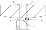
【解決手段】張り出し架設を行なう橋梁の柱頭部PC桁11を下部工10の上端との間にコンクリート製の仮沓12を介在させるとともに、下部工10に対しPC緊張材13を使用して仮固定する張り出し架設PC桁の柱頭部仮固定に際し、仮沓12は、上下面に一体に突設した多数のせん断キー24有し、該せん断キー24を仮沓上面側の柱頭部PC桁下面及び下部工上面に嵌合させ、該せん断キー24によって仮沓12と柱頭部PC桁11及び下部工10と間の水平方向のせん断力に対抗させる。
【選択図】図1Provided is a column head PC girder temporary fixing structure in which removal of a column head PC girder temporary fixing member is easily performed in a short time.
A concrete temporary bridge 12 is interposed between a bridge column head PC girder 11 and an upper end of a substructure 10 and a PC tension member 13 is temporarily used for the substructure 10. When temporarily fixing the column head of the overhanging construction PC girder to be fixed, the temporary anchor 12 has a number of shear keys 24 integrally projecting on the upper and lower surfaces, and the shear key 24 is provided on the lower surface of the column head PC girder on the upper surface side of the temporary anchor. It is fitted to the upper surface of the substructure, and the shear key 24 is used to counter the horizontal shearing force between the temporary tack 12 and the column head PC girder 11 and the substructure 10.
[Selection] Figure 1
Description
本発明は、橋桁を片持式に順次張り出すことによって構築する張り出し架設工法において、橋脚等の下部工上に設置する柱頭部PC桁を仮固定するための張り出し架設工法における柱頭部PC桁仮固定構造に関する。 The present invention relates to an overhanging construction method constructed by sequentially projecting bridge girders in a cantilevered manner, in which a column head PC girder temporary in an overhanging construction method for temporarily fixing a column head PC girder installed on a substructure such as a bridge pier is provided. It relates to a fixed structure.
一般に、PC橋の張り出し架設工法では、架設後の連続桁全体にプレストレスを導入させるものであるが、張り出し架設途中においては橋脚等の下部工と、該下部工上に支持させた柱頭部PC桁とを仮固定させておき、これによって架設時の安定性を確保している。 In general, in the overhanging construction method of PC bridge, prestress is introduced to the entire continuous girder after erection, but during the overhanging construction, a substructure such as a pier and a column head PC supported on the substructure. The girders are temporarily fixed to ensure the stability when erected.
また、互いに対向して順次張り出された桁の端部間が互いに付き合わされて連続桁が形成された後、連続桁全体にプレストレスを導入するために、前記仮固定を解除する必要がある。 Further, after the end portions of the beams that are sequentially projected to face each other are attached to each other to form a continuous beam, it is necessary to release the temporary fixing in order to introduce prestress to the entire continuous beam. .
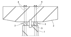
従来の仮固定構造は、図5に示す構造が一般的であった(例えば特許文献1)。同図において1は主として橋脚からなる下部工であり、2は柱頭部PC桁である。この柱頭部PC桁2を形成する際に、下部工1上に鉄筋コンクリート製の仮沓3を設置するとともに、下部工1内に下端側を定着させたPC緊張材4を、仮沓3に貫通させて柱頭部PC桁2に挿通し、その上端を柱頭部PC桁2の上面側に支持させて緊張定着させ、これによって張り出し桁の上下方向の回転モーメントに対抗させている。
The conventional temporary fixing structure is generally the structure shown in FIG. 5 (for example, Patent Document 1). In the figure, 1 is a substructure mainly composed of piers, and 2 is a column head PC girder. When forming the column
一方、これとは別に、H型鋼5の両端を下部工1と柱頭部PC桁2に埋設した状態で設置し、これによって地震時の水平方向のせん断力に対抗させている。
一般に、上述した連続桁式の張り出し架設工法では、片持式によって張り出し形成した対向する桁端部が接合された状態の連続桁全体にプレストレスを導入するものであり、桁端部間が接合された後、速やかにプレストレスを導入する必要があるが、柱頭部PC桁と下部工間が仮固定されたままではプレストレスが導入されにくい。このため仮固定を速やかに解除する必要がある。 In general, in the above-mentioned continuous girder type overhang construction method, prestress is introduced to the entire continuous girder in a state where opposing girder ends that are formed by cantilevering are joined, and the girder ends are joined. After this, it is necessary to quickly introduce prestress, but prestress is difficult to be introduced if the space between the column head PC girder and the substructure is temporarily fixed. For this reason, it is necessary to release the temporary fixing promptly.
しかし、上述した従来の柱頭部PC桁仮固定構造では、鉛直力を受けている仮沓は鉄筋コンクリート製である場合が多く、その撤去にはコンクリートのはつりと鉄筋の切断とを行なわなければならず、作業が著しく困難である。 However, in the conventional column head PC girder temporary fixing structure described above, the temporary anchor receiving the vertical force is often made of reinforced concrete, and the concrete must be suspended and the reinforcing bar cut to remove it. The work is extremely difficult.
また、水平方向のせん断抵抗を受け持っているH型鋼は、上下の端部が柱頭部PC桁及び下部工内に埋設されているため、これをガス等で切断しなければならず、切断後にはその切断面が露出することとなり、その露出面に防錆処理を施さなければならない。 In addition, the H-shaped steel that is responsible for the shear resistance in the horizontal direction has its upper and lower ends embedded in the column head PC girder and the substructure, so it must be cut with gas, etc. The cut surface will be exposed, and the exposed surface must be rust-proofed.
以上のように、従来の柱頭部PC桁仮固定の解除には多くの困難な作業が必要であるため、短時間での撤去は困難であるとともに、耐久性等の問題があった。 As described above, since the conventional column head PC girder temporary fixing requires many difficult operations, removal in a short time is difficult and there are problems such as durability.
本発明はこのような従来の問題に鑑み、柱頭部PC桁仮固定部材の撤去が、短時間で、かつ容易に行なわれ、桁連続後に短時間でプレストレス導入作業を行なうことができる張り出し架設工法における柱頭部PC桁仮固定構造の提供を目的としてなされたものである。 In view of such a conventional problem, the present invention provides an overhanging structure in which the column head PC girder temporary fixing member can be easily removed in a short time and the prestress can be introduced in a short time after the girder is continued. The purpose is to provide a column head PC girder temporary fixing structure in the construction method.
上述の如き従来の問題を解決し、所期の目的を達成するための請求項1に記載の発明の特徴は、張り出し架設を行なう橋梁の柱頭部PC桁を下部工の上端との間に、コンクリート製の仮沓を介在させるとともに、該柱頭部PC桁を下部工に対しPC緊張材を使用して仮固定する張り出し架設PC桁の柱頭部仮固定構造において、
前記仮沓は、上下面に一体に突設した多数のせん断キーを有し、該せん断キーを仮沓上面側の柱頭部PC桁下面及び下部工上面に嵌合させ、該せん断キーによって仮沓と柱頭部PC桁及び下部工と間の水平方向のせん断力に対抗させるようにしたことにある。
The feature of the invention according to claim 1 for solving the conventional problems as described above and achieving the intended purpose is that the bridge column head PC girder for overhanging construction is placed between the upper end of the substructure. In the column head temporary fixing structure of the overhanging construction PC girder in which a concrete temporary fence is interposed and the column head PC girder is temporarily fixed to the substructure using a PC tension material,
The temporary tack has a plurality of shear keys integrally projecting on the upper and lower surfaces, and the shear keys are fitted to the lower surface of the column head PC girder and the lower construction surface on the upper face of the temporary tack, This is to counter the horizontal shearing force between the column head PC girder and the substructure.
請求項2に記載の発明の特徴は、請求項1の構成に加え、前記仮沓は、側部周面を構成する鋼殻を有し、該鋼殻内に無筋コンクリートを充填して構成されていることにある。 According to a second aspect of the present invention, in addition to the structure of the first aspect, the temporary tack has a steel shell constituting a side peripheral surface, and the steel shell is filled with unreinforced concrete. There is in being.
請求項3に記載の発明の特徴は、請求項1又は2の何れか1の請求項の構成に加え、前記せん断キーは、橋軸方向と直交する向きの凹凸条を橋軸方向に交互に配置した波型に形成することによって構成されていることにある。 According to a third aspect of the present invention, in addition to the configuration of the first or second aspect of the invention, the shear key is configured so that the ridges in the direction orthogonal to the bridge axis direction are alternately arranged in the bridge axis direction. That is, it is configured by forming the wave shape to be arranged.
本発明においては、仮沓として、上下面に一体に突設した多数のせん断キー有するものを使用し、該せん断キーを仮沓上面側の柱頭部PC桁下面及び下部工上面に嵌合させ、該せん断キーによって仮沓と柱頭部PC桁及び下部工と間の水平方向のせん断力に対抗させるようにしたことにより、従来使用していた水平方向のせん断抵抗を受け持たせるH型鋼が不要になり、柱頭部PC桁の仮固定解除作業は、PC緊張材の緊張解除と、仮沓の除去作業によって完了するため、従来に比べて作業工数が少なく、短時間で連続桁のプレストレスの導入を完了することができる。 In the present invention, as a temporary tack, use a thing having a large number of shear keys integrally projecting on the upper and lower surfaces, the shear key is fitted to the bottom face of the column head PC girder on the upper face side of the temporary tack and the lower work surface, By using the shear key to oppose the horizontal shearing force between the anchor and the column head PC girder and the substructure, there is no need for the H-shaped steel that provides the horizontal shearing resistance that has been used in the past. Therefore, the temporary fixation release work for the column head PC girders is completed by releasing the tension of the PC tendon and removing the temporary tacks. Can be completed.
また、水平方向のせん断抵抗を受け持たせるH型鋼を使用しないため、その切断作業や切断作業後の防錆作業が不要となり、作業工数が著しく削減される。 Further, since the H-shaped steel that imparts horizontal shear resistance is not used, the cutting work and the rust prevention work after the cutting work are not required, and the number of work steps is significantly reduced.
また、本発明では、前記仮沓は、側部周面を構成する鋼殻を有し、該鋼殻内に無筋コンクリートを充填して構成されていることにより、仮沓の撤去に際し、鋼殻はガス切断等によって切断することにより容易に除去でき、また、鋼殻除去後に残るコンクリートは無筋であるため、コンクリートブレーカーによって容易かつ短時間に除去できる。 Further, in the present invention, the temporary tack has a steel shell constituting the side peripheral surface, and is constituted by filling the steel shell with unreinforced concrete, so that the temporary tack is removed when the steel is removed. The shell can be easily removed by cutting by gas cutting or the like, and the concrete remaining after the removal of the steel shell is straight, so it can be removed easily and in a short time by a concrete breaker.
更に、本発明では、前記せん断キーは、橋軸方向と直交する向きの凹凸条を橋軸方向に交互に配置した波型に形成することによって構成されていることにより、マッチキャスト形式によって仮沓の上下面のせん断キーと整合する形状に、下側の下部工及び上側の柱頭部PC桁の各対応面が容易に形成することができる。 Furthermore, in the present invention, the shear key is formed by forming a corrugated shape in which the ridges in the direction perpendicular to the bridge axis direction are alternately arranged in the bridge axis direction, so that the match key type is used as the temporary key. The corresponding surfaces of the lower substructure and the upper column head PC girder can be easily formed in a shape that matches the upper and lower shear keys.
次に本発明の実施の形態を図1〜図4に示した実施例に基づいて説明する。図において符号10は、橋脚等の下部工であり、11は下部工10上に仮固定した柱頭部PC桁である。この仮固定は、仮沓12とPC緊張材13とによってなされている。PC緊張材13は下端が下部工10内に埋設されて定着され、上端側が仮沓12を通して柱頭部PC桁11に貫通され、その上端が支圧板を介して定着具14により緊張定着されている。
Next, embodiments of the present invention will be described based on the examples shown in FIGS. In the figure,
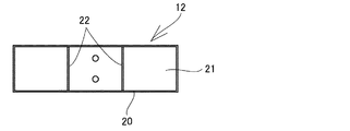
仮沓12は、図2〜図4に示すように、上下面を除く側部周面に鋼鈑からなる鋼殻20を備え、その内部にコンクリート21を打設して構成されており、コンクリートは鉄筋を使用しない無筋コンクリート構造となっている。
As shown in FIGS. 2 to 4, the
鋼殻20は、仮沓12の側部周面を構成している他、その内部を複数の隔室に仕切る隔壁22が一体に備えられ、その各隔室内にコンクリート21が充填されて構成されている。
The
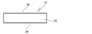
仮沓12の上下面は、前記鋼殻20の上下縁部より後述するせん断キーの高さ分だけ突出されてコンクリート21が打設されており、該上下面に多数のせん断キー24が一体に形成されている。
The upper and lower surfaces of the
仮沓12の上下面は、凹溝24aと突条24bが交互に並べて形成されることにより断面が波型に形成され、その波型の凸部がせん断キー24となっている。この突条24aからなるせん断キー24を柱頭部PC桁11の橋軸方向と直交する方向に向けて設置している。
The upper and lower surfaces of the
この仮沓12の上下面と接合する柱頭部PC桁11の下面及び下部工10の上面は、互いに嵌りあう形状に形成されており、仮沓のせん断キー24の間に柱頭部PC桁11下面及び下部工上面のせん断キー25が密に嵌り合っている構造となっている。
The lower surface of the column
仮沓12の設置は、先ず仮沓12を鋼殻20付きのコンクリートブロックとして形成しておき、これを下部工の上面形成に際し、仮沓20を下部工コンクリートの固化前に該下部工上面に置くことによって、仮沓20の下面が互いに密着して嵌りあう形状にせん断キー25を形成し、このようにして下部工10の上面に設置した仮沓20の上面に直接柱頭部PC桁11を形成するコンクリートを打設することによって仮沓20の上面が互いに密着して嵌りあう形状にせん断キー25を形成することができる。
First, the
尚、上述したせん断キー24,25は、この実施例では断面波型に形成しているが、この他、断面が台形等の角型突条であってもよく、更には、格子状の凹溝を形成することによって形成される角型の突起であってもよい。
The
このように、上下面にせん断キーを有する仮沓20を使用し、その上下面のせん断キー24を柱頭部PC桁11下面及び下部工10上面に密に嵌め合わせるとともに、PC緊張材13によって下部工10と柱頭部PC桁11間を引き寄せる方向の荷重をかけることにより、せん断キー24の存在によって、橋桁の張り出し施工時に生じる水平方向のせん断力に十分に対抗させることができ、従来使用していた耐せん断力用のH型鋼が不要となる。
In this way, the
また、仮固定時及び橋桁張り出し施工時に仮沓12に作用する垂直荷重に対しては外周面の鋼殻20によって座屈が防止され、鉄筋コンクリートと同様又はそれ以上に、耐えることができる。
Further, buckling is prevented by the
そして、仮固定を解除する際には、従来と同様にPC緊張材13による緊張を解除した後、仮沓12の周面の鋼殻20は、その表面から切断することによって容易に除去でき、鋼殻20を除去したあとに残るコンクリート21は、鉄筋が埋設されていない無筋コンクリートであるため、コンクリートブレーカー等の簡易な装置により容易に除去することができる。
And, when releasing the temporary fixation, after releasing the tension by the
このように、下部工間に跨った連続桁が完成した後の仮固定の解除は、PC緊張材13による緊張解除と、前述した仮沓12の短時間での容易な除去作業によってなされ、従来のようなH型鋼の除去が不要であるため、連続桁に対するプレストレスの導入作業を早期に行なうことができる。
As described above, the temporary fixation after the continuous girder between the substructures is completed is released by the tension release by the
10 下部工
11 柱頭部PC桁
12 仮沓
13 PC緊張材
14 定着具
20 鋼殻
21 コンクリート
22 隔壁
24 せん断キー
24a 凹溝
24b 突条
25 せん断キー
DESCRIPTION OF
Claims (3)
前記仮沓は、上下面に一体に突設した多数のせん断キーを有し、該せん断キーを仮沓上面側の柱頭部PC桁下面及び下部工上面に嵌合させ、該せん断キーによって仮沓と柱頭部PC桁及び下部工と間の水平方向のせん断力に対抗させるようにしたことを特徴としてなる張り出し架設PC桁の柱頭部仮固定構造。 A concrete temporary fence is interposed between the column head PC girder of the bridge for overhanging construction and the upper end of the substructure, and the column head PC girder is temporarily fixed to the substructure using a PC tension material. In the column head temporary fixing structure of overhanging construction PC girder,
The temporary tack has a plurality of shear keys integrally projecting on the upper and lower surfaces, and the shear keys are fitted to the lower surface of the column head PC girder and the lower construction surface on the upper face of the temporary tack, Column head temporary fixing structure of overhanging PC girder characterized in that it is made to resist horizontal shearing force between the column head PC girder and substructure.
Priority Applications (1)
| Application Number | Priority Date | Filing Date | Title |
|---|---|---|---|
| JP2008198327A JP5131590B2 (en) | 2008-07-31 | 2008-07-31 | Column head PC girder temporary fixing structure in overhang construction method |
Applications Claiming Priority (1)
| Application Number | Priority Date | Filing Date | Title |
|---|---|---|---|
| JP2008198327A JP5131590B2 (en) | 2008-07-31 | 2008-07-31 | Column head PC girder temporary fixing structure in overhang construction method |
Publications (2)
| Publication Number | Publication Date |
|---|---|
| JP2010037726A true JP2010037726A (en) | 2010-02-18 |
| JP5131590B2 JP5131590B2 (en) | 2013-01-30 |
Family
ID=42010558
Family Applications (1)
| Application Number | Title | Priority Date | Filing Date |
|---|---|---|---|
| JP2008198327A Active JP5131590B2 (en) | 2008-07-31 | 2008-07-31 | Column head PC girder temporary fixing structure in overhang construction method |
Country Status (1)
| Country | Link |
|---|---|
| JP (1) | JP5131590B2 (en) |
Cited By (10)
| Publication number | Priority date | Publication date | Assignee | Title |
|---|---|---|---|---|
| CN102493364A (en) * | 2011-12-23 | 2012-06-13 | 中铁大桥局股份有限公司 | Ballasting method in large-span girder cantilever construction |
| CN102518046A (en) * | 2011-12-29 | 2012-06-27 | 广东冠粤路桥有限公司 | Method for eliminating secondary internal force of sinking of support saddle of continuous beam during cantilever construction |
| CN103132463A (en) * | 2013-03-12 | 2013-06-05 | 中国建筑第六工程局有限公司 | Movable hanger operating platform and manufacturing, installing, using and removing methods thereof |
| CN103410102A (en) * | 2013-08-29 | 2013-11-27 | 浙江省宏途交通建设有限公司 | H-shaped double column pier wide-bridge-surface cantilever temporary consolidation structure and construction method thereof |
| KR101395129B1 (en) | 2013-11-25 | 2014-05-15 | (주) 효성 | Precast panel and slab construction method using the same |
| CN111305080A (en) * | 2020-03-31 | 2020-06-19 | 南京林业大学 | Temporary consolidation bearing for cantilever construction of continuous girder bridge |
| CN112030780A (en) * | 2020-08-19 | 2020-12-04 | 中铁大桥局第七工程有限公司 | Steel arch bridge cantilever erection method |
| CN112695637A (en) * | 2020-12-24 | 2021-04-23 | 云南交投公路建设第二工程有限公司 | Tower beam temporary consolidation supporting structure easy to unload quickly and manufacturing and construction process |
| CN115059024A (en) * | 2022-07-09 | 2022-09-16 | 水利部交通运输部国家能源局南京水利科学研究院 | Simple-supported box-type water transmission and transfer combined structure and construction method using interlocking connection |
| CN116065476A (en) * | 2023-02-15 | 2023-05-05 | 中国建筑第五工程局有限公司 | A template-free ultra-large-scale UHPC-CSW-NC composite cover beam and its construction method |
Families Citing this family (2)
| Publication number | Priority date | Publication date | Assignee | Title |
|---|---|---|---|---|
| WO2014025570A1 (en) | 2012-08-08 | 2014-02-13 | 3M Innovative Properties Company | Barrier film constructions and methods of making same |
| TWI610806B (en) | 2012-08-08 | 2018-01-11 | 3M新設資產公司 | Barrier film, method of manufacturing the barrier film, and object including the barrier film |
Citations (2)
| Publication number | Priority date | Publication date | Assignee | Title |
|---|---|---|---|---|
| JPH09256325A (en) * | 1996-03-22 | 1997-09-30 | Kawata Kensetsu Kk | Temporary abutment for pier |
| JP2002242207A (en) * | 2001-02-22 | 2002-08-28 | Taisei Corp | Structural foundation support structure |
-
2008
- 2008-07-31 JP JP2008198327A patent/JP5131590B2/en active Active
Patent Citations (2)
| Publication number | Priority date | Publication date | Assignee | Title |
|---|---|---|---|---|
| JPH09256325A (en) * | 1996-03-22 | 1997-09-30 | Kawata Kensetsu Kk | Temporary abutment for pier |
| JP2002242207A (en) * | 2001-02-22 | 2002-08-28 | Taisei Corp | Structural foundation support structure |
Cited By (14)
| Publication number | Priority date | Publication date | Assignee | Title |
|---|---|---|---|---|
| CN102493364A (en) * | 2011-12-23 | 2012-06-13 | 中铁大桥局股份有限公司 | Ballasting method in large-span girder cantilever construction |
| CN102493364B (en) * | 2011-12-23 | 2014-01-15 | 中铁大桥局股份有限公司 | Ballasting method in large-span girder cantilever construction |
| CN102518046B (en) * | 2011-12-29 | 2014-05-21 | 广东冠粤路桥有限公司 | Method for eliminating secondary internal force of sinking of support saddle of continuous beam during cantilever construction |
| CN102518046A (en) * | 2011-12-29 | 2012-06-27 | 广东冠粤路桥有限公司 | Method for eliminating secondary internal force of sinking of support saddle of continuous beam during cantilever construction |
| CN103132463A (en) * | 2013-03-12 | 2013-06-05 | 中国建筑第六工程局有限公司 | Movable hanger operating platform and manufacturing, installing, using and removing methods thereof |
| CN103132463B (en) * | 2013-03-12 | 2015-06-24 | 中国建筑第六工程局有限公司 | Movable hanger operating platform and manufacturing, installing, using and removing methods thereof |
| CN103410102A (en) * | 2013-08-29 | 2013-11-27 | 浙江省宏途交通建设有限公司 | H-shaped double column pier wide-bridge-surface cantilever temporary consolidation structure and construction method thereof |
| KR101395129B1 (en) | 2013-11-25 | 2014-05-15 | (주) 효성 | Precast panel and slab construction method using the same |
| CN111305080A (en) * | 2020-03-31 | 2020-06-19 | 南京林业大学 | Temporary consolidation bearing for cantilever construction of continuous girder bridge |
| CN112030780A (en) * | 2020-08-19 | 2020-12-04 | 中铁大桥局第七工程有限公司 | Steel arch bridge cantilever erection method |
| CN112695637A (en) * | 2020-12-24 | 2021-04-23 | 云南交投公路建设第二工程有限公司 | Tower beam temporary consolidation supporting structure easy to unload quickly and manufacturing and construction process |
| CN112695637B (en) * | 2020-12-24 | 2022-11-29 | 云南交投公路建设第二工程有限公司 | Tower beam temporary consolidation supporting structure easy to unload quickly and manufacturing and construction process |
| CN115059024A (en) * | 2022-07-09 | 2022-09-16 | 水利部交通运输部国家能源局南京水利科学研究院 | Simple-supported box-type water transmission and transfer combined structure and construction method using interlocking connection |
| CN116065476A (en) * | 2023-02-15 | 2023-05-05 | 中国建筑第五工程局有限公司 | A template-free ultra-large-scale UHPC-CSW-NC composite cover beam and its construction method |
Also Published As
| Publication number | Publication date |
|---|---|
| JP5131590B2 (en) | 2013-01-30 |
Similar Documents
| Publication | Publication Date | Title |
|---|---|---|
| JP5131590B2 (en) | Column head PC girder temporary fixing structure in overhang construction method | |
| CA2069814C (en) | Load supporting structure | |
| JP6375079B1 (en) | Joint structure of precast composite floor slab perpendicular to the bridge axis and its construction method | |
| WO2006038620A1 (en) | Joined part structure of pedestal and method of joining pedestal | |
| JP2007023714A (en) | Synthetic floor slab using synthetic steel, composite floor slab bridge or composite girder bridge, and construction method thereof | |
| JP2008063803A (en) | Synthetic floor slabs, synthetic floor slab bridges, or composite girder bridges with inner ribbed shaped steel | |
| JP5372587B2 (en) | Steel / concrete composite floor slab | |
| JP2009133114A (en) | Reinforcement structure for wall column members | |
| JP2006112179A (en) | Bridge girder construction method | |
| US11105111B2 (en) | Buttress assembly for seismic reinforcing of building having non-bearing walls | |
| KR100728106B1 (en) | Cantilevered part installation structure and construction method of bridge deck | |
| JP2005061081A (en) | Precast slab joining structure and precast slab joining method | |
| JP5029271B2 (en) | Structure of a continuous I-girder bridge and its I-girder near its intermediate support | |
| JP2007270600A (en) | Prestress introducing method to filling part between precast concrete members | |
| JP2006169837A (en) | Reinforced concrete column beam connection structure | |
| JP2001172916A (en) | Corrugated synthetic floor slab | |
| JP2011247045A (en) | Reinforcement method for bridge abutment | |
| JP4492422B2 (en) | Structure near the intermediate support of a continuous I-girder bridge | |
| JP3851162B2 (en) | Stopper for bridge | |
| JP2008063805A (en) | Connection structure of full precast concrete slab | |
| JP6684088B2 (en) | Seismic retrofitting structure and method for existing buildings | |
| JP3047817B2 (en) | Method of placing concrete so that it can be separated | |
| JP2015086562A (en) | Abutment reinforcing structure | |
| JP2004332486A (en) | Pillar structure | |
| JP4193708B2 (en) | Steel concrete composite floor |
Legal Events
| Date | Code | Title | Description |
|---|---|---|---|
| A621 | Written request for application examination |
Free format text: JAPANESE INTERMEDIATE CODE: A621 Effective date: 20110425 |
|
| A977 | Report on retrieval |
Free format text: JAPANESE INTERMEDIATE CODE: A971007 Effective date: 20120612 |
|
| TRDD | Decision of grant or rejection written | ||
| A01 | Written decision to grant a patent or to grant a registration (utility model) |
Free format text: JAPANESE INTERMEDIATE CODE: A01 Effective date: 20121003 |
|
| A01 | Written decision to grant a patent or to grant a registration (utility model) |
Free format text: JAPANESE INTERMEDIATE CODE: A01 |
|
| A61 | First payment of annual fees (during grant procedure) |
Free format text: JAPANESE INTERMEDIATE CODE: A61 Effective date: 20121025 |
|
| FPAY | Renewal fee payment (event date is renewal date of database) |
Free format text: PAYMENT UNTIL: 20151116 Year of fee payment: 3 |
|
| R150 | Certificate of patent or registration of utility model |
Ref document number: 5131590 Country of ref document: JP Free format text: JAPANESE INTERMEDIATE CODE: R150 |
|
| R250 | Receipt of annual fees |
Free format text: JAPANESE INTERMEDIATE CODE: R250 |
|
| R250 | Receipt of annual fees |
Free format text: JAPANESE INTERMEDIATE CODE: R250 |
|
| R250 | Receipt of annual fees |
Free format text: JAPANESE INTERMEDIATE CODE: R250 |
|
| S531 | Written request for registration of change of domicile |
Free format text: JAPANESE INTERMEDIATE CODE: R313531 |
|
| R350 | Written notification of registration of transfer |
Free format text: JAPANESE INTERMEDIATE CODE: R350 |
|
| S533 | Written request for registration of change of name |
Free format text: JAPANESE INTERMEDIATE CODE: R313533 |
|
| R350 | Written notification of registration of transfer |
Free format text: JAPANESE INTERMEDIATE CODE: R350 |
|
| R250 | Receipt of annual fees |
Free format text: JAPANESE INTERMEDIATE CODE: R250 |