JP2010037715A - Horizontal member - Google Patents
Horizontal member Download PDFInfo
- Publication number
- JP2010037715A JP2010037715A JP2008197893A JP2008197893A JP2010037715A JP 2010037715 A JP2010037715 A JP 2010037715A JP 2008197893 A JP2008197893 A JP 2008197893A JP 2008197893 A JP2008197893 A JP 2008197893A JP 2010037715 A JP2010037715 A JP 2010037715A
- Authority
- JP
- Japan
- Prior art keywords
- horizontal member
- option
- attached
- wall
- panel
- Prior art date
- Legal status (The legal status is an assumption and is not a legal conclusion. Google has not performed a legal analysis and makes no representation as to the accuracy of the status listed.)
- Granted
Links
Images


Abstract
Description
本発明は、支柱の上端部間に支持される横架材に関するものである。 The present invention relates to a horizontal member supported between upper end portions of support columns.
近時、オフィス等において所定の作業空間を他の空間と仕切り得るように、その作業空間を、複数の支柱とそれら支柱の上端部間に亘って設けられる横架材とを備えたフレーム構造体によって形成する態様が知られている。 Recently, a frame structure including a plurality of support columns and a horizontal member provided between upper ends of the support columns so that a predetermined work space can be partitioned from other spaces in an office or the like. A mode of forming by is known.
横架材は、下方に開口する開口部を幅方向に沿って連続して有する取付部を備えたものであり、この取付部に、パネル等のオプション部材を取付可能に構成している(例えば特許文献1参照)。
しかしながら、上述した態様は、パネルや照明装置等のオプション部材を取り付ける対象が、横架材における単一の取付部のみであるため、多種類のオプション部材を横架材に付帯させたい場合、それら全種類のオプション部材が共通の取付部に取付可能な構造を有するものでなければならず、逆に、横架材側からみれば、単一の取付部を全種類のオプション部材が取付可能な構造にしなければならず、横架材及び各種オプション部材の双方にとって設計自由度が制約されるという不具合があった。 However, in the above-described aspect, the option member such as a panel or a lighting device is attached only to a single attachment portion in the horizontal member. Therefore, when various kinds of optional members are attached to the horizontal member, All types of optional members must have a structure that can be attached to a common mounting part. Conversely, when viewed from the horizontal member side, a single mounting part can be attached to all types of optional members. There is a problem that the design freedom is restricted for both the horizontal member and various optional members.
本発明は、このような課題に着目してなされたものであって、主たる目的は、取付部に対する取付構造が異なる複数種類のオプション部材を好適に取り付けることが可能な横架材を提供することにある。 The present invention has been made paying attention to such problems, and a main object thereof is to provide a horizontal member capable of suitably attaching a plurality of types of optional members having different attachment structures to the attachment portion. It is in.
すなわち、本発明の横架材は、隣接する支柱の上端部間に配され、且つ複数種類のオプション部材が取付可能なものであって、前記複数種類のオプション部材のうち一又は複数のオプション部材を取り付けるための第1取付部と、当該第1取付部に対して上下方向に離間し、且つ前記複数種類のオプション部材のうち前記第1取付部に取付可能なオプション部材とは異なる他のオプション部材を取り付けるための第2取付部とを備えてなり、取り付けるオプション部材に応じて、前記第1取付部を下端部側に位置付けた第1姿勢と、前記第2取付部を下端部側に位置付けた第2姿勢との間で上下反転可能なものであることを特徴とする。 That is, the horizontal member of the present invention is arranged between the upper end portions of adjacent struts and can be attached with a plurality of types of option members, and one or a plurality of option members among the plurality of types of option members A first attachment portion for attaching the first attachment portion, and an option that is spaced apart from the first attachment portion in the vertical direction and is different from the option member that can be attached to the first attachment portion among the plurality of types of option members And a second posture for positioning the first mounting portion on the lower end side, and the second mounting portion on the lower end side according to an optional member to be mounted. Further, it is characterized in that it can be turned upside down between the second posture.
このようなものであれば、第1取付部に取付可能なオプション部材を横架材に取り付ける場合には、横架材を第1姿勢の状態で支柱の上端部間に配置すればよく、一方、第2取付部に取付可能なオプション部材を横架材を取り付ける場合には、横架材を上下反転させて第2姿勢の状態で支柱の上端部間に配置すればよいため、横架材に取り付けるオプション部材の種類が多種に亘る場合であっても、全てのオプション部材が同一の取付対象部(単一の取付部)にのみ取付可能なものでなければならないという制約が生じず、取付構造が異なる複種類のオプション部材を、横架材を上下反転させることにより好適に取り付けることができる。そして、このことは、横架材にとって、全種類のオプション部材が取付可能な取付部にしなければならないという制約がなくなり、例えば、多種類のオプション部材を、各オプション部材に要求される機能や用途等に応じて2グループに分類し、第1取付部を一方のグループに属するオプション部材の取付に適した構造とするとともに、第2取付部を他方のグループに属するオプション部材の適した構造とすることが可能となり、各種オプション部材の良好な取付状態の実現に多いに寄与する。 If it is such, when attaching the optional member which can be attached to the 1st attachment part to a horizontal member, what is necessary is just to arrange | position a horizontal member between the upper end parts of a support | pillar in the state of a 1st attitude | position. When installing a horizontal member as an optional member that can be attached to the second attachment part, the horizontal member may be placed between the upper ends of the columns in the second posture by turning the horizontal member upside down. Even when there are a wide variety of optional parts to be attached to the unit, there is no restriction that all the optional parts must be attachable only to the same attachment target part (single attachment part). Multiple types of optional members having different structures can be suitably attached by turning the horizontal member upside down. And this eliminates the restriction that the horizontal member has to be an attachment part to which all types of option members can be attached. For example, various types of option members can be used for functions and applications required for each option member. The first mounting portion is structured to be suitable for mounting an optional member belonging to one group, and the second mounting portion is structured to be suitable for an optional member belonging to the other group. This contributes to the realization of a good mounting state of various optional members.
特に、前記第1取付部が、厚み方向に対向する一対の第1対向壁と、これら各第1対向壁の内向面に設けられオプション部材の一部が係わり合う係わり合い部とを備えたものであり、前記第2取付部が、厚み方向に対向する一対の第2対向壁と、これら各第2対向壁間に形成されオプション部材の一部又は全部が収容可能な収容部とを備えたものであれば、これら係わり合い部及び収容部を利用して各オプション部材の良好な取付状態を確保することができるとともに、オプション部材の取付に積極的に寄与するこれら係わり合い部及び収容部がそれぞれ対をなす第1対向壁、第2対向壁によって外部から視認できない又は視認し難いため、看者に煩雑な印象を与えないシンプルな外観を呈するものとなる。 In particular, the first mounting portion includes a pair of first opposing walls opposed to each other in the thickness direction, and an engaging portion provided on an inward surface of each of the first opposing walls with which a part of the option member is engaged. The second mounting portion includes a pair of second opposing walls opposed to each other in the thickness direction, and an accommodating portion that is formed between the second opposing walls and that can accommodate part or all of the optional member. If it is a thing, while being able to ensure the favorable attachment state of each option member using these engagement parts and storage parts, these engagement parts and storage parts which contribute to attachment of an option member positively Since the first opposing wall and the second opposing wall that make a pair cannot be visually recognized or difficult to visually recognize from the outside, a simple appearance that does not give a complicated impression to the viewer is exhibited.
さらに、オプション部材の中には、取付部に取り付けた状態で横架材の幅方向に沿ってスライド移動可能なものであることが要求されるものもあれば、このようなスライド移動が要求されないものもあり、従来のように例えば単一の取付部に案内レールを設け、この案合レールに沿ってオプション部材のスライド移動を案内させる態様とした場合、スライド移動が要求されないオプション部材をこの取付部に取り付ける場合には案内レールがかえって邪魔になる或いは過剰スペックに陥るという不具合が生じる。一方、本発明の横架材は、前記係わり合い部が、前記オプション部材をスライド移動可能に支持するスライド移動案内部としても機能するものであるため、スライド移動が要求されるオプション部材は第1取付部に取り付けることによって、その機能を発揮し得るものとなる上に、別途専用のスライド移動案内部を設ける必要がなく、構造の簡略化及びコストの削減に資する。また、スライド移動が要求されないオプション部材は第2取付部の収容部を利用して横架材に取り付ければよく、この際、スライド移動案内部がスライド移動が要求されないオプション部材の取り付けに支障を来たすことがない。 Furthermore, some optional members are required to be slidable along the width direction of the horizontal member in a state of being attached to the attachment portion, and such sliding movement is not required. For example, when a guide rail is provided in a single mounting portion as in the prior art, and the slide movement of the optional member is guided along this fitting rail, an optional member that does not require sliding movement is attached to this. When it is attached to the part, there is a problem that the guide rail is disturbed or falls into excessive specifications. On the other hand, in the horizontal member of the present invention, since the engaging portion functions also as a slide movement guide portion that supports the optional member so as to be slidable, the optional member that requires sliding movement is the first. By attaching to the attachment portion, the function can be exhibited, and it is not necessary to provide a separate slide movement guide portion, which contributes to simplification of the structure and cost reduction. In addition, an optional member that does not require sliding movement may be attached to the horizontal member using the receiving portion of the second mounting portion, and at this time, the sliding movement guide portion interferes with the mounting of the optional member that does not require sliding movement. There is nothing.
また、前記第1対向壁及び前記第2対向壁が、外見上同一又は略同一であれば、支柱の上端部間に横架材を第1姿勢又は第2姿勢の何れの姿勢で支持させても、外見上に差異が表れず、例えば、複数の横架材を配設したオフィス空間において、各横架材の姿勢が異なっていても看者に煩雑な印象を与えることがなく、統一感のあるシンプルな印象を与えるものとなる。 Further, if the first opposing wall and the second opposing wall are the same or substantially the same in appearance, the horizontal member is supported between the upper end portions of the support columns in either the first posture or the second posture. However, there is no difference in appearance, for example, in an office space where a plurality of horizontal members are arranged, even if the posture of each horizontal member is different, it does not give a complicated impression to the viewer, and a sense of unity It will give a simple impression.
加えて、前記第1対向壁と前記第2対向壁との間にスリットを形成し、各第1対向壁単体及び各第2対向壁単体に、前記第1取付部及び第2取付部に取付可能なオプション部材とはさらに異なるオプション部材を、その一部を前記スリット内に挿入した状態で取付可能に構成していれば、スリットにより、第1対向壁と第2対向壁とが非連続的なものとなり、オプション部材の一部をスリット内に挿入した状態で各第1対向壁単体及び各第2対向壁単体に取り付けた際に、オプション部材同士が干渉することを回避することができるとともに、第1取付部に取付可能なオプション部材や第2取付部に取付可能なオプション部材とはさらに異なるオプション部材を横架材の高さ方向に並べる態様、第1対向壁又は第2対向壁の何れか一方にのみオプション部材を取り付ける態様等、種々の使用態様にも柔軟に対応することができる。 In addition, a slit is formed between the first opposing wall and the second opposing wall, and is attached to the first mounting portion and the second mounting portion on each first opposing wall and each second opposing wall. If the optional member further different from the possible optional member is configured so that it can be attached with a part thereof inserted into the slit, the first opposing wall and the second opposing wall are discontinuous by the slit. It is possible to avoid interference between the option members when they are attached to each first opposing wall unit and each second opposing wall unit with a part of the option member inserted into the slit. The option member that can be attached to the first attachment portion and the option member that is different from the option member that can be attached to the second attachment portion are arranged in the height direction of the horizontal member, the first opposing wall or the second opposing wall Only one of them Aspects such as mounting the option member, can also respond flexibly to a variety of use aspects.
以上説明したように本発明によれば、取付部に対する取付構造が異なる複数種類のオプション部材を好適に取り付けることが可能な横架材を提供することができる。 As described above, according to the present invention, it is possible to provide a horizontal member capable of suitably attaching a plurality of types of option members having different attachment structures to the attachment portion.
以下、本発明の一実施形態を、図面を参照して説明する。 Hereinafter, an embodiment of the present invention will be described with reference to the drawings.
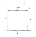
本実施形態に係る横架材2は、図1及び図2に示すように、隣接する支柱1の上端部間に配されるものである。そして、これら支柱1及び横架材2によって囲まれた空間を作業空間として他の空間と仕切り得るフレーム構造体X(空間構成設備)を構成している。このフレーム構造体X(空間構成設備)は、図1に示す構成を単位モジュールとし、このような単位モジュールを複数連接することが可能なものである。
As shown in FIGS. 1 and 2, the
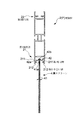
支柱1は、図1〜図4に示すように、概略円柱状をなす支柱本体11と、この支柱本体11の外方に取り付け可能な支柱用カバー12と、支柱本体11の下方に設けられる支柱用アジャスタ13とを備えたものである。
As shown in FIGS. 1 to 4, the
支柱本体11は、内壁111と、この内壁111の外方に離間して設けた外壁112と、これら内壁111及び外壁112を接続するリブ113とを備えた二重壁構造をなし、内壁111、外壁112、及びリブ113により区成される空洞11sを有する。さらに、外壁112には、空洞11sを外部に連通させるためのスリット11tを有する。このスリット11tは、所定間隔、本実施形態では45度又は略45度間隔で間欠的に設けている。また、このスリット11tから空洞11s内に配線などを挿入することによって、この空洞11sを配線挿通空間として使用可能にしている。支柱用カバー12は、支柱本体11の外壁112の外面と対向するカバー本体121と、このカバー本体121から内方に突出しスリット11tと係わり合い可能な係止部122とを備えたものである。なお、本実施形態では、図1に示すように、この支柱1を平面視矩形のコーナーに該当する箇所に起立姿勢で配置している。
The column
横架材2は、図1及び図2に示すように、直線状に延出する長尺のものであり、本実施形態では押出し成形により形成している。この横架材2は、複数種類のオプション部材が取付可能なものであり、図5に示すように、複数種類のオプション部材のうち一又は複数のオプション部材を取り付けるための第1取付部21と、第1取付部21に対して上下方向に離間し、且つ複数種類のオプション部材のうち前記第1取付部21に取付可能なオプション部材とは異なる他のオプション部材を取り付けるための第2取付部22とを備え、第1取付部21を下端部側に位置付けた第1姿勢(P)と、第2取付部22を下端部側に位置付けた第2姿勢(Q)との間で上下反転可能なものである。なお、図5には第1姿勢(P)にある横架材2を示している。第1取付部21及び第2取付部22は横架材2の高さ方向中央部を挟んだ対称位置に設けられており、以下、各取付部(第1取付部21、第2取付部22)の説明において、横架材2の高さ方向中央部側を「基端部」側とし、その反対側(高さ方向中央部から離間した側)を「先端部」側としている。なお、図5は、図4におけるx―x線端面図であり、作図上ハッチを省略している。
As shown in FIGS. 1 and 2, the
第1取付部21は、横架材2の厚み方向に対向する一対の第1対向壁211と、これら各第1対向壁211のうち相互に向き合う内向面に設けられオプション部材の一部が係わり合う一対の係わり合い部212と、第1姿勢(P)において下方に開口する第1開口部213とを備えたものである。一対の係わり合い部212は、第1開口部213の開口縁、換言すれば各第1対向壁211の先端部よりも横架材2の高さ方向中央部側へ寄った位置から相寄る方向に突出したものである。本実施形態では、第1取付部21を構成する一対の第1対向壁211を利用して、後述する取付部材J1が挿入可能な取付部材挿入空間23を形成している。取付部材挿入空間23は、前記係わり合い部212よりもさらに横架材2の高さ方向中央部側へ寄った位置において第1対向壁211同士を接続する第1接続壁231と、第1接続壁231よりもさらに横架材2の高さ方向中央部側へ寄った位置において第1対向壁211同士を接続する第2接続壁232と、一対の第1対向壁211とによって区成された空間である。なお、第2接続壁232を、各第1対向壁211の基端部よりも第1開口部213側に寄った位置に設けている。換言すれば、各第1対向壁211の基端部を第2接続壁232よりも横架材2の高さ方向中央部側へ突出させている。
The
一方、第2取付部22は、横架材2の厚み方向に対向する一対の第2対向壁221と、これら各第2対向壁221間に形成されオプション部材の一部又は全部が収容可能な収容部222と、第1姿勢(P)において上方に開口する第2開口部223とを備えたものである。この第2開口部223の開口方向は、横架材2の高さ方向に沿って前記第1開口部213の開口方向と反対である。収容部222は、第2開口部223の開口縁、換言すれば各第2対向壁221の先端部よりも横架材2の高さ方向中央部側へ寄った位置から相寄る方向に突出した一対の突出壁222aと一対の第2対向壁221とによって囲まれた収容スペース222sを有するものである。本実施形態では、第2対向壁221の先端部から突出壁222aまでの離間寸法を、前記第1取付部21における第1対向壁211の先端部から係わり合い部212までの離間寸法よりも大きく設定している。すなわち、突出壁222aを、係わり合い部212よりも相対的に横架材2の高さ方向中央部側に寄った位置に設け、収容スペース222sの奥行き寸法を大きく設定している。また、本実施形態では、第2開口部223の開口縁、換言すれば各第2対向壁221の先端部に、第2開口部223の開口寸法を狭める方向に突出し、オプション部材の一部が当接又は近接する一対の当たり部221aを設けている。この第2取付部22を構成する一対の第2対向壁221を利用して、後述する取付部材J1が挿入可能な取付部材挿入空間24を形成している。この取付部材挿入空間24は前述した取付部材挿入空間23と同一のものである。つまり、取付部材挿入空間24は、前記突出壁222aよりもさらに横架材2の高さ方向中央部側へ寄った位置において第2対向壁221同士を接続する第1接続壁241と、第1接続壁241よりもさらに横架材2の高さ方向中央部側へ寄った位置において第2対向壁221同士を接続する第2接続壁242と、一対の第2対向壁221とによって区成された空間である。なお、第2接続壁242を、各第2対向壁221の基端部よりも第2開口部223側に寄った位置に設けている。換言すれば、各第2対向壁221の基端部を第2接続壁242よりも横架材2の高さ方向中央部側へ突出させている。
On the other hand, the second mounting
対をなす第1対向壁211間の離間寸法と、対をなす第2対向壁221間の離間寸法とは、相互に同一又は略同一であるとともに、第1対向壁211の高さ寸法と、第2対向壁221の高さ寸法とは、相互に同一又は略同一である。すなわち、第1対向壁211及び第2対向壁221は、外見上同一又は略同一である。
The separation dimension between the pair of first opposing
横架材2は、第1対向壁211と第2対向壁221との間にスリット25を形成し、第1取付部21及び第2取付部22に取付可能なオプション部材とはさらに異なるオプション部材を、その一部を前記スリット25内に挿入した状態で取付可能に構成している。本実施形態では、前記第2接続壁232と前記第2接続壁242とを対をなす連結壁26によって連結している。そして、各第1対向壁211と各第2対向壁221との間にそれぞれスリット25を形成し、この一対のスリット25を、横架材2の厚み方向に相反する方向に開口する凹溝の開口縁とみなした場合、各連結壁26は各凹溝の底壁とみなすことができる。スリット25は横架材2の長手方向全域又は略全域に亘って連続して形成されている。スリット25の開口高さ寸法、換言すれば第1対向壁211の基端部と第2対向壁221の基端部との離間寸法は横架材2の長手方向全域又は略全域に亘って同一又は略同一である。
The
本実施形態では、図1及び図2に示すように、4本の横架材2をそれぞれ隣接する支柱1の上端部間に設け、これら横架材2及び支柱1によって立方体状をなすフレーム構造体Xを構成し、このフレーム構造体X(空間構成設備)に囲まれた空間を作業空間として区画するようにしている。
In this embodiment, as shown in FIGS. 1 and 2, four
支柱1と横架材2とは接続部Jを介して接続され、相互に拘束しあって自立性を確保している。
The
接続部Jは、図3及び図4等に示すように、横架材2の側端部に設けられ、支柱1に直接取り付けられる取付部材J1と、支柱1の内壁111に添接したナット部材J2と、取付部材J1を支柱1の内壁111及び外壁112を介してナット部材J2に緊締するための取付部材固定ボルトJ3とを備えたものである。
As shown in FIGS. 3 and 4, the connecting portion J is provided at the side end portion of the
取付部材J1は、支柱1の外壁112に当接可能な当接部J11と、この当接部J11から横架材2の長手方向に突出させて設けてなり前記横架材2の各取付部材挿入空間23、24に挿入可能な一対の横架材支持部J12と、支柱1のスリット11tに嵌合して支柱1に対する取付部材J1の周方向の位置決めを行うための嵌合凸部J13とを有する。
The mounting member J1 is provided with a contact portion J11 capable of contacting the
横架材支持部J12には、取付部材固定ボルトJ3をナット部材J2に螺着させた状態で取付部材固定ボルトJ3の頭部を収納するねじ頭収納部J12aと、支柱1に向かうとともにこの取付部材J1の高さ方向中央に向かい傾斜する方向に取付部材固定ボルトJ3を螺進退可能にすべく該方向に延伸するボルト挿通孔J12bとを上下両側に設けている。本実施形態では、一対の横架材支持部J12を、それぞれ上下反転させた姿勢で各取付部材挿入空間23、24にそれぞれ挿入しているため、上下のボルト挿通孔J12bは、取付部材固定ボルトJ3の軸心を支柱1の外面の法線に対して線対称となす方向にそれぞれ延伸している。
The horizontal member support portion J12 includes a screw head storage portion J12a for storing the head of the mounting member fixing bolt J3 in a state where the mounting member fixing bolt J3 is screwed to the nut member J2, and the mounting head fixing head J12. Bolt insertion holes J12b extending in this direction are provided on both upper and lower sides so that the mounting member fixing bolt J3 can be screwed back and forth in a direction inclined toward the center in the height direction of the member J1. In this embodiment, since the pair of horizontal member support portions J12 are respectively inserted into the attachment
嵌合凸部J13は、本実施形態では当接部J11の上下両端部から支柱1に向けて突出していて、上述したように、支柱1のスリット11tに嵌合して取付部材J1の支柱1の周方向の位置決めを行う。
In this embodiment, the fitting protrusion J13 protrudes from the upper and lower ends of the abutting portion J11 toward the
そして、横架材2の第1接続壁231、第1接続壁241にそれぞれ設けたねじ挿通孔231a、241aから挿入した雄ねじJ14を、横架材支持部J12に形成した雌ねじ孔J12cにねじ込むことによって取付部材J1と横架材2とを一体的に取り付けている。
Then, the male screw J14 inserted from the
ナット部材J2は、支柱1の内壁111に添接させてなり取付部材固定ボルトJ3と螺合可能な雌ねじ孔J21aを有するナット部材本体J21と、このナット部材本体J21の上端から延伸して設けてなり、支柱1の内壁111の上端部に引っ掛けることが可能な係止爪J22とを具備する。前記雌ねじ孔J21aは、上下一対に設けている。
The nut member J2 is attached to the
そして、取付部材J1のボルト挿通孔J12bに挿入した取付部材固定ボルトJ3の軸部をナット部材J2の雌ねじ孔J21aにねじ込むことにより、ナット部材J2の本体J21と支柱1の内壁111とが互いに圧着するとともに、取付部材J1の当接部J11と支柱1の外壁112とが互いに圧接し、取付部材固定ボルトJ3の締着が緩むのを抑制し、支柱1と横架材2とが強固に連結される。
Then, by screwing the shaft portion of the mounting member fixing bolt J3 inserted into the bolt insertion hole J12b of the mounting member J1 into the female screw hole J21a of the nut member J2, the main body J21 of the nut member J2 and the
しかして、本実施形態の横架材2は、前記第1取付部21を下端部側に位置付けた第1姿勢(P)と、前記第2取付部22を下端部側に位置付けた第2姿勢(Q)との間で上下反転可能なものであり、取り付けるオプション部材に応じて、第1姿勢(P)又は第2姿勢(Q)の何れかの姿勢で支柱1の上端部間に設けられる。
Thus, the
第1姿勢(P)で支柱1の上端部間に配された横架材2に取付可能なオプション部材としては、図6に示す可動パネル3が挙げられる。
As an optional member that can be attached to the
可動パネル3は、可動パネル本体31と、可動パネル本体31の上端部に設けられ第1取付部21の係わり合い部212に係合可能な可動パネル取付具32と、可動パネル本体31の下端部に設けられ床面に接地可能なアジャスタ33とを備えたものである。本実施形態では、可動パネル本体31の上端部及び下端部にそれぞれ複数の可動パネル取付具32及びアジャスタ33を適宜の固定手段により一体的に固着している。
The movable panel 3 includes a
可動パネル取付具32は、概略円柱状をなし、外周面の一部に下方に向かって漸次径寸法を小さく設定したテーパ面32aを有する。可動パネル取付具32の先端部は部分球状をなし、この先端部近傍に第1取付部21の一対の係わり合い部212に引っ掛かり得る鍔部32bを設けている。
The
そして、可動パネル3を移動不能な状態にするには、アジャスタ33を調節して可動パネル本体31を上方へ移動させ、可動パネル取付具32のテーパ面32aをそれぞれ係わり合い部212の先端部に圧接させる。この際、テーパ面32a自体が弾性変形しながら各係わり合い部212の先端部に圧接することにより、テーパ面32aと係わり合い部212と間に大きな摩擦抵抗が生じ、この摩擦抵抗により、可動パネル取付具32、ひいては可動パネル3全体が横架材2の長手方向に沿ってスライド移動不能な状態となる。一方、可動パネル3をスライド移動させる場合には、アジャスタ33を調節して可動パネル本体31を下方へ移動させ、可動パネル取付具32のテーパ面32aと係わり合い部212との圧接状態を解除する。これにより、可動パネル取付具32、ひいては可動パネル3全体が横架材2の長手方向に沿ってスライド移動可能な状態となる。可動パネル取付具32、ひいては可動パネル3全体を横架材2の長手方向に沿ってスライド移動させる際、可動パネル取付具32の鍔部32bが係わり合い部212の上方又は係わり合い部212に接触した位置でこれら係わり合い部212を跨いだ状態となり、横架材2の長手方向全域又は略全域に亘って延伸するこれら一対の係わり合い部212が、オプション部材(可動パネル3)をスライド移動可能に支持するスライド移動案内部として機能する。また、鍔部32bが係わり合い部212を跨いだ状態で係わり合い部212の上方又は係わり合い部212に接触した位置に位置付けられるため、可動パネル3に対して起立姿勢を崩す方向に不意な外力が作用しても、鍔部32bが係わり合い部212に引っ掛かることによって可動パネル取付具32、ひいては可動パネル3全体が横架材2から抜け外れるという事態を回避することができる。なお、可動パネル3を横架材2に取り付ける際には、可動パネル3をある程度大きく傾斜させて可動パネル取付具32の鍔部32bを係わり合い部212の先端部同士の隙間に挿入しながら順次起立姿勢に近付けていくことにより行う。可動パネル3を第1取付部21に取り付けた状態において、可動パネル取付具32は、第1開口部213の開口縁よりも奥方(上方)であって、且つ第1対向壁211同士の間に位置付けられ、外部から視認し難い又は視認不能なものとなる。
In order to make the movable panel 3 immovable, the
可動パネル本体31として、図6に示すようなパネル面がフラットなものや、水平軸回りに回転可能な羽板状のルーバーを高さ方向に所定ピッチで有するもの(図示省略)、或いは収納ボックスや収納トレー等の収納具を所定高さ位置に設けたもの(図示省略)等、種々のタイプのものを適用しても構わない。
The
また、第1姿勢(P)で支柱1の上端部間に配された横架材2に取付可能なオプション部材としては、可動パネル3の他に、図7に示す簾状のスクリーン(以下「簾スクリーン4」と称す)や、図8に示すロールスクリーン5が挙げられる。
Further, as an optional member that can be attached to the
簾スクリーン4は、幕状の簾スクリーン本体41と、簾スクリーン本体41の上端部に設けられ第1取付部21の係わり合い部212に係合可能な簾スクリーン取付具42とを備えたものである。本実施形態では、簾スクリーン4を横架材2に取り付けた状態で簾スクリーン本体41の下端部が床面から所定距離離間するように簾スクリーン本体41の高さ寸法を設定している。簾スクリーン本体41の全幅に亘って簾スクリーン取付具42を設けている。
The eaves screen 4 includes a curtain-like eaves screen
簾スクリーン取付具42は、押出し成形により形成された樹脂製のものであり、第1取付部21の対をなす係わり合い部212を跨ぎ、且つ対向する第1対向壁211の内向面に当接又は近接した状態で係わり合い部212に引っ掛け可能な下向き部分円弧状の引っ掛け部42aと、引っ掛け部42aの中央位置に設けられ簾スクリーン本体41の上端部に設けた掛け具41aを保持し得る保持部42bとを備えたものである。この簾スクリーン取付具42を第1取付部21に取り付けるには、簾スクリーン取付具42を第1開口部213の下方から上方に向かって押圧して、一対の係わり合い部212に下方から当たる過程で弾性変形させ、一対の係わり合い部212を乗り越えた時点で弾性復帰力により対向する第1対向壁211の内向面に当接又は近接した状態で係わり合い部212に引っ掛けることにより行う。簾スクリーン4を第1取付部21に取り付けた状態において、簾スクリーン取付具42は、第1開口部213の開口縁よりも奥方(上方)であって、且つ第1対向壁211同士の間に位置付けられ、外部から視認し難い又は視認不能なものとなる。
The
ロールスクリーン5は、ロールスクリーン本体51と、ロールスクリーン本体51に付属の専用取付金具52と、専用取付金具52に適宜の固定手段により一体的に取り付けられ且つ第1取付部21の係わり合い部212に係合可能なロールスクリーン取付具53とを備えたものである。本実施形態では、ロールスクリーン本体51の上端部に前記専用取付金具52を所定ピッチ離間させて設け、これら各専用取付金具52にそれぞれロールスクリーン取付具53を適宜の固定手段により一体的に固着している。
The roll screen 5 is integrally attached to the roll screen
ロールスクリーン取付具53は、対をなす係わり合い部212の先端部同士の離間寸法より僅かに小さい径寸法を有する小径円柱部53aと、対をなす係わり合い部212の先端部同士の離間寸法より大きい径寸法を有し、対をなす係わり合い部212を上方から跨いだ状態で係わり合い部212に引っ掛け可能な大径円盤部53bとを一体に有するものである。このロールスクリーン取付具53を係わり合い部212の長手方向(横架材2の長手方向)に沿ってスライド移動させることにより、ロールスクリーン5全体が横架材2の長手方向にスライド移動させることが可能である。ロールスクリーン5を第1取付部21に取り付けた状態において、ロールスクリーン取付具52は、第1開口部213の開口縁よりも奥方(上方)であって、且つ第1対向壁211同士の間に位置付けられ、外部から視認し難い又は視認不能なものとなる。
The roll
また、図8に示すように、横架材2が第1姿勢(P)にある場合、上方に開口する第2開口部223を有する第2取付部22に、展開したロールスクリーン本体51を照らし得るスポットライトLを取り付けてもよい。スポットライトLは、第2取付部22の収容部222に載置した状態で収容されたスポットライト取付具L1と、スポットライト取付具L1から横架材2の厚み方向に向かって延伸し先端部を下方に向かって傾斜させたアーム部L2と、アーム部L2の先端部に設けたスポットライト本体L3とを備えたものである。スポットライト取付具L1は、ロールスクリーン本体51よりも幅寸法を小さく設定したものであり、このスポットライト取付具L1を収容部222に収容した状態(第1接続壁241に載置した状態)で一対の第2対向壁221にガイドさせながら横架材2の長手方向に沿ってスライド移動させることにより、スポットライトL全体が横架材2の長手方向にスライド移動させることが可能である。スポットライト本体L3は、展開したロールスクリーン本体51を照明する方向に向けられている。
Further, as shown in FIG. 8, when the
一方、第2姿勢(Q)で支柱1の上端部間に配された横架材2に取付可能なオプション部材としては、図9〜図11に示す各種固定パネル(クリアパネル6、ホワイトボードパネル7、タッカブルパネル8)が挙げられる。
On the other hand, as an optional member that can be attached to the
これら各種固定パネル(クリアパネル6、ホワイトボードパネル7、タッカブルパネル8)を横架材2に取り付けるに際しては、予め、支柱1の下端部間に下部横架材9を取り付けている。下部横架材9は、押出し成形により形成され、上方及び下方に向かって開口する上方開口部91及び下方開口部92を有する概略角筒状のものである。下部横架材9の厚み方向に対向する一対の対向壁93間の離間寸法を、第2対向壁221間の離間寸法と同一又は略同一に設定するとともに、本実施形態では、上方開口部91の開口縁、換言すれば各対向壁93の上端部に、上方開口部91の開口寸法を狭める方向に突出し、オプション部材の一部が当接又は近接する一対の当たり部93aを設けている。各当たり部93aの突出端部間の離間寸法を、第2取付部22の前記当たり部221aの突出端部間の離間寸法と同一又は略同一に設定している。下部横架材9は、各当たり部93aよりも下方に寄った位置に対向壁93同士を接続する接続壁94を備え、この接続壁94が、オプション部材(クリアパネル6、ホワイトボードパネル7、タッカブルパネル8)の下端部を載置した状態で支持する支持壁として機能する。なお、下部横架材9自体は、床面から離間した位置に配されるものであり、下部横架材9の下端部に所定ピッチで下部横架材用アジャスタ95を設けている。
When these various fixed panels (clear panel 6, whiteboard panel 7, tackable panel 8) are attached to the
各固定パネル(クリアパネル6、ホワイトボードパネル7、タッカブルパネル8)は、横架材2と下部横架材9との間に取付可能なものである。
Each fixed panel (clear panel 6, whiteboard panel 7, tackable panel 8) can be attached between the
クリアパネル6は、例えばアクリル樹脂製の薄型(例えば厚み寸法5mm)のクリアパネル本体61と、クリアパネル本体61の上端部及び下端部をそれぞれ挟持し且つ収容部222に収容可能な上下一対のクリアパネル取付具62とを備えたものである。各クリアパネル取付具62は、クリアパネル本体61の挟持可能な一対の挟持部62aと、対をなす当たり部221a(又は対をなす当たり部93a)に挟持される被挟持部62bとを備えたものである。このようなクリアパネル6を横架材2と下部横架材9との間に取り付ける作業は、先ず、クリアパネル6を所定角度傾斜させた状態で、上側のクリアパネル取付具62を第2取付部22の第2開口部223から収容部222内に収容させながら上方へ持ち上げつつ、クリアパネル6全体を徐々に起立姿勢に近付け、引き続き、下側のクリアパネル取付具62を下部横架材9の上方開口部91に上方から落とし込む一連の作業、いわゆるけんどん方式によって行う。このような作業により横架材2と下部横架材9との間にクリアパネル6を取り付けた状態において、各クリアパネル取付具62の被挟持部62bがそれぞれ対をなす当たり部221a又は対をなす当たり部93aに挟持されるため、クリアパネル6全体がガタツキの無い状態で横架材2と下部横架材9との間に保持される。また、クリアパネル取付具62の被挟持部62bに、対をなす当たり部221a又は対をなす当たり部93aに当接し、且つ第2開口部223に挿入する際又は上方開口部91に挿入する際に当たり部221a又は当たり部93aに添接し得る一対のガイド壁62cを設けている。
The clear panel 6 includes, for example, a thin
ホワイトボードパネル7は、例えば第2開口部223の開口縁における開口寸法、換言すれば対をなす当たり部221aの突出部同士間の離間寸法より若干小さい厚み寸法を有するホワイトボードパネル本体71を主体としてなり、前記けんどん方式によって横架材2と下部横架材9との間に取付可能なものである。横架材2と下部横架材9との間にホワイトボードパネル7を取り付けた状態において、ホワイトボードパネル本体71の上端部及び下端部がそれぞれ対をなす当たり部221a又は対をなす当たり部93aに挟持されるため、ホワイトボードパネル7全体がガタツキの無い状態で横架材2と下部横架材9との間に保持される。
The whiteboard panel 7 is mainly composed of a whiteboard panel
タッカブルパネル8は、例えば第2開口部223の開口縁における開口寸法、換言すれば対をなす当たり部221aの突出部同士間の離間寸法より若干小さい厚み寸法を有するタッカブルパネル本体81を主体としてなり、前記けんどん方式によって横架材2と下部横架材9との間に取付可能なものである。横架材2と下部横架材9との間にタッカブルパネル8を取り付けた状態において、タッカブルパネル本体81の上端部及び下端部がそれぞれ対をなす当たり部221a又は対をなす当たり部93aに挟持されるため、タッカブルパネル8全体がガタツキの無い状態で横架材2と下部横架材9との間に保持される。なお、タッカブルパネル8とは、パネル面に資料やメモ等をピンで留めることが可能なパネルのことである。
The tackable panel 8 is mainly composed of a
さらに、第2姿勢(Q)で支柱1の上端部間に配された横架材2に取付可能なオプション部材としては、横架材2の長手方向に沿ってスライド移動可能な照明装置(図示省略)が挙げられる。この照明装置は、第2取付部22の収容部222に収容されるライティングレールと、ライティングレールに支持される照明本体とを備えたものが挙げられる。
Further, as an optional member that can be attached to the
本実施形態に係る横架材2は、第1対向壁211と前記第2対向壁221との間に形成したスリット25を利用して、前述した各オプション部材とは異なる他のオプション部材、具体的には、図12に示すように、平面視において対向する横架材2同士の間に架けられる中間フレームAを取付可能に構成している。
The
中間フレームAは、押出し成形により形成した長尺の中間フレーム本体A1と、中間フレーム本体A1の両端部にそれぞれ設けた中間フレーム取付具A2とを備えたものである。中間フレーム本体A1は、概略四角筒状をなし、少なくとも下向面の厚み方向中央部に開口凹部A11を形成している。また、中間フレーム本体A1の高さ寸法を、横架材2の高さ寸法の半分より若干小さい寸法に設定している。中間フレーム取付具A2は、中間フレーム本体A1の側端面に一体的に設けられ、起立壁A211、起立壁A211の上端に形成した下向きL字状の上部引っ掛け部A212、及び起立壁A211の下端部近傍部位であって前記中間フレーム本体A1の開口凹部A11内に位置付けられるネジ軸A213とを有する中間フレーム第1取付具A21と、前記開口凹部A11内に収まる幅寸法及び高さ寸法に設定し、且つ幅中央部に高さ方向に延びる長孔A221aを形成した起立壁A221、及び起立壁A221の下端に形成した上向きL字状の下部引っ掛け部A222を有する中間フレーム第2取付具A22と、ネジ軸A213に螺合可能なナットA23とを備えたものである。
The intermediate frame A includes a long intermediate frame main body A1 formed by extrusion molding, and intermediate frame attachments A2 provided at both ends of the intermediate frame main body A1, respectively. The intermediate frame main body A1 has a substantially rectangular tube shape, and an opening recess A11 is formed at least in the center in the thickness direction of the downward surface. Further, the height dimension of the intermediate frame main body A1 is set to be slightly smaller than half the height dimension of the
このような中間フレームAを横架材2のスリット25を利用して取り付ける手順を説明する。なお、中間フレームAは、スリット25及び第1対向壁211を利用して横架材2に取り付けることが可能であるとともに、スリット25及び第2対向壁221を利用して横架材2に取り付けることも可能である。図12では、スリット25及び第2対向壁221を利用して第1姿勢(P)にある横架材2の上半部側に中間フレームAを取り付けた態様を示しており、この場合の取付手順について説明する。予め中間フレームAの開口凹部A11に位置付けられるネジ軸A213に長孔A221aを通し、中間フレーム第1取付具A21に中間フレーム第2取付具A22を高さ方向に移動自在な状態で支持させておく。そして、中間フレーム第1取付具A21の上部引っ掛け部A212を第2対向壁221の先端部に引っ掛け、次いで、スリット25内に挿入した中間フレーム第2取付具A22の下部引っ掛け部A222を第2対向壁221の基端部に引っ掛かる位置までこの中間フレーム第2取付具A22を上方へ移動させる。この状態、つまり、上部引っ掛け部A212及び下部引っ掛け部A222をそれぞれ第2対向壁221の先端部及び基端部に引っ掛けた状態で、ネジ軸A213にナットA23を螺合させて締め付けることにより、中間フレーム第2取付具A22が中間フレーム第1取付具A21に対して移動不能に固定される。以上の手順により、中間フレームAを横架材2にガタツキの無い状態で取り付けることができる。なお、中間フレームAの開口凹部A11内において露出するナットA23及びネジ軸A213を図示しないキャップによって被覆しても構わない。
A procedure for attaching such an intermediate frame A using the
また、スリット25及び第1対向壁211を利用して第1姿勢(P)にある横架材2の下半部側に中間フレームAを取り付ける場合も上記手順に準じて行うことができ、スリット25に挿入した上部引っ掛け部A212を第1対向壁211の基端部に引っ掛けるとともに、下部引っ掛け部A222を第2対向壁221の先端部に引っ掛けた状態で、ネジ軸A213にナットA23を螺合させて締め付けることにより、中間フレームAを横架材2にガタツキの無い状態で取り付けることができる。
Further, when the intermediate frame A is attached to the lower half side of the
もちろん、第2姿勢(Q)にある横架材2にも、スリット25を利用して中間フレームAを取り付けることが可能である。第2姿勢(Q)にある横架材2の上半部側に横架材2を取り付ける場合には、上部引っ掛け部A212を第1対向壁211の先端部に引っ掛けるとともに、スリット25に挿入した下部引っ掛け部A222を第1対向壁211の基端部に引っ掛ける態様となり、第2姿勢(Q)にある横架材2の下半部側に横架材2を取り付ける場合には、スリット25に挿入した上部引っ掛け部A212を第2対向壁221の基端部に引っ掛けるとともに、下部引っ掛け部A222を第2対向壁221の先端部に引っ掛ける態様となる。
Of course, it is possible to attach the intermediate frame A to the
また、対向する横架材2に架設した中間フレームAは、ネジ軸A213とナットA23とによる締付状態を解除することにより、中間フレーム第2取付具A22が下方に移動して下部引っ掛け部A222の引っ掛け状態も解除され、中間フレームAが横架材2の長手方向に沿ってスライド移動可能な状態となる。そして、使用態様やレイアウト変更等に応じて中間フレームAを横架材2の長手方向に移動させ、所望の位置に到達させた時点で、下部引っ掛け部A222が引っ掛け状態となる位置まで中間フレーム第2取付具A22を上方に移動させて、ネジ軸A213とナットA23とを再度締め付けることにより、中間フレームAはスライド移動不能な状態となる。このように、中間フレームAの取付位置を変更可能に構成することにより、中間フレームAに照明装置や各種パネル等のオプション部材を取り付けた状態で中間フレームAをスライド移動させた場合には、照明装置や各種パネル等のオプション部材の配置位置も簡単に変更することができる。
Further, the intermediate frame A installed on the opposite
このように、本実施形態に係る横架材2は、複数種類のオプション部材のうち一又は複数のオプション部材(可動パネル3、簾スクリーン4、ロールスクリーン5)を取り付けるための第1取付部21と、第1取付部21に対して上下方向に離間し、第1取付部21に取付可能なオプション部材とは異なる他のオプション部材(クリアパネル6、ホワイトボードパネル7、タッカブルパネル8、照明装置)を取り付けるための第2取付部22とを備えて、取り付けるオプション部材に応じて、第1取付部21を下端部側に位置付けた第1姿勢(P)と、第2取付部22を下端部側に位置付けた第2姿勢(Q)との間で上下反転可能なものであるため、第1取付部21に取付可能なオプション部材(可動パネル3、簾スクリーン4、ロールスクリーン5)を横架材2に取り付ける場合には、横架材2を第1姿勢(P)の状態で支柱1の上端部間に配置すればよく、一方、第2取付部22に取付可能なオプション部材(クリアパネル6、ホワイトボードパネル7、タッカブルパネル8、照明装置)を横架材2を取り付ける場合には、横架材2を上下反転させて第2姿勢(Q)の状態で支柱1の上端部間に配置すればよく、横架材2に取り付けるオプション部材の種類が多種に亘る場合であっても、全てのオプション部材が同一の取付対象部(単一の取付部)にのみ取付可能なものでなければならないという設計上の制約が生じず、取付構造が異なる複数種類のオプション部材を、横架材2を上下反転させることにより好適に取り付けることができる。
As described above, the
特に、第1取付部21が、厚み方向に対向する一対の第1対向壁211と、これら各第1対向壁211の内向面に設けられオプション部材の一部、具体的には、可動パネル取付具32、簾スクリーン取付具42、ロールスクリーン取付具53が係わり合う係わり合い部212とを備えたものであり、第2取付部22が、厚み方向に対向する一対の第2対向壁221と、これら各第2対向壁221間に形成されオプション部材の一部又は全部、具体的には、クリアパネル取付具62、ホワイトボードパネル本体71の上端部、タッカブルパネル本体81の上端部、照明装置のライティングレールが収容可能な収容部222とを備えているため、これら係わり合い部212及び収容部222を利用して各オプション部材の良好な取付状態を確保することができるとともに、オプション部材の取付に積極的に寄与するこれら係わり合い部212及び収容部222がそれぞれ対をなす第1対向壁211、第2対向壁221によって外部から視認できない又は視認しづらいため、看者に煩雑な印象を与えないシンプルな外観を呈するものとなる。
In particular, the first mounting
さらに、横架材2の長手方向に沿った全域又は略全域に設けた一対の係わり合い部212が、オプション部材(可動パネル3、ロールスクリーン5)をスライド移動可能に支持するスライド移動案内部としても機能するものであり、別途専用のスライド移動案内部を設ける必要がなく、構造の簡略化及びコストの削減に資する。
Furthermore, a pair of engaging
加えて、第1対向壁211及び前記第2対向壁221が、外見上同一又は略同一であるため、支柱1の上端部間に横架材2を第1姿勢(P)、第2姿勢(Q)、何れの姿勢で支持させても、外見上に差異が表れず、例えば、複数の横架材2を配設したオフィス空間において、各横架材2の姿勢が異なっていても看者に煩雑な印象を与えることがなく、統一された外観を呈するものとなる。
In addition, since the first opposing
また、第1対向壁211と第2対向壁221との間にスリット25を形成し、各第1対向壁211単体及び各第2対向壁221単体に、第1取付部21及び第2取付部22に取付可能なオプション部材とはさらに異なるオプション部材、具体的には中間フレームAを、その一部をスリット25内に挿入した状態で取付可能に構成しているため、第1取付部21に取付可能なオプション部材や第2取付部22に取付可能なオプション部材とはさらに異なるオプション部材である中間フレームAを横架材2に取り付けることが可能となり、種々の使用態様にも柔軟に対応することができる。
Moreover, the
なお、本発明は、以上に詳述した実施形態に限られるものではない。 The present invention is not limited to the embodiment described in detail above.
例えば、横架材として、平面視部分円弧状(例えば4分の1円弧状等)のものを適用してもよい。このような横架材を複数用いることにより平面視円形状のフレーム構造体(空間構成設備)を形成することが可能となる。 For example, as the horizontal member, a partial arc shape in plan view (for example, a quarter arc shape) may be applied. By using a plurality of such horizontal members, it is possible to form a frame structure (space constituting equipment) having a circular shape in plan view.
また、横架材は、高さ方向に離間して設けた第1取付部及び第2取付部を備えたものであればよく、横断面円形状又は略円形状、或いは横断面楕円形状又は略楕円形状のものであって構わない。 Further, the horizontal member may be provided with a first mounting portion and a second mounting portion that are provided apart in the height direction, and has a circular cross section or a substantially circular shape, or an elliptical cross section or a substantially cross section. It may be oval.
また、オプション部材として、前記実施形態で例示したもの以外のものを適用しても構わない。 Moreover, you may apply the thing other than what was illustrated by the said embodiment as an option member.
その他、各部の具体的構成についても上記実施形態に限られるものではなく、本発明の趣旨を逸脱しない範囲で種々変形が可能である。 In addition, the specific configuration of each part is not limited to the above embodiment, and various modifications can be made without departing from the spirit of the present invention.
1…支柱
2…横架材
21…第1取付部
211…第1対向壁
212…係わり合い部
22…第2取付部
221…第2対向壁
222…収容部
25…スリット
3、4、5、6、7、8、A…オプション部材(可動パネル、簾スクリーン、ロールスクリーン、クリアパネル、ホワイトボードパネル、タッカブルパネル、中間フレーム)
DESCRIPTION OF
Claims (5)
前記複数種類のオプション部材のうち一又は複数のオプション部材を取り付けるための第1取付部と、
当該第1取付部に対して上下方向に離間し、且つ前記複数種類のオプション部材のうち前記第1取付部に取付可能なオプション部材とは異なる他のオプション部材を取り付けるための第2取付部とを備えてなり、
取り付けるオプション部材に応じて、前記第1取付部を下端部側に位置付けた第1姿勢と、前記第2取付部を下端部側に位置付けた第2姿勢との間で上下反転可能なものであることを特徴とする横架材。 A horizontal member that is arranged between the upper ends of adjacent struts and that can be attached with a plurality of types of optional members,
A first mounting portion for mounting one or more option members among the plurality of types of option members;
A second mounting portion for mounting another option member that is spaced apart from the first mounting portion in the vertical direction and is different from an option member that can be mounted on the first mounting portion among the plurality of types of option members; With
Depending on the option member to be mounted, the first mounting portion can be turned upside down between a first posture in which the first mounting portion is positioned on the lower end side and a second posture in which the second mounting portion is positioned on the lower end side. A horizontal material characterized by that.
前記第2取付部が、厚み方向に対向する一対の第2対向壁と、これら各第2対向壁間に形成されオプション部材の一部又は全部が収容可能な収容部とを備えたものである請求項1記載の横架材。 The first mounting portion includes a pair of first opposing walls opposed to each other in the thickness direction, and an engaging portion provided on an inward surface of each of the first opposing walls with which a part of an optional member is engaged. ,
The second mounting portion includes a pair of second opposing walls opposed to each other in the thickness direction, and an accommodating portion that is formed between the second opposing walls and that can accommodate part or all of the optional member. The horizontal member according to claim 1.
An option that allows a slit to be formed between the first opposing wall and the second opposing wall, and can be attached to each of the first opposing wall and each second opposing wall to the first mounting portion and the second mounting portion. The horizontal member according to claim 2, 3, or 4, wherein an optional member further different from the member can be attached in a state in which a part thereof is inserted into the slit.
Priority Applications (1)
| Application Number | Priority Date | Filing Date | Title |
|---|---|---|---|
| JP2008197893A JP5303734B2 (en) | 2008-07-31 | 2008-07-31 | Horizontal material |
Applications Claiming Priority (1)
| Application Number | Priority Date | Filing Date | Title |
|---|---|---|---|
| JP2008197893A JP5303734B2 (en) | 2008-07-31 | 2008-07-31 | Horizontal material |
Publications (2)
| Publication Number | Publication Date |
|---|---|
| JP2010037715A true JP2010037715A (en) | 2010-02-18 |
| JP5303734B2 JP5303734B2 (en) | 2013-10-02 |
Family
ID=42010547
Family Applications (1)
| Application Number | Title | Priority Date | Filing Date |
|---|---|---|---|
| JP2008197893A Active JP5303734B2 (en) | 2008-07-31 | 2008-07-31 | Horizontal material |
Country Status (1)
| Country | Link |
|---|---|
| JP (1) | JP5303734B2 (en) |
Citations (4)
| Publication number | Priority date | Publication date | Assignee | Title |
|---|---|---|---|---|
| JP2002138609A (en) * | 2000-11-01 | 2002-05-17 | Okamura Corp | Connecting rod for connecting panel, and partition device using the same |
| JP2004084231A (en) * | 2002-08-26 | 2004-03-18 | Kokuyo Co Ltd | Partition structure |
| JP2004183248A (en) * | 2002-11-29 | 2004-07-02 | Itoki Crebio Corp | Space forming structure |
| JP2005171655A (en) * | 2003-12-12 | 2005-06-30 | Kokuyo Co Ltd | Partition structure for frame structure |
-
2008
- 2008-07-31 JP JP2008197893A patent/JP5303734B2/en active Active
Patent Citations (4)
| Publication number | Priority date | Publication date | Assignee | Title |
|---|---|---|---|---|
| JP2002138609A (en) * | 2000-11-01 | 2002-05-17 | Okamura Corp | Connecting rod for connecting panel, and partition device using the same |
| JP2004084231A (en) * | 2002-08-26 | 2004-03-18 | Kokuyo Co Ltd | Partition structure |
| JP2004183248A (en) * | 2002-11-29 | 2004-07-02 | Itoki Crebio Corp | Space forming structure |
| JP2005171655A (en) * | 2003-12-12 | 2005-06-30 | Kokuyo Co Ltd | Partition structure for frame structure |
Also Published As
| Publication number | Publication date |
|---|---|
| JP5303734B2 (en) | 2013-10-02 |
Similar Documents
| Publication | Publication Date | Title |
|---|---|---|
| JP3992726B1 (en) | Clip and light source device | |
| JP2008081056A (en) | Instrument support stand | |
| US20060126276A1 (en) | Mounting structure of display panel | |
| JP2005114838A (en) | Liquid crystal module and liquid crystal display device | |
| JP5303734B2 (en) | Horizontal material | |
| JP6529816B2 (en) | Lighting fixture, mounting bracket and mounting bracket set | |
| JP5315539B2 (en) | Frame structure | |
| US8144268B2 (en) | Display device | |
| KR200442669Y1 (en) | Fixture for Combination Type Shelf | |
| JP2005299954A (en) | Stand for air conditioner | |
| JP3734991B2 (en) | Ventilator mounting device | |
| JP3594368B2 (en) | Faucet fittings | |
| JP2017050127A (en) | Lighting device | |
| JP4996540B2 (en) | Floor support legs | |
| JP3040257U (en) | Lighting equipment | |
| JP5231037B2 (en) | Panel fixture | |
| JP2008163963A (en) | Leg portion mounting structure and table using the same | |
| JP4518934B2 (en) | Fixture for electrical parts | |
| JP2008119738A (en) | Welding stud | |
| JP7331464B2 (en) | lighting equipment | |
| JP2005299953A (en) | Stand for air conditioner | |
| JP2017113351A (en) | Fastening structure of bathroom member | |
| JP3128601U (en) | Screw, screw head mounting member that can be mounted on the head of the screw, and screw unit | |
| JP3129224U (en) | table | |
| JP2005100863A (en) | Illumination fixture |
Legal Events
| Date | Code | Title | Description |
|---|---|---|---|
| A621 | Written request for application examination |
Free format text: JAPANESE INTERMEDIATE CODE: A621 Effective date: 20110621 |
|
| A977 | Report on retrieval |
Free format text: JAPANESE INTERMEDIATE CODE: A971007 Effective date: 20121011 |
|
| A131 | Notification of reasons for refusal |
Free format text: JAPANESE INTERMEDIATE CODE: A131 Effective date: 20121023 |
|
| A521 | Request for written amendment filed |
Free format text: JAPANESE INTERMEDIATE CODE: A523 Effective date: 20121221 |
|
| TRDD | Decision of grant or rejection written | ||
| A01 | Written decision to grant a patent or to grant a registration (utility model) |
Free format text: JAPANESE INTERMEDIATE CODE: A01 Effective date: 20130521 |
|
| A61 | First payment of annual fees (during grant procedure) |
Free format text: JAPANESE INTERMEDIATE CODE: A61 Effective date: 20130603 |
|
| R150 | Certificate of patent or registration of utility model |
Ref document number: 5303734 Country of ref document: JP Free format text: JAPANESE INTERMEDIATE CODE: R150 Free format text: JAPANESE INTERMEDIATE CODE: R150 |
|
| S111 | Request for change of ownership or part of ownership |
Free format text: JAPANESE INTERMEDIATE CODE: R313113 |
|
| SZ03 | Written request for cancellation of trust registration |
Free format text: JAPANESE INTERMEDIATE CODE: R313Z03 |
|
| R350 | Written notification of registration of transfer |
Free format text: JAPANESE INTERMEDIATE CODE: R350 |
|
| S111 | Request for change of ownership or part of ownership |
Free format text: JAPANESE INTERMEDIATE CODE: R313111 |
|
| R350 | Written notification of registration of transfer |
Free format text: JAPANESE INTERMEDIATE CODE: R350 |
|
| R250 | Receipt of annual fees |
Free format text: JAPANESE INTERMEDIATE CODE: R250 |
|
| R250 | Receipt of annual fees |
Free format text: JAPANESE INTERMEDIATE CODE: R250 |