JP2010036831A - Interior structure of vehicle equipped with curtain airbag - Google Patents
Interior structure of vehicle equipped with curtain airbag Download PDFInfo
- Publication number
- JP2010036831A JP2010036831A JP2008205046A JP2008205046A JP2010036831A JP 2010036831 A JP2010036831 A JP 2010036831A JP 2008205046 A JP2008205046 A JP 2008205046A JP 2008205046 A JP2008205046 A JP 2008205046A JP 2010036831 A JP2010036831 A JP 2010036831A
- Authority
- JP
- Japan
- Prior art keywords
- curtain
- curtain member
- vehicle
- pillar
- vehicle body
- Prior art date
- Legal status (The legal status is an assumption and is not a legal conclusion. Google has not performed a legal analysis and makes no representation as to the accuracy of the status listed.)
- Granted
Links
Images


Abstract
Description
この発明は、カーテンエアバッグを備えた車両の内装構造に関し、特に、収納状態でルーフトリム内に設置されるカーテンエアバッグを備えた車両の内装構造に関する。 The present invention relates to an interior structure of a vehicle provided with a curtain airbag, and more particularly to an interior structure of a vehicle provided with a curtain airbag installed in a roof trim in a stored state.
従来より、車両の側面衝突時やロールオーバー時において、車室内の天井部から下方にカーテン状に展開されるエアバッグ(以下、カーテン部材)を備えるカーテンエアバッグ装置が知られている。このカーテンエアバッグ装置においては、側面衝突時の衝撃を緩和すると共に、ロールオーバー時にはサイドウィンドを覆って乗員を保護するように構成している。 2. Description of the Related Art Conventionally, a curtain airbag device including an airbag (hereinafter referred to as a curtain member) that is deployed in a curtain shape downward from a ceiling portion in a vehicle compartment at the time of a side collision or rollover of a vehicle is known. This curtain airbag device is configured so as to mitigate the impact at the time of a side collision and to protect the occupant by covering the side window at the time of rollover.
例えば、下記特許文献1には、収納状態のカーテン部材をルーフサイドレール部のルーフトリム内に設置したカーテンエアバッグ装置が開示されている。
このカーテンエアバッグ装置では、カーテン部材の端部のピラートリム側への収納量を、展開時の引き込み移動量よりも少なく設定することで、収納時におけるルーフトリムの車室内側への膨らみを少なくしつつも、カーテン部材の展開時の展開性能を確実に維持するようにしている。
In this curtain airbag device, the amount of storage of the end of the curtain member on the pillar trim side is set to be smaller than the amount of pull-in movement during deployment, thereby reducing the swelling of the roof trim toward the vehicle interior during storage. However, the deployment performance when the curtain member is deployed is reliably maintained.
ところで、ルーフトリム内に収納されるカーテンエアバッグ装置においては、カーテン部材の側端部(車両前後方向端部)を折り返すように折り曲げて収納することが考えられる。 By the way, in the curtain airbag device housed in the roof trim, it can be considered that the curtain member is folded and housed so that the side end portion (vehicle longitudinal direction end portion) of the curtain member is folded back.
このように、カーテン部材の側端部を折り曲げて収納することで、カーテン部材の展開時には、カーテン部材を覆うルーフトリムを変形させるだけで、カーテン部材を車室内に展開させることができつつも、折り曲げて収納したカーテン部材の側端部で、車両前後方向に位置するピラー部も、覆うことができる。 In this way, by folding and storing the side edge of the curtain member, when the curtain member is deployed, the curtain member can be deployed in the vehicle interior by simply deforming the roof trim that covers the curtain member. The pillar portion positioned in the vehicle front-rear direction can also be covered at the side end portion of the curtain member folded and stored.
このため、カーテン部材の展開時には、カーテン部材の内装部材から吐出部分の開口を小さくしつつも、カーテン部材の展開範囲を広く確保でき、衝突安全性を高めることができる。 For this reason, at the time of expansion | deployment of a curtain member, the opening | deployment range of a curtain member can be ensured widely, and collision safety can be improved, making the opening of a discharge part small from the interior member of a curtain member.
しかし、このように構成した場合には、カーテン部材の車体への固定が、上部のルーフサイドレール部分のみで行われているに過ぎず、車両前後方向に位置するピラー部において行なわれていないため、カーテン部材に、前端の車体(前部ピラー)への固定点と後端の車体(後部ピラー)への固定点とを結んだ、車両前後方向に延びるいわゆる「テンションライン」を設定することができない。 However, in such a configuration, the curtain member is fixed to the vehicle body only at the upper roof side rail portion and not at the pillar portion positioned in the vehicle front-rear direction. In the curtain member, a so-called “tension line” that extends in the vehicle front-rear direction, connecting a fixing point to the vehicle body at the front end (front pillar) and a fixing point to the vehicle body at the rear end (rear pillar) can be set. Can not.
このように、車両前後方向に延びるテンションラインをカーテン部材に設定できないと、ロールオーバー時等に、カーテン部材でサイドウィンドを覆った状態を維持できないという問題が生じる。 Thus, if the tension line extending in the vehicle front-rear direction cannot be set on the curtain member, there arises a problem that the state in which the side window is covered with the curtain member cannot be maintained at the time of rollover or the like.
そこで、本発明は、カーテンエアバッグを備えた車両の内装構造において、ルーフトリム内にカーテン部材をその先端部を折り曲げて収納するものであって、展開時に、車両前後方向に延びるテンションラインをカーテン部材に設定することができ、カーテン部材でサイドウィンドを覆った状態を維持することができるカーテンエアバッグを備えた車両の内装構造を提供することを目的とする。 Accordingly, the present invention provides a vehicle interior structure equipped with a curtain airbag, in which a curtain member is stored in a roof trim with its leading end folded, and a tension line extending in the vehicle front-rear direction is deployed when the curtain member is deployed. It is an object of the present invention to provide an interior structure of a vehicle including a curtain airbag that can be set as a member and can maintain a side window covered with a curtain member.
この発明のカーテンエアバッグを備えた車両の内装構造は、ルーフパネル下方で車室内の天井部を形成するルーフトリムと、合成樹脂によって成形されて車体ピラーを車室内方側から覆う上下方向に延びるピラートリムと、前記車体ピラーに隣接して、上縁がルーフトリムの外端部近傍に位置する車体開口部と、該車体開口部の上縁近傍に沿うように車体に固定されて、カーテン状でガスが供給可能な膨張部が形成されており、収納状態から所定条件で膨張部にガスが供給されることで、前記ルーフトリムを変形させて車室内に広がり、前記車体開口部を覆うように展開するカーテン部材を有するカーテンエアバッグ手段とを備え、前記カーテン部材には、収納状態で前記車体ピラーの近傍に、折曲げ位置を境界として該車体ピラーの反対側に折り曲げられる折曲部を設定しており、該カーテン部材の所定部位と前記車体ピラーの上下方向中間部より下側所定位置とを連結する連結部材を有するものである。 The interior structure of a vehicle equipped with a curtain airbag according to the present invention includes a roof trim that forms a ceiling portion in a vehicle compartment under a roof panel, and a vertical direction that is formed of a synthetic resin and covers a vehicle body pillar from the vehicle interior side. A pillar trim, a vehicle body opening adjacent to the vehicle body pillar and having an upper edge positioned in the vicinity of the outer end of the roof trim, and fixed to the vehicle body along the vicinity of the upper edge of the vehicle body opening. An inflatable part capable of supplying gas is formed, and the gas is supplied to the inflatable part under a predetermined condition from the housed state, so that the roof trim is deformed and spreads in the vehicle interior so as to cover the vehicle body opening. Curtain air bag means having a curtain member to be deployed, the curtain member being in the vicinity of the vehicle body pillar in a stored state, on the opposite side of the vehicle body pillar with a folding position as a boundary It has set a bent portion that is bent, and has a connecting member connecting a lower position than the vertical middle portion of the predetermined portion between the vehicle body pillar of the curtain member.
上記構成によれば、連結部材で、カーテン部材の所定部位と車体ピラーの下側所定位置とを連結しているため、所定条件で膨張部にガスを供給されてカーテン部材が車体開口部側に展開した際には、連結部材が、カーテン部材の所定部位と車体ピラーの下側所定位置の間で、張力を発生することになる。
このため、連結部材によって、カーテン部材の所定部位と車体ピラーの下側所定位置の間で、テンションを生じさせることができ、カーテン部材にテンションラインを設定することができる。
According to the above configuration, the connecting member connects the predetermined part of the curtain member and the predetermined position on the lower side of the vehicle body pillar, so that the gas is supplied to the inflating part under the predetermined condition so that the curtain member is moved to the vehicle body opening side. When deployed, the connecting member generates tension between a predetermined portion of the curtain member and a predetermined position on the lower side of the vehicle body pillar.
For this reason, a tension | tensile_strength can be produced between the predetermined site | part of a curtain member and the vehicle body pillar lower predetermined position by a connection member, and a tension line can be set to a curtain member.
なお、ここで「車体ピラーの下側所定位置」とは、車体ピラー下端から車体ピラーの上下方向中間部までの範囲に含まれる位置を意味する。 Here, the “predetermined lower position of the vehicle body pillar” means a position included in the range from the lower end of the vehicle body pillar to the middle portion in the vertical direction of the vehicle body pillar.
また、ここで「連結部材」とは、紐状の部材であっても良いし、三角巾状の部材であっても良い。また、糸状の部材、さらには、カーテン部材と一体となった布部分であっても良い。 Here, the “connecting member” may be a string-like member or a triangular-width-like member. Further, it may be a thread-like member, or a cloth portion integrated with the curtain member.
この発明の一実施態様においては、前記連結部材の結合される前記カーテン部材の所定部位が、カーテン部材の展開状態で前記折曲げ位置の境界より反車体ピラー側に設定されるものである。
上記構成によれば、連結部材の結合位置が、折曲げ位置の境界より反車体ピラー側に設定されることで、カーテン部材が展開する際に、折曲部よりも早期に展開する部分に、連結部材が連結されることになる。
このため、連結部材が速く移動し始めることになり、連結部材が早期且つ確実に張力を発生できる。
よって、連結部材の張力発生機能を、より早く且つ確実に得ることができる。
In an embodiment of the present invention, the predetermined portion of the curtain member to which the connecting member is coupled is set on the side opposite to the vehicle body pillar from the boundary of the folding position in the deployed state of the curtain member.
According to the above configuration, when the connecting position of the connecting member is set on the side opposite to the vehicle body pillar from the boundary of the bending position, when the curtain member expands, the portion that expands earlier than the bent portion, The connecting member is connected.
For this reason, a connecting member will begin to move quickly and a connecting member can generate tension early and certainly.
Therefore, the tension generating function of the connecting member can be obtained more quickly and reliably.
この発明の一実施態様においては、前記カーテン部材の所定部位が、前記折曲げ位置の境界の近傍に設定されるものである。
上記構成によれば、連結部材がカーテン部材の折曲げ位置の境界の近傍に結合されることで、カーテン部材の車体ピラーに最も近い部分に、連結部材を結合することになる。
よって、連結部材の長さを短くすることができるため、カーテン部材の展開時に、連結部材が引っ掛かるのを防止でき、また、連結部材の張力も容易に発生させることができる。
In one embodiment of this invention, the predetermined part of the curtain member is set in the vicinity of the boundary of the folding position.
According to the said structure, a connection member will be couple | bonded with the part nearest to the vehicle body pillar of a curtain member by couple | bonding the connection member near the boundary of the bending position of a curtain member.
Therefore, since the length of the connecting member can be shortened, the connecting member can be prevented from being caught when the curtain member is deployed, and the tension of the connecting member can be easily generated.
この発明の一実施態様においては、前記カーテン部材の所定部位が、カーテン部材の展開状態で連結部材が車体ピラーに連結された所定位置と略同じ高さとなるように設定されるものである。
上記構成によれば、連結部材が、カーテン部材の展開時に、略水平方向に延びた状態で張力を発生することになる。また、連結部材の長さも、より短くすることができる。
よって、カーテン部材のテンションラインの張力をより確実に高めることができ、また、連結部材をより短く構成することができる。
In one embodiment of the present invention, the predetermined portion of the curtain member is set to have substantially the same height as a predetermined position where the connecting member is connected to the vehicle body pillar in the deployed state of the curtain member.
According to the said structure, a connection member will generate | occur | produce tension | tensile_strength in the state extended in the substantially horizontal direction at the time of expansion | deployment of a curtain member. Also, the length of the connecting member can be made shorter.
Therefore, the tension of the tension line of the curtain member can be increased more reliably, and the connecting member can be configured to be shorter.
この発明の一実施態様においては、前記連結部材が、カーテン部材の展開時に、該カーテン部材より車体外方側に位置するように設定されるものである。
上記構成によれば、カーテン部材の展開時に、連結部材がカーテン部材より車体外方側に位置するため、連結部材が乗員に直接接触することがない。また、折曲部が展開した際に、車外側へ移動するのを抑えることができる。
よって、カーテン部材展開時の乗員の違和感を軽減するとともに、カーテン部材の車室内での完全な展開状態を維持することができる。
In one embodiment of the present invention, the connecting member is set to be positioned on the outer side of the vehicle body from the curtain member when the curtain member is deployed.
According to the said structure, since a connection member is located in a vehicle body outer side rather than a curtain member at the time of expansion | deployment of a curtain member, a connection member does not contact a passenger | crew directly. In addition, when the bent portion is unfolded, it can be suppressed from moving to the outside of the vehicle.
Therefore, it is possible to reduce the uncomfortable feeling of the occupant when the curtain member is deployed, and to maintain the completely deployed state of the curtain member in the vehicle interior.
この発明によれば、連結部材によって、カーテン部材の所定部位と車体ピラーの下側所定位置の間で、テンションを生じさせることができ、カーテン部材にテンションラインを設定することができる。
よって、カーテンエアバッグを備えた車両の内装構造において、ルーフトリム内にカーテン部材をその先端部を折り曲げて収納するものであって、展開時に、車両前後方向に延びるテンションラインをカーテン部材に設定することができ、カーテン部材でサイドウィンドを覆った状態を維持することができる。
According to the present invention, the connecting member can generate tension between the predetermined portion of the curtain member and the predetermined position on the lower side of the vehicle body pillar, and the tension line can be set on the curtain member.
Therefore, in the interior structure of a vehicle equipped with a curtain airbag, the curtain member is housed in a roof trim with its tip end folded, and a tension line extending in the vehicle longitudinal direction is set in the curtain member when deployed. And the state in which the side window is covered with the curtain member can be maintained.
以下、図面に基づいて本発明の実施形態について詳述する。
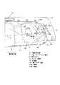
図1は本発明を採用した第一実施形態の内装構造の概略側面図、図2は三列目シート側方のトリム類を外して示した車室内の側面図、図3は図2のA−A線矢視断面図、図4は図2のB−B線矢視断面図である。
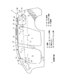
図1に示すように、この第一実施形態を採用した車両Vは、車室内に車両前後方向に三人の乗員P(頭部のみ一点鎖線で示す)が着座できるように、三列のシート(図示せず)を備えたワゴンタイプの車両である。そして、この車両Vの車体側壁には、前方側から三角窓開口1、フロントドア開口2、リアドア開口3、クォーターウィンド開口4がそれぞれ形成されている。
Hereinafter, embodiments of the present invention will be described in detail with reference to the drawings.
FIG. 1 is a schematic side view of the interior structure of the first embodiment employing the present invention, FIG. 2 is a side view of the interior of the vehicle interior with the trims on the side of the third row seats removed, and FIG. FIG. 4 is a cross-sectional view taken along line A-A, and FIG. 4 is a cross-sectional view taken along line B-B in FIG.
As shown in FIG. 1, the vehicle V employing the first embodiment has three rows of seats so that three passengers P (only the head is indicated by a one-dot chain line) can be seated in the vehicle front-rear direction. It is a wagon type vehicle equipped with (not shown). A triangular window opening 1, a front door opening 2, a rear door opening 3, and a
また、三角窓開口1の前方には、車両後方側斜め上方に延びる第一ピラー5を設けており、三角角開口1の後方には、同様に斜め上方に延びる第二ピラー6を設けている。
In addition, a
そして、フロントドア開口2の後方には、上下方向に延びる第三ピラー7を設けており、リアドア開口3の後方には、上下方向に延びる第四ピラー8を設けており、さらに、クォーターウィンド開口4の後方には、上下方向に延びる第五ピラー9を設けている。
A
そして、フロントドア開口2と、リアドア開口3と、クォーターウィンド開口4の上方には、車両前後方向に延びるルーフサイドレール部10を設けている。
A roof
このルーフサイドレール部10には、各開口2,3,4の上縁部に沿って、車両前後方向に延びる収納状態のカーテン部材11を設置している。このカーテン部材11は、車体側部材であるルーフサイドレール部10に、複数の取付けフランジ12…を介して締結固定されており、車体に強固に固定されている。
このカーテン部材11は、周知のように、布製の袋状のエアバッグ体で構成しており、膨張部と非膨張部とを備えており、このうち膨張部にガスを供給することで、車室内でカーテン状に大きく展開膨張するように構成している(図1では破線で展開状態を示す)。
The roof
As is well known, the
また、このカーテン部材11は、図1に示すように、展開時にはフロントドア開口2の上部とリアドア開口3の上部とクォーターウィンド開口4を覆うように展開して、乗員の頭部P等に作用する側突荷重等の衝撃を緩和するようにしている。
Further, as shown in FIG. 1, the
なお、カーテン部材11は収納状態では、所定の折り畳み構造で折り畳まれているが、この折り畳み構造は、後述するカーテン部材11の作動挙動を考慮すると「蛇腹折り」が望ましい。もっとも、後述する作動挙動が達成できれば、「ロール折り」であってもよい。
The
カーテン部材11の中央上方位置には、側突時等にガスを発生して、カーテン部材11の膨張部にガスを供給するインフレータ13を設けている。このインフレータ13は、長尺状の円筒部材によって構成しており、カーテン部材11同様、車両前後方向に延びるように配置している。そして、側突時等には、作動信号を受けることで、カーテン部材11に供給するガスを発生するように構成している。
An
また、カーテン部材11の第二ピラー側(車両前方側側端部)11Aには、紐状の第一テザー部材14を設け、カーテン部材11の側端部(11A)と第二ピラー6の中間部とを連結固定している。この第一テザー部材14を設けることで、カーテン部材11の展開時には、カーテン部材11の第二ピラー側11Aにテンション(張力)を発生させることができる。
In addition, a string-like
一方、カーテン部材11の第五ピラー側(車両後方側側端部)11Bにも、紐状の第二テザー部材15を設けて、カーテン部材11と第五ピラー9とを連結固定している。この第二テザー部材15を設けることによっても、カーテン部材11の展開時には、カーテン部材11の第五ピラー側11Bにテンション(張力)を発生させることができる。
On the other hand, a string-like
もっとも、この第二テザー部材15は、カーテン部材11の外側端部11Cに固定されるのではなく、やや中央側に固定されている。これは、収納状態のカーテン部材11の第五ピラー側11Bに、折曲部16を設けているからである。
However, the
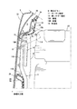
そこで、この折曲部と第二テザー部材の詳細構造について、図2、図3、図4で説明する。 Therefore, the detailed structure of the bent portion and the second tether member will be described with reference to FIGS.
まず、折曲部16は、図2に示すように、収納状態のカーテン部材11の第五ピラー側11Bに設定されており、カーテン部材11の本体部11Dの車室内側で、車両前方側(反第五ピラー側)に折り返されるように形成される。
First, as shown in FIG. 2, the
具体的には、折曲部16がクォーターウィンド開口4の上縁に沿うように折り返され、その前後長さL1が、クォーターウィンド開口4の前後長さL2よりも、短くなるように形成されている。
Specifically, the
また、この折曲部16は、ルーフサイドレール部10に締結固定される保持ブラケット17によって保持される。具体的には、図4に示すように、下側を開放した受け部17aを備える断面柄杓形状の保持ブラケット17に対して、カーテン部材11の本体部11Dと共に並んで保持される。
The
この折曲部16が保持されるルーフサイドレール部10は、アウターサイドパネル21とインナーサイドパネル22とによって、車両前後方向に延びる閉断面Wを構成しており、内部には、剛性を高めるためにレインフォースメント23を設けている。
The roof
また、ルーフサイドレール部10の内端フランジ10aには、ルーフパネル24の外端フランジ24aを接合しており、さらに、ルーフサイドレール部10の外端フランジ10bには、シール部材25を介して、クォーターウィンドガラス26を支持している。なお、ルーフパネル24の下方には、車幅方向に延びるルーフクロスレイン27を設けている。
Further, the
こうしたカーテン部材11と保持ブラケット17は、ルーフサイドレール部10の下方で、車室天井を構成するルーフトリムRによって覆われている。このルーフトリムRは、軟質の発泡ウレタン部材又は軟質の樹脂部材によって成形しており、外部荷重を受けた際には、容易に変形するように構成している。
The
このため、カーテン部材11が展開膨張して際には、図示するようにルーフトリムRの側部Raが下方に変形して(Ra′)、口開き状態で変形する。よって、カーテン部材11の展開動作を阻害するおそれがなく、カーテンエアバッグ装置の安全機能を高めることができる。
For this reason, when the
さらに、カーテン部材11が展開膨張する際には、後述のように縫合ライン部40(図6参照)を設けているため、二点鎖線で示すように、本体部11Dのみが、初めに下方(クォーターウィンド開口4側)に移動して、後から折曲部16が展開膨張していくことになる。
Furthermore, when the
このため、ルーフトリムRの変形量(口開き量)が少なくても、カーテン部材11を確実に車室内方側に展開させることができる。
For this reason, even if the deformation amount (opening amount) of the roof trim R is small, the
また、図3に示すように、カーテン部材11は、平面視で折曲部16が設定されている部分で、本体部11Dが、やや車幅方向外方側に屈曲して配置されるように設置している。
Further, as shown in FIG. 3, the
このように、本体部11Dを配置することで、折曲部16を折り返して本体部11Dの側方に配置しても、車室内方側への突出量を低減することができるため、三列目シートS3に着座する乗員に圧迫感を与えることがない。
In this way, by arranging the
また、本体部11Dは、折曲部16が設定されていない部分では、車幅方向内方側に位置するように設置している。このため、本体部11Dの外方側に、第四ピラー8のインナパネル8aを配置することができる。なお、28は、第四ピラー8の車室内方を覆うCピラートリムである。
Further, the
一方、第二テザー部材15は、図2に示すように、長帯状の布製部材で構成している。そして、その後端15Aを第五ピラー9の上下方向中間部より下側所定位置Q(第五ピラー9上端からの距離eが約100mm以上離間した位置)に、固定ピン30で固定して、その前端15Bをカーテン部材11の本体部11Dに縫合部31で固定している。
On the other hand, as shown in FIG. 2, the
具体的には、図3に示すように、前端15Bは、カーテン部材11の本体部11Dの車外側、より詳細には、本体部11Dの折曲げ位置の境界11Eの近傍に、縫合部31を介して強固に縫合固定されている。一方、後端15Aは、第五ピラー9の前側壁9aに、固定ピン30を介して強固にピン結合されている。
Specifically, as shown in FIG. 3, the
また、第二テザー部材15は、第五ピラー9と第五ピラーを覆うDピラートリム29との間の隙間S(約1〜3mm)を、挿通させることで第五ピラー9とカーテン部材11を連結している。
The
このDピラートリム29は、硬質の合成樹脂によって成形している。このように、Dピラートリム29を硬質の合成樹脂で成形することで、荷物等によって押圧された場合でも、Dピラートリム29が容易に変形するのを抑えている。 The D pillar trim 29 is formed of a hard synthetic resin. As described above, the D pillar trim 29 is formed of a hard synthetic resin, so that the D pillar trim 29 is prevented from being easily deformed even when pressed by a load or the like.
もっとも、Dピラートリム29は、カーテン部材11が展開する際に、Dピラートリム29が変形しなくても、第二テザー部材15が自由に移動できるように、係止固定が容易に解除されるクリップ部材32で、第五ピラー9に係合固定されている。
However, the D-
この第五ピラー9は、アウターパネル33とインナパネル34とで、上下方向に延びる閉断面Xを構成しており、内部にレインフォースメント35を設けることで、閉断面Xの剛性を高めている。このうち、インナパネル34に対して、第二テザー部材15やDピラートリム29を固定している。
In the
なお、一点鎖線で示す断面Rは、ルーフトリムであり、このルーフトリムRによって、収納状態のカーテン部材11は、覆われることになる。
In addition, the cross section R shown with a dashed-dotted line is a roof trim, and the
もっとも、この折曲部16は、この実施形態のように、完全に車両前方側に折り曲げるだけでなく、例えば、二点差線で示すもの116のように、平面視でルーフトリムRの側縁近傍に略沿って折り曲げられるものであれば良く、例えば、この折曲がり角度αは、50°〜180°に設定することが考えられる。
However, the
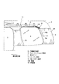
次に、図5、図6を利用して、この実施形態におけるカーテンエアバッグ装置の作動挙動について説明する。図5はカーテン部材の収納状態を示した側面図、図6はカーテン部材の展開状態を示した側面図である。なお、いずれの図においても、カーテン部材11の状態が分かり易いように、ルーフトリムRを仮想の一点鎖線で示している。
Next, the operation behavior of the curtain airbag device in this embodiment will be described with reference to FIGS. FIG. 5 is a side view showing a stored state of the curtain member, and FIG. 6 is a side view showing a developed state of the curtain member. In any of the drawings, the roof trim R is indicated by a virtual one-dot chain line so that the state of the
まず、図5に示すように、カーテン部材11は、通常時には、収納状態でリアドア開口3とクォーターウィンド開口4の上縁部に沿って、車両前後方向に延びるように設置されている。なお、この状態では、カーテン部材11は、ルーフトリムRに覆われている。
First, as shown in FIG. 5, the
また、第二テザー部材15は、後端15Aが第五ピラー9の下側所定位置Qに固定されて、後半部15Cが第五ピラー9とDピラートリム29との間に位置するように設置されている。また、第二テザー部材15の前半部15Eも、第五ピラー9とルーフトリムRの間に位置するように設置されている。
The
こうして、カーテン部材11も第二テザー部材15も、通常時には、ルーフトリムRとDピラートリム29で覆われており、車室内には、露出していない。
Thus, both the
図6に示すように、側突等が生じて、車両に側突荷重が作用した場合には、図示しない衝突センサ及び制御ユニットによって、インフレータ13に作動信号が送信されて、インフレータ13がガスを発生する。そして、このガスをカーテン部材11に供給することで、カーテン部材11が展開膨張する。
As shown in FIG. 6, when a side collision or the like occurs and a side collision load acts on the vehicle, an operation signal is transmitted to the inflator 13 by a collision sensor and control unit (not shown), and the inflator 13 generates gas. appear. Then, by supplying this gas to the
このとき、ガスは、矢印で示すように、車両後方側に向かって流れる。このため、カーテン部材11は、インフレータ13近傍から車両後方側に向かって膨らむと共に、リアドア開口3とクォーターウィンド開口4を覆うように下方側に向かって展開することになる。
At this time, the gas flows toward the rear side of the vehicle as indicated by an arrow. For this reason, the
もっとも、カーテン部材11には、上下方向中央位置に、側面視で略「逆くの字」状に縫合した縫合ライン部40を設けている。このため、カーテン部材11の折曲部に相当する部分16´(二点鎖線ラインTより後方側部分)には、一気にガスが流れることがなく、縫合ライン部40の上側と下側を経由してガスが流れ込むことになる。
However, the
よって、この折曲部に相当する部分16´については、本体部11Dよりやや遅れて展開膨張することになり、前述したように、ルーフトリムRの変形量が少なくても、カーテン部材11を確実に車室内方側に展開させることができる。
Therefore, the
なお、この縫合ライン部40は、折曲げ位置の境界11Eを外した本体部11D側に形成している。これは、折曲げ位置の境界11Eに縫合ライン部40に形成すると、縫合ライン部40でカーテン部材11の剛性が高まり、折り返すことが困難になるからである。
The
また、カーテン部材11が展開膨張すると、第二テザー部材15もカーテン部材11に引っ張られて車室内に露出する。このとき、第二テザー部材15は、前端15Bがカーテン部材11の本体部11Dに縫合固定されているため、カーテン部材11の展開位置を拘束して、張力(テンション)が発生することになる。
Further, when the
こうして、第二テザー部材15によって、カーテン部材11と第五ピラー9との間で、テンションを発生させることで、カーテン部材11に車両前後方向に延びる「テンションライン」TLを形成することができる。
Thus, by generating tension between the
そして、このテンションラインTLは、第二テザー部材15の第五ピラー9への固定位置を後端TL1として、第一テザー部材14の第二ピラー6への固定位置を前端TL2として(図1参照)、車両前後方向に延びるように形成されることになる。
The tension line TL has a position where the
そして、このテンションラインTLは、三列目シートに着座した乗員Pの頭部重心POよりも下方位置に設定される。このため、車両がロールオーバーした際には、乗員Pを保護することができる。 The tension line TL is set at a position below the head center of gravity PO of the occupant P seated on the third row seat. For this reason, when the vehicle rolls over, the occupant P can be protected.
また、折曲部16がDピラートリム29側に展開することで、Dピラートリム29から露出する第二テザー部材15も、折曲部に相当する部分16´で覆うことができ、第二テザー部材15が乗員Pに直接接触することもない。
さらに、第二テザー部材15が折曲部に相当する部分16′の外方側にあることによって、乗員Pがカーテン部材11に接触した場合にも、カーテン部材11の展開位置が拘束されて、カーテン部材11が車外側に移動するのを防止できる。
In addition, the
Furthermore, since the
このように、第二テザー部材15と折曲部16があることによって、カーテン部材11が展開膨張した際のカーテンエアバッグ装置の安全性を高めることができるのである。
Thus, the presence of the
次に、このように構成した本実施形態の作用効果について説明する。
この実施形態では、側突時等においてクォーターウィンド開口4等の車室内方側に展開膨張するカーテン部材11を有するカーテンエアバッグ装置を有しており、このカーテン部材11の第五ピラー9側には、収納状態で折り返される折曲部16を設定して、このカーテン部材11の本体部11Dと第五ピラー9の下側固定位置Qとの間には、両者を連結する第二テザー部材15を設けている。
Next, the effect of this embodiment comprised in this way is demonstrated.
In this embodiment, the curtain airbag device having the
これにより、側突時等にカーテン部材11が展開膨張した際には、第二テザー部材15が、カーテン部材11の本体部11Dと第五ピラー9の下側所定位置Qの間で、張力を発生することになる。
このため、第二テザー部材15によって、テンションを生じさせることができ、カーテン部材11に、車両前後方向に延びるテンションラインTLを設定することができる。
よって、カーテンエアバッグを備えた車両の内装構造において、ルーフトリムR内にカーテン部材11をその先端部(16)を折り曲げて収納するものであって、展開時に、車両前後方向に延びるテンションラインTLをカーテン部材11に設定することができ、カーテン部材11でクォーターウィンド開口4等を覆った状態を維持することができる。
Thereby, when the
For this reason, tension can be generated by the
Therefore, in the interior structure of a vehicle equipped with a curtain airbag, the
また、この実施形態では、第二テザー部材15の結合されるカーテン部材11の部位が、カーテン部材11の展開状態で折曲げ位置の境界11Eよりも本体部11D側(反第五ピラー側)に設定されている。
これにより、カーテン部材11が展開膨張する際に、折曲部16よりも早期に展開する本体部11Dに、第二テザー部材15が連結されることになる。
このため、第二テザー部材15が速く移動し始めることになり、第二テザー部材15が早期且つ確実に張力を発生できる。
よって、第二テザー部材15の張力発生機能を、より早く且つ確実に得ることができる。
Further, in this embodiment, the portion of the
Thereby, when the
For this reason, the
Therefore, the tension generating function of the
また、この実施形態では、第二テザー部材15の結合されるカーテン部材11の部位が、本体部11Dの折曲げ位置の境界11Eの近傍に設定されている。
これにより、カーテン部材11の第五ピラー9に最も近い部分に、第二テザー部材15を結合することになる。
よって、第二テザー部材15の長さを短くすることができるため、カーテン部材11の展開時に、第二テザー部材15に引っ掛かるのを防止でき、また、第二テザー部材15の張力も容易に発生させることができる。
In this embodiment, the portion of the
As a result, the
Therefore, since the length of the
また、この実施形態では、第二テザー部材15が、カーテン部材11の展開時に、このカーテン部材11より車体外方側に位置するように設定されている。
これにより、カーテン部材11の展開時に、第二テザー部材15が乗員Pに直接接触することがない。また、折曲部16が展開した際に第二テザー部材15によって車外側へ移動するのを抑えることができる。
よって、カーテン部材11展開時の乗員Pの違和感を軽減して、カーテン部材11の車室内での完全な展開状態を維持することができる。
In this embodiment, the
Thereby, the
Therefore, it is possible to reduce the uncomfortable feeling of the occupant P when the
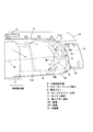
次に、この発明の第二実施形態について、図7を利用して説明する。この図7は、第二実施形態のカーテン部材の展開状態を示した側面図である。なお、第一実施形態と同様の構成要素については、同一の符号を付して説明を省略する。 Next, a second embodiment of the present invention will be described with reference to FIG. This FIG. 7 is the side view which showed the expansion | deployment state of the curtain member of 2nd embodiment. In addition, about the component similar to 1st embodiment, the same code | symbol is attached | subjected and description is abbreviate | omitted.
この実施形態では、第二テザー部材115の第五ピラー9への固定位置とカーテン部材11への縫合位置を、第一実施形態のもの(二点鎖線で示す15)より、やや上方に設定することで、カーテン部材11の展開時に、第二テザー部材115が略水平状態で延びるようにしている。
In this embodiment, the fixing position of the
具体的には、第二テザー部材115の後端115Aを第五ピラー9の上下方向略中間位置に固定して、第二テザー部材115の前端115Bをカーテン部材11の本体部11Dの上下方向略中間位置に縫合固定する。すなわち、第二テザー部材の前端115Bと第二テザー部材の後端115Aの固定位置を、それぞれ略同じ高さとなるように設定しているのである。
Specifically, the
このように、第二テザー部材の前端115Bと後端115Aを、第五ピラー9とカーテン部材11の略同じ高さ位置に固定することにより、図示するように、第二テザー部材115が略水平方向に延びる。このため、第二テザー部材115は、テンションラインTLに略一致して延びることになり、テンションラインTLでのカーテン部材11の支持剛性をさらに高めることができる。
Thus, by fixing the
また、このように、第二テザー部材115の固定位置を設定することで、第一実施形態のもの15よりも、第二テザー部材115の長さをさらに短くすることができる。
すなわち、カーテン部材11の展開時に、第二テザー部材の前端115Bを、カーテン部材11の上下方向略中間位置に位置させるためには、第二テザー部材115の全長が短くなければならないため、必然的に第二テザー部材115を短く構成できるのである。
In addition, by setting the fixing position of the
That is, in order to position the
こうして、第二テザー部材115が短いことにより、カーテン部材11の展開時に、第二テザー部材115がカーテン部材11に引っ掛かることも防止でき、より安全性の高いカーテンエアバッグ装置にすることができる。
Thus, since the
このように、この実施形態では、第二テザー部材115の結合されるカーテン部材11の部位(115B)を、カーテン部材11の展開状態で、第五ピラー9に連結された位置(115A)と略同じ高さとなるように設定している。
これにより、第二テザー部材115が、カーテン部材11の展開時に、略水平方向に延びた状態で、張力を発生することになる。また、第二テザー部材115の長さも、より短くすることができる。
よって、カーテン部材11に発生するテンションラインTLの張力をより確実に高めることができ、また、第二テザー部材115をより短く構成して、カーテン部材11の展開時の引っ掛かりを防止することができる。
Thus, in this embodiment, the part (115B) of the
Thereby, the tension | tensile_strength is generated in the state which the
Therefore, the tension of the tension line TL generated in the
また、この第二実施形態では、図示するように、カーテン部材11の中央位置に大きな非膨張部101を設けている。このような大きな非膨張部101を設けることで、インフレータ13から供給するガスが少なくても、カーテン部材11を早期且つ確実に展開させることができる。
Moreover, in this 2nd embodiment, the big
なお、この非膨張部101は、乗員Pの頭部が位置しない部分に設けることで、乗員Pの保護を図りつつ、カーテン部材11の早期の展開を可能にすることができる。
In addition, by providing the
以上、この発明の構成と前述の実施形態との対応において、
この発明のピラートリムは、実施形態のDピラートリム29に対応して、
以下、同様に、
車体開口部は、クォーターウィンド開口4に対応し、
連結部材は、第二テザー部材15,115に対応するも、
この発明は、前述の実施形態に限定されるものではなく、あらゆるカーテンエアバッグを備えた車両の内装構造に適用する実施形態を含むものである。
これらの実施形態では、第二テザー部材15,115を帯状の部材で構成したが、例えば、三角巾状の部材で構成しても良いし、また、糸状の部材で構成しても良い。さらには、カーテン部材と一体の布状部で構成しても良い。
また、これらの実施形態では、車両後端の車体ピラーとカーテン部材を連結した連結部材で説明したが、この発明はこれに限定されるものではなく、車両前端の車体ピラーとカーテン部材を連結する連結部材で実施してもよい。
As described above, in the correspondence between the configuration of the present invention and the above-described embodiment,
The pillar trim of the present invention corresponds to the D pillar trim 29 of the embodiment,
Similarly,
The vehicle body opening corresponds to the
The connecting member corresponds to the
The present invention is not limited to the above-described embodiment, but includes an embodiment applied to an interior structure of a vehicle including any curtain airbag.
In these embodiments, the
In these embodiments, the connecting member that connects the vehicle body pillar and the curtain member at the rear end of the vehicle has been described. However, the present invention is not limited to this, and connects the vehicle body pillar and the curtain member at the front end of the vehicle. You may implement with a connection member.
V…車両
Q…下側所定位置
4…クォーターウィンド開口
9…第五ピラー
10…ルーフサイドレール部
11…カーテン部材
15…第二テザー部材
15A…後端
15B…前端
16…折曲部
115…第二テザー部材
115A…後端
115B…前端
V ... Vehicle Q ... Lower
Claims (5)
合成樹脂によって成形されて車体ピラーを車室内方側から覆う上下方向に延びるピラートリムと、
前記車体ピラーに隣接して、上縁がルーフトリムの外端部近傍に位置する車体開口部と、
該車体開口部の上縁近傍に沿うように車体に固定されて、カーテン状でガスが供給可能な膨張部が形成されており、収納状態から所定条件で膨張部にガスが供給されることで、前記ルーフトリムを変形させて車室内に広がり、前記車体開口部を覆うように展開するカーテン部材を有するカーテンエアバッグ手段とを備え、
前記カーテン部材には、収納状態で前記車体ピラーの近傍に、折曲げ位置を境界として該車体ピラーの反対側に折り曲げられる折曲部を設定しており、
該カーテン部材の所定部位と、前記車体ピラーの上下方向中間部より下側所定位置とを連結する連結部材を有する
カーテンエアバッグを備えた車両の内装構造。 A roof trim that forms a ceiling in the passenger compartment below the roof panel;
Pillar trim that is molded of synthetic resin and extends in the vertical direction to cover the vehicle body pillar from the vehicle interior side;
A vehicle body opening adjacent to the vehicle body pillar and having an upper edge located near the outer end of the roof trim;
An inflatable portion that is fixed to the vehicle body along the vicinity of the upper edge of the vehicle body opening and is capable of supplying gas in the form of a curtain is formed, and gas is supplied to the inflatable portion under predetermined conditions from the housed state. A curtain airbag means having a curtain member that deforms the roof trim to expand into the vehicle interior and covers the vehicle body opening,
The curtain member has a bent portion that is bent to the opposite side of the vehicle body pillar with the folding position as a boundary in the vicinity of the vehicle body pillar in the housed state.
An interior structure of a vehicle including a curtain airbag having a connecting member that connects a predetermined portion of the curtain member and a predetermined position below an intermediate portion in the vertical direction of the vehicle body pillar.
請求項1記載のカーテンエアバッグを備えた車両の内装構造。 The interior of a vehicle with a curtain airbag according to claim 1, wherein a predetermined portion of the curtain member to which the connecting member is coupled is set on the side opposite to the vehicle body pillar from the boundary of the folding position in the deployed state of the curtain member. Construction.
請求項2記載のカーテンエアバッグを備えた車両の内装構造。 The interior structure of a vehicle including a curtain airbag according to claim 2, wherein a predetermined portion of the curtain member is set in the vicinity of a boundary of the folding position.
請求項1記載のカーテンエアバッグを備えた車両の内装構造。 The interior of a vehicle provided with a curtain airbag according to claim 1, wherein the predetermined part of the curtain member is set to be substantially the same height as a predetermined position where the connecting member is connected to the vehicle body pillar in the deployed state of the curtain member. Construction.
請求項1記載のカーテンエアバッグを備えた車両の内装構造。
The interior structure of a vehicle provided with a curtain airbag according to claim 1, wherein the connecting member is set so as to be positioned on the outer side of the vehicle body from the curtain member when the curtain member is deployed.
Priority Applications (3)
| Application Number | Priority Date | Filing Date | Title |
|---|---|---|---|
| JP2008205046A JP5169606B2 (en) | 2008-08-08 | 2008-08-08 | Interior structure of vehicle with curtain airbag |
| US12/480,178 US8033569B2 (en) | 2008-08-08 | 2009-06-08 | Interior structure of vehicle equipped with curtain airbag |
| EP09009755A EP2151360B1 (en) | 2008-08-08 | 2009-07-28 | An interior structure of a vehicle equipped with a curtain airbag and method of providing it |
Applications Claiming Priority (1)
| Application Number | Priority Date | Filing Date | Title |
|---|---|---|---|
| JP2008205046A JP5169606B2 (en) | 2008-08-08 | 2008-08-08 | Interior structure of vehicle with curtain airbag |
Publications (2)
| Publication Number | Publication Date |
|---|---|
| JP2010036831A true JP2010036831A (en) | 2010-02-18 |
| JP5169606B2 JP5169606B2 (en) | 2013-03-27 |
Family
ID=42009807
Family Applications (1)
| Application Number | Title | Priority Date | Filing Date |
|---|---|---|---|
| JP2008205046A Expired - Fee Related JP5169606B2 (en) | 2008-08-08 | 2008-08-08 | Interior structure of vehicle with curtain airbag |
Country Status (1)
| Country | Link |
|---|---|
| JP (1) | JP5169606B2 (en) |
Cited By (1)
| Publication number | Priority date | Publication date | Assignee | Title |
|---|---|---|---|---|
| JP2011213194A (en) * | 2010-03-31 | 2011-10-27 | Mazda Motor Corp | Interior structure of vehicle |
Citations (3)
| Publication number | Priority date | Publication date | Assignee | Title |
|---|---|---|---|---|
| JP2003104162A (en) * | 2001-09-27 | 2003-04-09 | Toyoda Gosei Co Ltd | Head protecting airbag system |
| JP2006151390A (en) * | 2006-03-13 | 2006-06-15 | Mazda Motor Corp | Vehicle occupant protection device |
| JP2007055545A (en) * | 2005-08-26 | 2007-03-08 | Toyota Motor Corp | Airbag device for head protection |
-
2008
- 2008-08-08 JP JP2008205046A patent/JP5169606B2/en not_active Expired - Fee Related
Patent Citations (3)
| Publication number | Priority date | Publication date | Assignee | Title |
|---|---|---|---|---|
| JP2003104162A (en) * | 2001-09-27 | 2003-04-09 | Toyoda Gosei Co Ltd | Head protecting airbag system |
| JP2007055545A (en) * | 2005-08-26 | 2007-03-08 | Toyota Motor Corp | Airbag device for head protection |
| JP2006151390A (en) * | 2006-03-13 | 2006-06-15 | Mazda Motor Corp | Vehicle occupant protection device |
Cited By (1)
| Publication number | Priority date | Publication date | Assignee | Title |
|---|---|---|---|---|
| JP2011213194A (en) * | 2010-03-31 | 2011-10-27 | Mazda Motor Corp | Interior structure of vehicle |
Also Published As
| Publication number | Publication date |
|---|---|
| JP5169606B2 (en) | 2013-03-27 |
Similar Documents
| Publication | Publication Date | Title |
|---|---|---|
| US9027954B2 (en) | Airbag device | |
| JP6386361B2 (en) | Roof head lining structure that houses curtain airbags for vehicles | |
| JP2007190988A (en) | Seat device | |
| JP6848839B2 (en) | Vehicle curtain airbag device | |
| JP2008137458A (en) | Airbag device | |
| WO2009144971A1 (en) | Head-restraining airbag system | |
| JP2011240884A (en) | Curtain airbag device | |
| JP2010006100A (en) | Interior trim structure of vehicle | |
| JP2008114739A (en) | Vehicle rear structure provided with curtain airbag device | |
| JP4631778B2 (en) | Airbag device | |
| JP4476952B2 (en) | Vehicle occupant protection device | |
| JP6872373B2 (en) | Airbag | |
| JP5015851B2 (en) | Vehicle occupant protection device | |
| JP5169606B2 (en) | Interior structure of vehicle with curtain airbag | |
| JP2008024129A (en) | Vehicle provided with curtain airbag device | |
| JP5169613B2 (en) | Interior structure of vehicle with curtain airbag | |
| JP5034552B2 (en) | Rear structure of vehicle with curtain airbag device | |
| JP4272416B2 (en) | Side curtain airbag gas flow path structure | |
| JP2010047035A (en) | Interior structure for vehicle provided with curtain airbag | |
| JP2010069968A (en) | Interior structure of vehicle equipped with curtain airbag | |
| JP6090055B2 (en) | Side airbag device | |
| JP2002370605A (en) | Head part protecting air bag device | |
| JP5163399B2 (en) | Interior structure of vehicle with curtain airbag | |
| JP5634186B2 (en) | Airbag device | |
| JP5092448B2 (en) | Rear structure of vehicle with curtain airbag device |
Legal Events
| Date | Code | Title | Description |
|---|---|---|---|
| A621 | Written request for application examination |
Free format text: JAPANESE INTERMEDIATE CODE: A621 Effective date: 20110620 |
|
| A521 | Written amendment |
Free format text: JAPANESE INTERMEDIATE CODE: A523 Effective date: 20120329 |
|
| A977 | Report on retrieval |
Free format text: JAPANESE INTERMEDIATE CODE: A971007 Effective date: 20120719 |
|
| A131 | Notification of reasons for refusal |
Free format text: JAPANESE INTERMEDIATE CODE: A131 Effective date: 20120724 |
|
| A521 | Written amendment |
Free format text: JAPANESE INTERMEDIATE CODE: A523 Effective date: 20120921 |
|
| TRDD | Decision of grant or rejection written | ||
| A01 | Written decision to grant a patent or to grant a registration (utility model) |
Free format text: JAPANESE INTERMEDIATE CODE: A01 Effective date: 20121204 |
|
| A61 | First payment of annual fees (during grant procedure) |
Free format text: JAPANESE INTERMEDIATE CODE: A61 Effective date: 20121217 |
|
| R150 | Certificate of patent or registration of utility model |
Ref document number: 5169606 Country of ref document: JP Free format text: JAPANESE INTERMEDIATE CODE: R150 |
|
| LAPS | Cancellation because of no payment of annual fees |