JP2010006100A - Interior trim structure of vehicle - Google Patents
Interior trim structure of vehicle Download PDFInfo
- Publication number
- JP2010006100A JP2010006100A JP2008164133A JP2008164133A JP2010006100A JP 2010006100 A JP2010006100 A JP 2010006100A JP 2008164133 A JP2008164133 A JP 2008164133A JP 2008164133 A JP2008164133 A JP 2008164133A JP 2010006100 A JP2010006100 A JP 2010006100A
- Authority
- JP
- Japan
- Prior art keywords
- pillar
- vehicle
- trim
- curtain member
- curtain
- Prior art date
- Legal status (The legal status is an assumption and is not a legal conclusion. Google has not performed a legal analysis and makes no representation as to the accuracy of the status listed.)
- Granted
Links
Images


Abstract
Description
この発明は、ピラーの車室内側を覆うピラートリムと、ピラーの上端部より前後方向他方側に配設されるルーフサイドレールと、該ルーフサイドレールより下方に広がる車体の開口部を覆うようにカーテン部材が展開するエアバッグ手段とを備えた車両の内装構造に関する。 The present invention provides a pillar trim that covers a vehicle interior side of a pillar, a roof side rail that is disposed on the other side in the front-rear direction from the upper end of the pillar, and a curtain that covers an opening of a vehicle body that extends downward from the roof side rail. The present invention relates to an interior structure of a vehicle including airbag means for deploying members.
車体の開口部(ウインド部)の縁にカーテン部材を収容しておき、車両衝突検出時や衝突予知時に上記カーテン部材にガスを供給することにより、これを膨張展開させて開口部を瞬時に覆うようにしたカーテンエアバッグ装置は一般に知られている。 A curtain member is accommodated at the edge of the opening (window) of the vehicle body, and gas is supplied to the curtain member when a vehicle collision is detected or when a collision is predicted. Such a curtain airbag device is generally known.
この装置の場合、そのカーテン部材に張力が得られないと、乗員を十分に保護することができない。そこで、カーテン部材の車両前後方向一方側端部を車両のピラーに連結する連結部を備え、カーテン部材の膨張展開時に上記開口部を横切るようにして上記連結部を車両前後方向に張らせることで、展開状態にあるカーテン部材の所定の高さ位置にテンションラインを形成するようにしたものが提案されている(特許文献1参照)。 In the case of this device, the occupant cannot be sufficiently protected unless tension is obtained in the curtain member. Therefore, a connecting portion for connecting one end of the curtain member in the vehicle front-rear direction to the vehicle pillar is provided, and the connecting portion is stretched in the vehicle front-rear direction so as to cross the opening when the curtain member is inflated and deployed. There has been proposed one in which a tension line is formed at a predetermined height position of a curtain member in an unfolded state (see Patent Document 1).
この場合、車両衝突時等で衝撃を受けた時には、前後方向に十分な張力が作用しているカーテン部材によって、乗員が車室内に留まるように保護することが可能になり、これにより乗員保護性能を向上することができる。
ところで、近年、車両のデザインの多様化等により、例えば図6、図7に示す車両Vのように、開口部(サイドウインド)101の車両前側において、前端側のAピラー104と、該Aピラー104の後側のサブピラー105とにより大型の三角窓109が形成される場合があり、このような車両に対しても、上述したようなカーテンエアバッグ装置110を備えることが考えられている。なお、図6は、車両の内装構造を構成するカーテンエアバッグ装置(乗員保護装置)をカーテン部材の収納状態において車室内側から見た正面図であり、図7は、図6に示すカーテンエアバッグ装置をカーテン部材の展開状態において車室内側から見た正面図である。なお、図中において矢印(F)は車両前方、矢印(R)は車両後方を示す。
By the way, due to diversification of vehicle designs in recent years, the
図6、図7に示す車両Vでは、三角窓109が、座席S1〜S3の乗員Cの頭部の高さ位置近くまで延びる程大型なものとなっており、これによりピラー104、105は長尺なものとなっている。
In the vehicle V shown in FIGS. 6 and 7, the
ここで、ピラーは、一般的に車室内側からピラートリムにより覆われており、ピラー104、105では、ピラートリム123は、見映え向上の観点から、図8に示すように、各ピラー104、105に対応する部位123a、123bが一体成形されている。
Here, the pillar is generally covered with a pillar trim from the vehicle interior side. In the
このため、図8に示すものでは、三角窓109の大型化に伴って長尺に形成されたピラー104、105に対応する必要性も含めて、ピラートリム123が大型化している。なお、図8は、図6に示すAピラー、サブピラー周辺部位を車室前方かつ上方から見た斜視図である。なお、図中において矢印(IN)は車両内方、矢印(OUT)は車両外方を示す。
For this reason, in the structure shown in FIG. 8, the
ここで、このような構成をなすものに対し、上述したカーテンエアバッグ装置を備える場合を考えてみる。この場合、図6〜図8に示すように、連結部としてのテザー113は、そのカーテン部材111側の端部がカーテン部材111の展開時に一体形成されたピラートリム123に引っ掛かることがないように、Aピラー104ではなく、サブピラー105に固定されるのが好ましい。
Here, let us consider a case in which the above-described curtain airbag device is provided for such a configuration. In this case, as shown in FIG. 6 to FIG. 8, the
さらに、乗員Cの頭部をより確実に保護するためには、一般的に、図7に示すように、カーテン部材111の展開時におけるテザー113のラインが、可及的に下方のベルトライン近傍の位置をとるのが好ましいとされている。このような理由から、テザー113の一端部は、図示のように、サブピラー105の下端部近傍に取付けられるのが理想的であると考えられる。
Furthermore, in order to more reliably protect the head of the occupant C, generally, as shown in FIG. 7, the line of the
しかしながら、テザー113のサブピラー105における取付位置をその下端部近傍に設定すると、特にピラートリム123の下端部がピラー下方に位置する固定部材により固定されている場合、カーテン部材111の展開に伴ってテザー113が車両前後方向に延びる状態に移行する時、ピラートリム123の部位123bがサブピラー105から外れる拍子に、部位123bの上端部が下端部を支点にして車幅方向の車室内側に倒れ込む所謂内倒れ現象が発生する虞がある。
However, when the attachment position of the
そして、このような内倒れ現象が発生すると、カーテン部材111の展開、つまりはテザー113の移動の影響を受けにくい部位123a側はAピラー104での固定状態が保持されているために、部位123a、123bとの間で応力が発生し、ピラートリム123に大きな負荷がかかってクラックや破損等を生じさせることになってしまう。
When such an inward fall phenomenon occurs, the
また、カーテン部材111の膨張展開時においては、ピラートリム123の部位123bがサブピラー105から外れることによって、テザー113のカーテン部材111側端部が、サブピラー105と部位123bとの間から車両後方の開口部101側に移動することになるが、この時、部位123bがサブピラー105から十分に離間していないと、テザー113の移動が妨げられ、カーテン部材111に対し適切に張力を付与することができなくなってしまう。
Further, when the
この発明は、カーテン部材の展開時において、カーテン部材の比較的下側で車両前後方向に張力を作用させることを可能にしつつ、ピラートリムに付与される応力を低減することができる車両の内装構造を提供することを目的とする。 The present invention provides an interior structure of a vehicle capable of reducing stress applied to a pillar trim while allowing tension to be applied in the vehicle front-rear direction at a relatively lower side of the curtain member when the curtain member is deployed. The purpose is to provide.
また、この発明は、カーテン部材の展開時に第2ピラーに対応するピラートリムを適宜移動可能にし、第2ピラーからピラートリムを十分に離間させて連結部を確実に車両前後方向に延びる状態に移行させることができる車両の内装構造を提供することを目的とする。 Further, according to the present invention, when the curtain member is deployed, the pillar trim corresponding to the second pillar can be appropriately moved, and the pillar trim is sufficiently separated from the second pillar so that the connecting portion is shifted to a state of extending in the vehicle front-rear direction. An object of the present invention is to provide an interior structure of a vehicle that can perform the above.
この発明の車両の内装構造は、車体の車両前後方向一方側の第1ピラーと、該第1ピラーの前後方向他方側に配設され、上端部が上記第1ピラーの上端部に近接して位置する第2ピラーと、上記第1ピラーと上記第2ピラーとに固定され、これらピラーの車室内側を覆う一体形成されたピラートリムと、上記第2ピラーの上端部より前後方向の更に他方側に延設するルーフサイドレールと、該ルーフサイドレールに支持され、車両衝突検出/予知時に、上記ルーフサイドレールより下方に広がる車体の開口部を覆うようにカーテン部材が展開するエアバッグ手段とを備えた車両の内装構造であって、上記ピラートリムの上記第2ピラーを覆う部位の下端部は、該第2ピラーの下方に位置するトリム部材に固定支持されるとともに、上記カーテン部材は、展開状態においてベルトライン近傍までその下縁が移動するように展開し、展開状態にある上記カーテン部材の前後方向一方側が、上記第2ピラーの下端部より離間した高さ方向の中間位置に対し、連結部により連結されるものである。 The interior structure of the vehicle according to the present invention includes a first pillar on one side of the vehicle front-rear direction of the vehicle body and the other side of the first pillar in the front-rear direction, and an upper end portion close to the upper end portion of the first pillar. A second pillar that is positioned; a pillar trim that is fixed to the first pillar and the second pillar and covers the interior of the pillar; and the other side in the front-rear direction from the upper end of the second pillar. A roof side rail that extends to the roof side, and an airbag means that is supported by the roof side rail and that deploys a curtain member so as to cover an opening of the vehicle body that extends downward from the roof side rail when a vehicle collision is detected / predicted. The lower end portion of the pillar trim covering the second pillar is fixedly supported by a trim member positioned below the second pillar, and the cart The member is deployed so that its lower edge moves to the vicinity of the belt line in the deployed state, and one side in the front-rear direction of the curtain member in the deployed state is an intermediate position in the height direction separated from the lower end of the second pillar. On the other hand, it is connected by a connecting part.
この構成によれば、展開状態にあるカーテン部材の前後方向一方側が連結部によって第2ピラーの上記中間位置に連結されることで、カーテン部材の比較的下側のベルトライン近傍で車両前後方向に張力を作用させることができ、かつピラートリムの第2ピラーを覆う部位の下端部がトリム部材に固定されることにより生じうる連結部移動時の内倒れ現象を抑制して、ピラートリムに付与される応力を低減することも可能になる。 According to this configuration, one side in the front-rear direction of the curtain member in the unfolded state is connected to the intermediate position of the second pillar by the connecting portion, so that the front-rear direction of the vehicle near the belt line on the lower side of the curtain member. Stress applied to the pillar trim that can be applied with tension and suppresses the internal falling phenomenon at the time of movement of the connecting portion, which can be caused by fixing the lower end portion of the portion covering the second pillar of the pillar trim to the trim member. Can also be reduced.
この発明の一実施態様においては、上記連結部を、帯状または紐状としたものである。 In one embodiment of this invention, the said connection part is made into strip | belt shape or string shape.
この構成によれば、連結部が帯状または紐状をなしていることで、カーテン部材の展開時に上記連結部がピラートリムに与える影響を小さく抑えることができる。 According to this structure, since the connection part is carrying out the strip | belt shape or string shape, the influence which the said connection part has on the pillar trim at the time of expansion | deployment of a curtain member can be restrained small.
この発明の一実施態様においては、上記連結部が、側面視で上記カーテン部材の膨張部の所定部位に連結されることで、該所定部位が膨張しない場合よりも、膨張した場合に上記連結部の張力が大きくなるように構成されるものである。 In one embodiment of the present invention, the connecting portion is connected to a predetermined portion of the inflating portion of the curtain member in a side view so that the connecting portion is expanded when the predetermined portion is not expanded. It is comprised so that tension | tensile_strength may become large.
この構成によれば、カーテン部材の前後方向一方側が連結部により第2ピラーの上記中間位置に連結されるため、連結部を短くすることができるとともに、乗員が着座する側を広く覆うことができる。
さらに、連結部が膨張部の所定部位に連結されることにより、膨張部の所定部位が膨張すると、連結部の車両前後方向の幅を膨張しない場合に比べて短くすることができ、その分カーテン部材の展開時には、上記所定部位が膨張しない場合よりもカーテン部材に対してより大きな張力を作用させることができる。
According to this configuration, since one side in the front-rear direction of the curtain member is connected to the intermediate position of the second pillar by the connecting portion, the connecting portion can be shortened and the side on which the occupant is seated can be widely covered. .
Furthermore, when the connecting portion is connected to the predetermined portion of the inflating portion, when the predetermined portion of the inflating portion is inflated, the width of the connecting portion in the vehicle front-rear direction can be shortened compared to the case where the inflating portion is not inflated. When the member is deployed, a greater tension can be applied to the curtain member than when the predetermined portion does not expand.
この発明の一実施態様においては、上記ピラートリムの内、上記第1ピラーを覆う部位の下端部が上記トリム部材に固定支持されるものである。 In one embodiment of the present invention, a lower end portion of a portion covering the first pillar in the pillar trim is fixedly supported by the trim member.
この構成によれば、ピラートリムの下端部全体が強固に固定されることにより、ピラートリムにはより応力が発生し易い構成となっているが、連結部を第2ピラーの上記中間位置に連結することで、ピラートリムの取付剛性を向上させつつ、ピラートリムにおける応力低減の効果をより顕著なものとすることができる。 According to this structure, since the whole lower end part of the pillar trim is firmly fixed, the pillar trim is configured to generate more stress. However, the connecting part is connected to the intermediate position of the second pillar. Thus, the effect of reducing the stress in the pillar trim can be made more remarkable while improving the mounting rigidity of the pillar trim.
この発明の車両の内装構造は、車体の車両前後方向一方側の第1ピラーと、該第1ピラーの前後方向他方側に配設され、上端部が上記第1ピラーの上端部に近接して位置する第2ピラーと、上記第1ピラーと上記第2ピラーとに固定され、これらピラーの車室内側を覆う一体形成されたピラートリムと、上記第2ピラーの上端部より前後方向の更に他方側に延設するルーフサイドレールと、該ルーフサイドレールに支持され、車両衝突検出/予知時に、上記ルーフサイドレールより下方に広がる車体の開口部を覆うようにカーテン部材が展開するエアバッグ手段とを備えた車両の内装構造であって、上記ピラートリムの上記第2ピラーを覆う部位の下端部は、該第2ピラーの下方に位置するトリム部材に固定支持されるとともに、上記カーテン部材は、上記第2ピラーと連結部により連結されており、収納状態の上記カーテン部材の膨張部が、上記ピラートリムの少なくとも上端部により覆われるように構成されるものである。 The interior structure of the vehicle according to the present invention includes a first pillar on one side of the vehicle front-rear direction of the vehicle body and the other side of the first pillar in the front-rear direction, and an upper end portion close to the upper end portion of the first pillar. A second pillar that is positioned; a pillar trim that is fixed to the first pillar and the second pillar and covers the interior of the pillar; and the other side in the front-rear direction from the upper end of the second pillar. A roof side rail that extends to the roof side, and an airbag means that is supported by the roof side rail and that deploys a curtain member so as to cover an opening of the vehicle body that extends downward from the roof side rail when a vehicle collision is detected / predicted. The lower end portion of the pillar trim covering the second pillar is fixedly supported by a trim member positioned below the second pillar, and the cart Member, the are connected by the second pillar and the connecting portion, the expansion portion of the curtain member in the accommodated state is intended to be configured to be covered by at least the upper end portion of the pillar trim.
この構成によれば、カーテン部材の展開時には、膨張部の膨張による押圧力を利用して、第2ピラーを覆うピラートリムの部位を第2ピラーから外すことが可能になり、第2ピラーから適宜車室内側に離間させることができる。従って、カーテン部材の展開時には、第2ピラーと上記部位との間隔を大きく確保でき、連結部の移動を容易にして、連結部を車両前後方向に延びる状態に確実に移行させることができる。 According to this configuration, when the curtain member is deployed, it is possible to remove the pillar trim portion covering the second pillar from the second pillar by using the pressing force generated by the expansion of the expansion portion. It can be separated indoors. Therefore, when the curtain member is deployed, a large interval between the second pillar and the portion can be secured, the movement of the connecting portion can be facilitated, and the connecting portion can be reliably shifted to a state extending in the vehicle front-rear direction.
この発明によれば、展開状態にあるカーテン部材の前後方向一方側が連結部によって第2ピラーの上記中間位置に連結されることで、カーテン部材の比較的下側のベルトライン近傍で車両前後方向に張力を作用させることができ、かつピラートリムの第2ピラーを覆う部位の下端部がトリム部材に固定されることにより生じうる連結部移動時の内倒れ現象を抑制して、ピラートリムに付与される応力を低減することも可能になる。 According to the present invention, one side of the curtain member in the deployed state in the front-rear direction is connected to the intermediate position of the second pillar by the connecting portion, so that the vehicle member extends in the vehicle front-rear direction near the belt line on the lower side of the curtain member. Stress applied to the pillar trim that can be applied with tension and suppresses the internal falling phenomenon at the time of movement of the connecting portion, which can be caused by fixing the lower end portion of the portion covering the second pillar of the pillar trim to the trim member. Can also be reduced.
また、この発明によれば、カーテン部材の展開時には、膨張部の膨張による押圧力を利用して、第2ピラーを覆うピラートリムの部位を第2ピラーから外すことが可能になり、第2ピラーから適宜車室内側に離間させることができる。従って、カーテン部材の展開時には、第2ピラーと上記部位との間隔を大きく確保でき、連結部の移動を容易にして、連結部を車両前後方向に延びる状態に確実に移行させることができる。 According to the present invention, when the curtain member is deployed, it is possible to remove the pillar trim portion covering the second pillar from the second pillar using the pressing force due to the expansion of the expansion portion. It can be appropriately separated to the vehicle interior side. Therefore, when the curtain member is deployed, a large interval between the second pillar and the portion can be secured, the movement of the connecting portion can be facilitated, and the connecting portion can be reliably shifted to a state extending in the vehicle front-rear direction.
以下、図面に基づいて本発明の実施形態を詳述する。
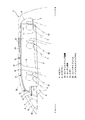
図1は、本発明の実施形態に係る車両の内装構造を構成するカーテンエアバッグ装置をカーテン部材の展開状態において車室内側から見た正面図である。車両Vにおいて、図中一点鎖線で示す部位1は運転席S1の横のドアDに形成された第1開口部(フロントウインド)、部位2は後部の前列席S2の横に形成された第2開口部(リヤウインド)、部位3は後部の後列席S3の横に形成された第3開口部(クォータウインド)である。
Hereinafter, embodiments of the present invention will be described in detail with reference to the drawings.
FIG. 1 is a front view of a curtain airbag device constituting an interior structure of a vehicle according to an embodiment of the present invention as viewed from the vehicle interior side in a deployed state of a curtain member. In the vehicle V, a
また、図中に示す部材4は車両Vの車体前端側に配置されたAピラー(フロントピラー)、部材5はドアDの前側でかつAピラー4の後方に配設され、上端部がAピラー4の上端部に近接するように配設されたサブピラー、部材6は、ドアDの後側のBピラー(前部センタピラー)、部材7は第2開口部2と第3開口部3との間に設けられたCピラー(後部センタピラー)、部材8は第2開口部2の後側のDピラー(クォータピラー)である。
Further, the member 4 shown in the figure is an A pillar (front pillar) disposed on the front end side of the vehicle V, the
本実施形態では、車両Vの3つの開口部1〜3が前後に並設された部分を1つの側部開口部と捉えている。すなわち、この側部開口部は、車体のルーフ側縁部によって構成される第1辺(上辺)と、Aピラー4で構成される第2辺(前辺)と、Dピラー8で構成される第3辺(後辺)と、ドアD及び車体のベルトラインによって構成される第4辺とによって略四角形状に、より具体的には第1辺が第4辺よりも短い略台形状になっている。
In the present embodiment, a portion where the three
Aピラー4とサブピラー5との間には、これらにより枠状に囲まれた三角窓9が配設されている。本実施形態では、三角窓9の上端部が運転席S1〜S3に着座した乗員Cの頭部の高さ位置近くまで延びる程大型なものとなっている。
Between the A pillar 4 and the
また、車両Vには、上記側部開口部に対応してこれを覆うことができるようにカーテンエアバッグ装置10が備えられている。カーテンエアバッグ装置10は、主に、ガスが注入されて膨張、展開するカーテン部材(カーテン本体)11と、カーテン部材11にガスを供給するガス供給装置としてのインフレータ12と、帯状をなすテザー13とを備えている。
Further, the vehicle V is provided with a
カーテン部材11は蛇腹状またはロール状に畳まれて、側部開口部の第1辺から第2辺上部及び第3辺上部に跨るように設けられたケーシング14に収容されている。
The
インフレータ12は、車両が所定の状態になったときに作動してガスを発生して供給するものであり、カーテン部材11にパイプ15によって繋がっている。所定の状態とは、例えば車両Vの衝突が予知されたときや、該車両Vの衝突が検出されたときであり、当該車両Vにはそれらの状態を検知するためのセンサと、該センサの出力を受けてそれら状態の発生を判定し、インフレータ12を作動させるコントローラとが設けられている。
The inflator 12 operates to generate and supply gas when the vehicle is in a predetermined state, and is connected to the
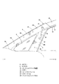
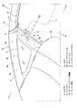
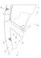
図2は、図1に示すカーテン部材の収納状態におけるAピラー、サブピラー周辺部位を拡大して示す正面図であり、図3は、Aピラー、サブピラー周辺部位を車室内上方から見た斜視図、図4は、カーテン部材の展開状態におけるAピラー、サブピラー周辺部位を拡大して示す正面図である。 FIG. 2 is an enlarged front view showing the area around the A pillar and the sub pillar in the storage state of the curtain member shown in FIG. 1, and FIG. 3 is a perspective view of the area around the A pillar and the sub pillar viewed from above the vehicle interior. FIG. 4 is an enlarged front view showing the vicinity of the A pillar and the sub-pillar in the deployed state of the curtain member.
カーテンエアバッグ装置10の内、折り畳まれたカーテン部材11を収納するケーシング14は、図2に示すように、サブピラー5の上端部より後方に延設されるルーフサイドレール20の側縁に沿って前後方向に延び、これに支持されている。具体的には、ケーシング14の前端部から後端部に亘って長手方向に複数のクリップ21、21が配設されており、ケーシング14は、この複数のクリップ21によりルーフサイドレール20に固定されている。
As shown in FIG. 2, the
また、カーテンエアバッグ装置10のテザー13は、カーテン部材11の収納状態において、図2、図3に示すように、その延び方向がサブピラー5の延び方向に略沿うように配設される一方、カーテン部材11が展開状態となった時には、図1に示すように車両前後方向に延びてカーテン部材11を前後方向に引張り、これに張力を作用させることができるようになっている。
Further, the
テザー13は、その一端部がサブピラー5の下端部より上方に離間する中間位置でバックル22に取付けられる一方、他端部がカーテン部材11の前端部に取付けられている。
The
ところで、上述した各ピラー4〜8においては、それぞれ車室内側を覆うべくピラートリムが固定されており、その内ピラー4、5は、共通のピラートリム23によって覆われている。
By the way, in each pillar 4-8 mentioned above, the pillar trim is fixed so that each vehicle interior side may be covered, The
ピラートリム23は、略逆V字形状に成形された樹脂製の部材であり、このピラートリム23においては、Aピラー4を覆う部位23aとサブピラー5を覆う部位23bとが一体的に形成されている。
The pillar trim 23 is a resin member formed in a substantially inverted V shape. In the pillar trim 23, a
また、ピラートリム23は、部位23a、23bのそれぞれが、Aピラー4、サブピラー5に対し、その長手方向に並ぶ複数のクリップ24、25により固定されるとともに、下端部が、車室の前端部にて各ピラー4、5の下方に位置するインストルメントパネル26(図1〜図3参照)に固定されている。
The pillar trim 23 is fixed to the A pillar 4 and the
カーテンエアバッグ装置10のテザー13は、カーテン部材11の収納状態において、サブピラー5とピラートリム23の部位23bとの間に収納されている。
The
また、ケーシング14は、その前端部がピラートリム23の上端部よりもさらに前方に延びており、該上端部に覆われている。
Further, the front end portion of the
本実施形態では、車両Vの側面において、上記所定の状態になった時には、インフレータ12に点火信号が入力され、該インフレータ12から供給された高圧ガスによりカーテン部材11の膨張部11a(図4参照)が膨張する。そして、このカーテン部材11は、不図示のルーフトリム及びピラートリム23の上端部を押し開いて、図1及び図4にて実線、図3にて二点鎖線で示すように、ルーフサイドレール20の下方に広がる側部開口部(開口部1〜3)を覆うように展開する。このため、車両Vの乗員C(図1参照)の頭部を拘束して保護するとともに、乗員Cの車外への飛び出しを防止できる。
In the present embodiment, when the predetermined state is reached on the side surface of the vehicle V, an ignition signal is input to the inflator 12 and the high-pressure gas supplied from the inflator 12 causes the
ここで、図4においては、図示の便宜上、運転席S1の乗員Cに対応する最前端の膨張部11aのみを示しているが、カーテン部材11には、座席S1〜S3に着座する各乗員Cの頭部の位置に対応して複数の膨張部11aが形成されており、インフレータ12からの高圧ガスをこの膨張部11aに対して供給することで、これを膨張させ、各乗員Cの頭部を保護するようになっている。また、カーテン部材11において、膨張部11a以外の部分は膨張しない非膨張膜11bとなっており、隣り合う膨張部11aは、非膨張部11bによって繋がっている。
Here, in FIG. 4, for convenience of illustration, only the foremost
また、膨張部11aのうち、運転席S1の乗員Cに対応する最前端のものについては、図4に示すように、側面視で車外側の面の所定位置に連結端部11cが形成され、テザー13の他端部が連結されている。このため、カーテン部材11の展開時には、膨張部11aの膨張に伴い、カーテン部材11の下縁が上記ベルトライン近傍まで移動するとともに、テザー13の他端部が、サブピラー5とピラートリム23の部位23bとの間から後方に移動し、テザー13が車両前後方向に延びた状態となる。
Further, among the
この場合、テザー13が車両前後方向に延びてカーテン部材11を引張ることで、カーテン部材11の車両前後方向にテンションラインを形成しながら、カーテン部材11に張力を作用させることができる。このため、乗員Cが車室内に留まるように保護して、乗員保護性能を向上させることができる。
In this case, the
そして、本実施形態では、上述したように、テザー13の一端部がサブピラー5の下端部よりも上方に離間した中間位置に連結されることで、展開状態にあるカーテン部材11の前方側がテザー13によってサブピラー5の上記中間位置に連結されることになる。このため、カーテン部材11の比較的下側のベルトライン近傍で車両前後方向に張力を作用させることができ、かつピラートリム23の部位23bの下端部がインストルメントパネル26に固定されることにより生じうるテザー13移動時の内倒れ現象を抑制することもできる。
In the present embodiment, as described above, one end portion of the
従って、本実施形態の構成により、ピラートリム23に付与される応力を低減して、ピラートリム23のクラックや破損を抑制することもできる。 Therefore, according to the configuration of the present embodiment, the stress applied to the pillar trim 23 can be reduced, and cracks and breakage of the pillar trim 23 can be suppressed.
また、本実施形態のように、ピラートリム23の内、部位23bとともにAピラー4を覆う部位23aの下端部がインストルメントパネル26に固定されている場合には、ピラートリム23の下端部全体が強固に固定されることにより、ピラートリム23にはより応力が発生し易い構成となっている。従って、特にこのような構成をなすものにおいて、テザー13の一端部をサブピラー5の上記中間位置に連結することで、ピラートリム23の取付剛性を向上させつつも、ピラートリム23における応力低減の効果をより顕著なものとすることができる。
Moreover, when the lower end part of the
また、テザー13が帯状をなしていることで、カーテン部材11の展開時にテザー13がピラートリム23に与える影響を小さく抑えることができる。なお、本実施形態では、テザー13を帯状としたが、必ずしもこれに限定されるものではなく、ピラートリム23への影響を小さく抑えることができるのであれば、例えば紐状や幅広の布状をなしていてもよい。
In addition, since the
また、カーテン部材11の前方側がテザー13によりサブピラー5の上記中間位置に連結されるため、テザー13により形成される連結部を短くすることができるとともに、乗員Cが着座する側を広く覆うことができる。
Further, since the front side of the
さらに、テザー13の他端部が、膨張部11aの所定部位(ここでは連結端部11c)に連結されることにより、カーテン部材11の展開時には、図5(a)に示すように、テザー13の他端部の位置を膨張部11aの膨張によって車両前方に移動させ、車両前後方向、即ちカーテン部材11に張力が作用する方向におけるテザー13の幅を、膨張しない場合の幅(テザー13の長さ)L1よりも短くすることができる。
Further, the other end portion of the
本実施形態では、膨張部11aの所定部位が膨張した場合に上記幅L1に比べて短くなった分、上記所定部位が膨張しない場合よりもテザー13の張力を大きくすることができ、カーテン部材11に対してより大きな張力を作用させることができる。
In the present embodiment, when the predetermined portion of the inflating
これに対し、図5(b)に示す比較例では、カーテン部材11の非膨張部11bに連結端部11c′を設定し、そこにテザー13′の他端部を連結している。この場合、カーテン11の展開前後、つまり膨張部11aの膨張の前後でテザー13′の上記幅は長さL2のままで変化しないため、膨張部11aが膨張した場合におけるテザー13′の張力を、所定部位(連結端部11c′)が膨張しない場合より大きくすることはできない。
On the other hand, in the comparative example shown in FIG. 5B, a connecting
ところで、本実施形態では、膨張部11aのうち、運転席S1の乗員Cに対応する最前端のものについては、これがカーテン部材11の収納状態において、ケーシング14の前端部、即ちピラートリム23の上端部に覆われる部分に収納されている。
By the way, in this embodiment, about the thing of the foremost end corresponding to the passenger | crew C of driver's seat S1 among the
このため、カーテン部材11の展開時には、膨張部11aの膨張による押圧力を利用して部位23bの上側部分をクリップ25から外すことが可能になり、サブピラー5から適宜車室内側に離間させることができる。従って、カーテン部材11の展開時には、サブピラー5と部位23bの上側部分との間隔を大きく確保でき、テザー13の他端部の後方(第1開口部1)側への移動を容易にして、テザー13を車両前後方向に延びる状態に確実に移行させることができる。
For this reason, when the
なお、本実施形態では、車両Vの前端側のAピラー4を第1ピラー、その後側のサブピラー5を第2ピラーと定義して説明したが、本発明は必ずしもこれに限定されるものではない。例えば、スポーツタイプの車両の場合には、後端側のピラーとその前側に位置するピラーとにより三角窓が形成されることもあり、このような場合に、車両後端側のピラーを第1ピラー、その前側のピラーを第2ピラーと定義して本発明を適用してもよい。この場合、上述したインストルメントパネル26に相当する部材は、車両後部両側壁に配設されるトリム部材となる。
In the present embodiment, the A pillar 4 on the front end side of the vehicle V is defined as the first pillar, and the
また、本実施形態に係る車両Vは、3列シートタイプの車両となっているが、必ずしもこれに限定されるものではない。 The vehicle V according to the present embodiment is a three-row seat type vehicle, but is not necessarily limited thereto.
この発明の構成と、上述の実施形態との対応において、
この発明の第1ピラーは、Aピラー4に対応し、
以下同様に、
第2ピラーは、サブピラー5に対応し、
エアバッグ手段は、カーテンエアバッグ装置10に対応し、
トリム部材は、インストルメントパネル26に対応し、
連結部は、テザー13に対応するも、
この発明は、上述の実施形態の構成のみに限定されるものではなく、多くの実施の形態を得ることができる。
In correspondence between the configuration of the present invention and the above-described embodiment,
The first pillar of the present invention corresponds to the A pillar 4,
Similarly,
The second pillar corresponds to the
The airbag means corresponds to the
The trim member corresponds to the
The connecting portion corresponds to the
The present invention is not limited only to the configuration of the above-described embodiment, and many embodiments can be obtained.
1…第1開口部
2…第2開口部
3…第3開口部
4…Aピラー
5…サブピラー
10…カーテンエアバッグ装置
11…カーテン部材
11a…膨張部
13…テザー
20…ルーフサイドレール
23…ピラートリム
26…インストルメントパネル
DESCRIPTION OF
Claims (5)
該第1ピラーの前後方向他方側に配設され、上端部が上記第1ピラーの上端部に近接して位置する第2ピラーと、
上記第1ピラーと上記第2ピラーとに固定され、これらピラーの車室内側を覆う一体形成されたピラートリムと、
上記第2ピラーの上端部より前後方向の更に他方側に延設するルーフサイドレールと、
該ルーフサイドレールに支持され、車両衝突検出/予知時に、上記ルーフサイドレールより下方に広がる車体の開口部を覆うようにカーテン部材が展開するエアバッグ手段とを備えた車両の内装構造であって、
上記ピラートリムの上記第2ピラーを覆う部位の下端部は、該第2ピラーの下方に位置するトリム部材に固定支持されるとともに、
上記カーテン部材は、展開状態においてベルトライン近傍までその下縁が移動するように展開し、
展開状態にある上記カーテン部材の前後方向一方側が、上記第2ピラーの下端部より離間した高さ方向の中間位置に対し、連結部により連結される
車両の内装構造。 A first pillar on one side of the vehicle longitudinal direction of the vehicle body;
A second pillar disposed on the other side in the front-rear direction of the first pillar and having an upper end positioned close to the upper end of the first pillar;
An integrally formed pillar trim fixed to the first pillar and the second pillar, and covering the interior side of the pillars;
A roof side rail extending from the upper end of the second pillar to the other side in the front-rear direction;
An interior structure of a vehicle comprising airbag means that is supported by the roof side rail and that deploys a curtain member so as to cover an opening of the vehicle body that extends downward from the roof side rail when a vehicle collision is detected / predicted. ,
A lower end portion of a portion covering the second pillar of the pillar trim is fixedly supported by a trim member located below the second pillar, and
The curtain member is deployed so that its lower edge moves to the vicinity of the belt line in the deployed state,
A vehicle interior structure in which one side in the front-rear direction of the curtain member in the unfolded state is connected by a connecting portion to an intermediate position in the height direction separated from the lower end portion of the second pillar.
請求項1記載の車両の内装構造。 The vehicle interior structure according to claim 1, wherein the connecting portion has a band shape or a string shape.
請求項2記載の車両の内装構造。 The connecting part is configured to be connected to a predetermined part of the inflating part of the curtain member in a side view, so that the tension of the connecting part is increased when the predetermined part is inflated than when the predetermined part is not inflated. The vehicle interior structure according to claim 2.
請求項1記載の車両の内装構造。 The interior structure of a vehicle according to claim 1, wherein a lower end portion of a portion covering the first pillar among the pillar trim is fixedly supported by the trim member.
該第1ピラーの前後方向他方側に配設され、上端部が上記第1ピラーの上端部に近接して位置する第2ピラーと、
上記第1ピラーと上記第2ピラーとに固定され、これらピラーの車室内側を覆う一体形成されたピラートリムと、
上記第2ピラーの上端部より前後方向の更に他方側に延設するルーフサイドレールと、
該ルーフサイドレールに支持され、車両衝突検出/予知時に、上記ルーフサイドレールより下方に広がる車体の開口部を覆うようにカーテン部材が展開するエアバッグ手段とを備えた車両の内装構造であって、
上記ピラートリムの上記第2ピラーを覆う部位の下端部は、該第2ピラーの下方に位置するトリム部材に固定支持されるとともに、
上記カーテン部材は、上記第2ピラーと連結部により連結されており、
収納状態の上記カーテン部材の膨張部が、上記ピラートリムの少なくとも上端部により覆われるように構成される
車両の内装構造。 A first pillar on one side of the vehicle longitudinal direction of the vehicle body;
A second pillar disposed on the other side in the front-rear direction of the first pillar and having an upper end positioned close to the upper end of the first pillar;
An integrally formed pillar trim fixed to the first pillar and the second pillar, and covering the interior side of the pillars;
A roof side rail extending from the upper end of the second pillar to the other side in the front-rear direction;
An interior structure of a vehicle comprising airbag means that is supported by the roof side rail and that deploys a curtain member so as to cover an opening of the vehicle body that extends downward from the roof side rail when a vehicle collision is detected / predicted. ,
A lower end portion of a portion covering the second pillar of the pillar trim is fixedly supported by a trim member located below the second pillar, and
The curtain member is connected to the second pillar by a connecting portion,
A vehicle interior structure configured such that an inflated portion of the curtain member in a stored state is covered with at least an upper end portion of the pillar trim.
Priority Applications (1)
| Application Number | Priority Date | Filing Date | Title |
|---|---|---|---|
| JP2008164133A JP5163309B2 (en) | 2008-06-24 | 2008-06-24 | Vehicle interior structure |
Applications Claiming Priority (1)
| Application Number | Priority Date | Filing Date | Title |
|---|---|---|---|
| JP2008164133A JP5163309B2 (en) | 2008-06-24 | 2008-06-24 | Vehicle interior structure |
Publications (2)
| Publication Number | Publication Date |
|---|---|
| JP2010006100A true JP2010006100A (en) | 2010-01-14 |
| JP5163309B2 JP5163309B2 (en) | 2013-03-13 |
Family
ID=41587094
Family Applications (1)
| Application Number | Title | Priority Date | Filing Date |
|---|---|---|---|
| JP2008164133A Active JP5163309B2 (en) | 2008-06-24 | 2008-06-24 | Vehicle interior structure |
Country Status (1)
| Country | Link |
|---|---|
| JP (1) | JP5163309B2 (en) |
Cited By (6)
| Publication number | Priority date | Publication date | Assignee | Title |
|---|---|---|---|---|
| JP2010012925A (en) * | 2008-07-03 | 2010-01-21 | Mazda Motor Corp | Interior structure of vehicle |
| JP2012020719A (en) * | 2010-07-16 | 2012-02-02 | Autoliv Development Ab | Curtain airbag |
| JP2014015103A (en) * | 2012-07-06 | 2014-01-30 | Autoliv Development Ab | Curtain airbag for vehicle and curtain airbag structure for vehicle |
| JP2016041587A (en) * | 2015-12-28 | 2016-03-31 | オートリブ ディベロップメント エービー | Mounting structure of vehicular curtain airbag |
| JP2019031167A (en) * | 2017-08-07 | 2019-02-28 | トヨタ自動車株式会社 | Mounting structure of curtain airbag device and curtain airbag expansion method |
| EP3498541A1 (en) * | 2017-12-12 | 2019-06-19 | Toyota Jidosha Kabushiki Kaisha | Mounting structure for curtain airbag device |
Citations (2)
| Publication number | Priority date | Publication date | Assignee | Title |
|---|---|---|---|---|
| JP2007131262A (en) * | 2005-11-14 | 2007-05-31 | Suzuki Motor Corp | Interior material mounting structure around front pillar of automobile |
| JP2007196729A (en) * | 2006-01-24 | 2007-08-09 | Suzuki Motor Corp | Head protection airbag mounting structure for vehicle |
-
2008
- 2008-06-24 JP JP2008164133A patent/JP5163309B2/en active Active
Patent Citations (2)
| Publication number | Priority date | Publication date | Assignee | Title |
|---|---|---|---|---|
| JP2007131262A (en) * | 2005-11-14 | 2007-05-31 | Suzuki Motor Corp | Interior material mounting structure around front pillar of automobile |
| JP2007196729A (en) * | 2006-01-24 | 2007-08-09 | Suzuki Motor Corp | Head protection airbag mounting structure for vehicle |
Cited By (11)
| Publication number | Priority date | Publication date | Assignee | Title |
|---|---|---|---|---|
| JP2010012925A (en) * | 2008-07-03 | 2010-01-21 | Mazda Motor Corp | Interior structure of vehicle |
| JP2012020719A (en) * | 2010-07-16 | 2012-02-02 | Autoliv Development Ab | Curtain airbag |
| JP2014015103A (en) * | 2012-07-06 | 2014-01-30 | Autoliv Development Ab | Curtain airbag for vehicle and curtain airbag structure for vehicle |
| JP2016041587A (en) * | 2015-12-28 | 2016-03-31 | オートリブ ディベロップメント エービー | Mounting structure of vehicular curtain airbag |
| JP2019031167A (en) * | 2017-08-07 | 2019-02-28 | トヨタ自動車株式会社 | Mounting structure of curtain airbag device and curtain airbag expansion method |
| EP3498541A1 (en) * | 2017-12-12 | 2019-06-19 | Toyota Jidosha Kabushiki Kaisha | Mounting structure for curtain airbag device |
| JP2019104383A (en) * | 2017-12-12 | 2019-06-27 | トヨタ自動車株式会社 | Mounting structure of curtain airbag device |
| CN109955823A (en) * | 2017-12-12 | 2019-07-02 | 丰田自动车株式会社 | Mounting structure for curtain airbag |
| US10730561B2 (en) | 2017-12-12 | 2020-08-04 | Toyota Jidosha Kabushiki Kaisha | Mounting structure for curtain airbag device |
| CN109955823B (en) * | 2017-12-12 | 2021-10-15 | 丰田自动车株式会社 | Mounting structure for curtain airbag device |
| JP6996270B2 (en) | 2017-12-12 | 2022-01-17 | トヨタ自動車株式会社 | Mounting structure of curtain airbag device |
Also Published As
| Publication number | Publication date |
|---|---|
| JP5163309B2 (en) | 2013-03-13 |
Similar Documents
| Publication | Publication Date | Title |
|---|---|---|
| US9027954B2 (en) | Airbag device | |
| JP5267579B2 (en) | Passenger car head protection airbag device | |
| KR101917330B1 (en) | Curtain air-bag device | |
| JP6508038B2 (en) | Vehicle seat with side air bag device | |
| JP2019031167A (en) | Mounting structure of curtain airbag device and curtain airbag expansion method | |
| JP4665668B2 (en) | Head protection airbag device | |
| JP5606876B2 (en) | Curtain airbag | |
| JP5163309B2 (en) | Vehicle interior structure | |
| US10723303B2 (en) | Vehicle curtain airbag device | |
| JP2009292441A (en) | Curtain airbag bracket and curtain airbag apparatus | |
| WO2009144971A1 (en) | Head-restraining airbag system | |
| JP2008137458A (en) | Airbag device | |
| JP2007261512A (en) | Rear collision air bag device | |
| JP6420157B2 (en) | Airbag | |
| JP2007076517A (en) | Head protection airbag device | |
| JP2008168781A (en) | Curtain airbag layout structure | |
| JP4987013B2 (en) | Curtain airbag device | |
| JP4631778B2 (en) | Airbag device | |
| JP2010083240A (en) | Air-bag and airbag device | |
| JP5034552B2 (en) | Rear structure of vehicle with curtain airbag device | |
| JP4721987B2 (en) | Head protection airbag device | |
| JP2016124497A (en) | Air bag | |
| JP6580480B2 (en) | Curtain airbag device | |
| JP2002053003A (en) | Head part protective air bag device | |
| JP2006182255A (en) | Protecting device corresponding to rolling of vehicle |
Legal Events
| Date | Code | Title | Description |
|---|---|---|---|
| A621 | Written request for application examination |
Free format text: JAPANESE INTERMEDIATE CODE: A621 Effective date: 20110523 |
|
| A521 | Written amendment |
Free format text: JAPANESE INTERMEDIATE CODE: A523 Effective date: 20120329 |
|
| A131 | Notification of reasons for refusal |
Free format text: JAPANESE INTERMEDIATE CODE: A131 Effective date: 20120828 |
|
| A977 | Report on retrieval |
Free format text: JAPANESE INTERMEDIATE CODE: A971007 Effective date: 20120831 |
|
| A521 | Written amendment |
Free format text: JAPANESE INTERMEDIATE CODE: A523 Effective date: 20121024 |
|
| TRDD | Decision of grant or rejection written | ||
| A01 | Written decision to grant a patent or to grant a registration (utility model) |
Free format text: JAPANESE INTERMEDIATE CODE: A01 Effective date: 20121120 |
|
| A61 | First payment of annual fees (during grant procedure) |
Free format text: JAPANESE INTERMEDIATE CODE: A61 Effective date: 20121203 |
|
| FPAY | Renewal fee payment (event date is renewal date of database) |
Free format text: PAYMENT UNTIL: 20151228 Year of fee payment: 3 |
|
| R150 | Certificate of patent or registration of utility model |
Ref document number: 5163309 Country of ref document: JP Free format text: JAPANESE INTERMEDIATE CODE: R150 Free format text: JAPANESE INTERMEDIATE CODE: R150 |