JP6848839B2 - Vehicle curtain airbag device - Google Patents
Vehicle curtain airbag device Download PDFInfo
- Publication number
- JP6848839B2 JP6848839B2 JP2017230585A JP2017230585A JP6848839B2 JP 6848839 B2 JP6848839 B2 JP 6848839B2 JP 2017230585 A JP2017230585 A JP 2017230585A JP 2017230585 A JP2017230585 A JP 2017230585A JP 6848839 B2 JP6848839 B2 JP 6848839B2
- Authority
- JP
- Japan
- Prior art keywords
- vehicle
- curtain airbag
- pillar garnish
- main body
- width direction
- Prior art date
- Legal status (The legal status is an assumption and is not a legal conclusion. Google has not performed a legal analysis and makes no representation as to the accuracy of the status listed.)
- Active
Links
Images


Classifications
-
- B—PERFORMING OPERATIONS; TRANSPORTING
- B60—VEHICLES IN GENERAL
- B60R—VEHICLES, VEHICLE FITTINGS, OR VEHICLE PARTS, NOT OTHERWISE PROVIDED FOR
- B60R21/00—Arrangements or fittings on vehicles for protecting or preventing injuries to occupants or pedestrians in case of accidents or other traffic risks
- B60R21/02—Occupant safety arrangements or fittings, e.g. crash pads
- B60R21/16—Inflatable occupant restraints or confinements designed to inflate upon impact or impending impact, e.g. air bags
- B60R21/20—Arrangements for storing inflatable members in their non-use or deflated condition; Arrangement or mounting of air bag modules or components
- B60R21/213—Arrangements for storing inflatable members in their non-use or deflated condition; Arrangement or mounting of air bag modules or components in vehicle roof frames or pillars
-
- B—PERFORMING OPERATIONS; TRANSPORTING
- B60—VEHICLES IN GENERAL
- B60R—VEHICLES, VEHICLE FITTINGS, OR VEHICLE PARTS, NOT OTHERWISE PROVIDED FOR
- B60R21/00—Arrangements or fittings on vehicles for protecting or preventing injuries to occupants or pedestrians in case of accidents or other traffic risks
- B60R21/02—Occupant safety arrangements or fittings, e.g. crash pads
- B60R21/16—Inflatable occupant restraints or confinements designed to inflate upon impact or impending impact, e.g. air bags
- B60R21/20—Arrangements for storing inflatable members in their non-use or deflated condition; Arrangement or mounting of air bag modules or components
- B60R21/215—Arrangements for storing inflatable members in their non-use or deflated condition; Arrangement or mounting of air bag modules or components characterised by the covers for the inflatable member
- B60R21/216—Arrangements for storing inflatable members in their non-use or deflated condition; Arrangement or mounting of air bag modules or components characterised by the covers for the inflatable member comprising tether means for limitation of cover motion during deployment
-
- B—PERFORMING OPERATIONS; TRANSPORTING
- B60—VEHICLES IN GENERAL
- B60R—VEHICLES, VEHICLE FITTINGS, OR VEHICLE PARTS, NOT OTHERWISE PROVIDED FOR
- B60R21/00—Arrangements or fittings on vehicles for protecting or preventing injuries to occupants or pedestrians in case of accidents or other traffic risks
- B60R21/02—Occupant safety arrangements or fittings, e.g. crash pads
- B60R21/16—Inflatable occupant restraints or confinements designed to inflate upon impact or impending impact, e.g. air bags
- B60R21/23—Inflatable members
- B60R21/231—Inflatable members characterised by their shape, construction or spatial configuration
- B60R21/232—Curtain-type airbags deploying mainly in a vertical direction from their top edge
-
- B—PERFORMING OPERATIONS; TRANSPORTING
- B60—VEHICLES IN GENERAL
- B60R—VEHICLES, VEHICLE FITTINGS, OR VEHICLE PARTS, NOT OTHERWISE PROVIDED FOR
- B60R21/00—Arrangements or fittings on vehicles for protecting or preventing injuries to occupants or pedestrians in case of accidents or other traffic risks
- B60R21/02—Occupant safety arrangements or fittings, e.g. crash pads
- B60R21/16—Inflatable occupant restraints or confinements designed to inflate upon impact or impending impact, e.g. air bags
- B60R21/26—Inflatable occupant restraints or confinements designed to inflate upon impact or impending impact, e.g. air bags characterised by the inflation fluid source or means to control inflation fluid flow
-
- B—PERFORMING OPERATIONS; TRANSPORTING
- B60—VEHICLES IN GENERAL
- B60R—VEHICLES, VEHICLE FITTINGS, OR VEHICLE PARTS, NOT OTHERWISE PROVIDED FOR
- B60R13/00—Elements for body-finishing, identifying, or decorating; Arrangements or adaptations for advertising purposes
- B60R13/02—Internal Trim mouldings ; Internal Ledges; Wall liners for passenger compartments; Roof liners
- B60R13/0212—Roof or head liners
-
- B—PERFORMING OPERATIONS; TRANSPORTING
- B60—VEHICLES IN GENERAL
- B60R—VEHICLES, VEHICLE FITTINGS, OR VEHICLE PARTS, NOT OTHERWISE PROVIDED FOR
- B60R21/00—Arrangements or fittings on vehicles for protecting or preventing injuries to occupants or pedestrians in case of accidents or other traffic risks
- B60R21/02—Occupant safety arrangements or fittings, e.g. crash pads
- B60R21/16—Inflatable occupant restraints or confinements designed to inflate upon impact or impending impact, e.g. air bags
- B60R21/23—Inflatable members
- B60R21/231—Inflatable members characterised by their shape, construction or spatial configuration
- B60R21/2334—Expansion control features
- B60R21/2338—Tethers
- B60R2021/23386—External tether means
Description
本発明は、車両用カーテンエアバッグ装置に関する。 The present invention relates to a vehicle curtain airbag device.
特許文献1には、ルーフサイドレールの下方に配設されるメインセル領域と、Aピラー(フロントピラー)の下方に配設されるサブセル領域とを備えたカーテン袋体(カーテンエアバッグ本体)が開示されている。また、特許文献1では、サブセル領域を車両上方側へ折り返すことで、膨張時にカーテン袋体の前端部の厚みが増えるように構成されている。
引用文献1のように膨張時にカーテンエアバッグ本体の前端部の厚みが増えるようにすれば、乗員の頭部が首部の軸線回りに回転する頭部回転傷害(Brain Rotational Injury Criterion:BrIC)の発生を抑制することができる。しかしながら、メインセル領域及びサブセル領域の2つのエアバッグを車両幅方向に並べて膨張させただけでは、効果的にカーテンエアバッグ本体を車両幅方向内側へ押し出すことができない可能性があり、BrICを安定して低減する観点で改善の余地がある。
If the thickness of the front end of the curtain airbag body is increased as in
本発明は上記事実を考慮し、乗員の保護性能を良好に維持することができる車両用カーテンエアバッグ装置を得ることを目的とする。 In consideration of the above facts, an object of the present invention is to obtain a vehicle curtain airbag device capable of maintaining good occupant protection performance.
請求項1に記載の発明に係る車両用カーテンエアバッグ装置は、フロントピラー及びルーフサイドレールに跨って収納され、ガスが供給されることでサイドウインドウガラスに沿って車両下方側へ膨張展開するカーテンエアバッグ本体と、前記カーテンエアバッグ本体に形成され、前記カーテンエアバッグ本体の膨張展開状態でフロントピラーガーニッシュとルーフヘッドライニングとの境界よりも車両前方側を車両上下方向に延びて、前記カーテンエアバッグ本体の上部を前後に分断する切込部と、前記カーテンエアバッグ本体における前記切込部よりも車両前方側の前膨張部と車両本体とを連結し、前記前膨張部を前記フロントピラーガーニッシュの車両幅方向外側で膨張させる連結部材と、前記フロントピラーガーニッシュを前記前膨張部が膨張する前の状態における初期位置と、該初期位置よりも車両幅方向内側で前記前膨張部が膨張した状態における膨張位置との間で車両幅方向に移動可能に保持する保持部材と、を有する。
The vehicle curtain airbag device according to the invention according to
請求項1に記載の発明では、フロントピラー及びルーフサイドレールに跨ってカーテンエアバッグ本体が収納されており、このカーテンエアバッグ本体は、ガスが供給されることでサイドウインドウガラスに沿って車両下方側へ膨張展開される。また、カーテンエアバッグ本体には、車両上下方向に延びてカーテンエアバッグ本体の上部を前後に分断する切込部が形成されている。ここで、切込部は、カーテンエアバッグ本体の膨張展開状態でフロントピラーガーニッシュとルーフヘッドライニングとの境界よりも車両前方側に形成されている。このため、カーテンエアバッグ本体における切込部よりも車両後方側の部位の前部が側面視でフロントピラーガーニッシュと重なる位置に配置されることとなる。
In the invention according to
また、カーテンエアバッグ本体における切込部よりも車両前方側の前膨張部と車両本体とが連結部材で連結されており、前膨張部はフロントピラーガーニッシュの車両幅方向外側で膨張される。ここで、フロントピラーガーニッシュは、保持部材によって車両幅方向に移動可能に保持されている。このため、フロントピラーガーニッシュは、前膨張部が膨張することで、初期位置から膨張位置へ車両幅方向内側に移動される。これにより、切込部よりも車両後方側の部位の前部を車両幅方向内側へ移動させることができ、BrICを低減することができる。特に、フロントピラーガーニッシュによってカーテンエアバッグ本体を車両幅方向内側へ移動させる構成とすることで、ピラーガーニッシュの車両幅方向内側の面でカーテンエアバッグ本体を押し出すことができる。 Further, the front expansion portion on the front side of the vehicle and the vehicle body are connected by a connecting member from the notch portion in the curtain airbag body, and the front expansion portion is expanded on the outside in the vehicle width direction of the front pillar garnish. Here, the front pillar garnish is movably held in the vehicle width direction by the holding member. Therefore, the front pillar garnish is moved inward in the vehicle width direction from the initial position to the expansion position by expanding the front expansion portion. As a result, the front portion of the portion rearward of the vehicle with respect to the cut portion can be moved inward in the vehicle width direction, and BrIC can be reduced. In particular, by configuring the front pillar garnish to move the curtain airbag body inward in the vehicle width direction, the curtain airbag body can be pushed out on the inner surface of the pillar garnish in the vehicle width direction.
請求項2に記載の発明に係る車両用カーテンエアバッグ装置は、請求項1において、前記連結部材の少なくとも上部は、前記カーテンエアバッグ本体の膨張展開状態における車両側面視で前記フロントピラーガーニッシュと重なる位置に配置されている。
In the vehicle curtain airbag device according to the second aspect of the present invention, in
請求項2に記載の発明では、連結部材の上部が車両側面視でフロントピラーガーニッシュよりも下方に配置された構成と比較して、前膨張部をより確実にフロントピラーガーニッシュの車両幅方向外側に留めることができ、前膨張部を効果的にフロントピラーガーニッシュの車両幅方向外側で膨張させることができる。
In the invention according to
請求項3に記載の発明に係る車両用カーテンエアバッグ装置は、請求項1又は2において、前記カーテンエアバッグ本体における前記切込部よりも車両後方側の後膨張部には、前記カーテンエアバッグ本体へガスが供給されるガス供給路が設けられており、膨張展開状態の前記カーテンエアバッグ本体における前記フロントピラーガーニッシュと前記ルーフヘッドライニングとの境界の下方側には、非膨張部が設けられている。 The vehicle curtain airbag device according to the third aspect of the present invention has the curtain airbag in the rear expansion portion of the curtain airbag main body on the rear side of the vehicle with respect to the notch portion in the first or second aspect. A gas supply path for supplying gas to the main body is provided, and a non-expandable portion is provided below the boundary between the front pillar garnish and the roof head lining in the expanded and deployed curtain airbag main body. ing.
請求項3に記載の発明では、カーテンエアバッグ本体の後膨張部にガス供給路が設けられている。また、カーテンエアバッグ本体におけるフロントピラーガーニッシュとルーフヘッドライニングとの境界の下方側に非膨張部が設けられている。これにより、カーテンエアバッグ本体は、前膨張部よりも後膨張部の方が僅かに先に膨張する。この結果、前膨張部が膨張してフロントピラーガーニッシュが車両幅方向内側へ移動する前に、後膨張部をフロントピラーガーニッシュの車両幅方向内側に展開させることができる。
In the invention according to
請求項4に記載の発明に係る車両用カーテンエアバッグ装置は、請求項1又は2において、前記カーテンエアバッグ本体における前記切込部よりも車両後方側の後膨張部には、前記カーテンエアバッグ本体へガスが供給されるガス供給路が設けられており、前記切込部の下端から車両後方側かつ車両下方側へ向かって非膨張部が設けられている。 The vehicle curtain airbag device according to the fourth aspect of the present invention has the curtain airbag in the rear expansion portion on the rear side of the vehicle with respect to the notch portion in the curtain airbag main body in the first or second aspect. A gas supply path for supplying gas to the main body is provided, and a non-expandable portion is provided from the lower end of the cut portion toward the rear side of the vehicle and the lower side of the vehicle.
請求項4に記載の発明では、切込部の下端から車両後方側かつ車両下方側へ向かって非膨張部が設けられている。このため、非膨張部の下側のみで前膨張部と後膨張部とが連通されることとなり、非膨張部の上下両側で前膨張部と後膨張部とが連通された構造と比較して、前膨張部及び後膨張部の膨張完了までの時間差を大きくすることができる。
In the invention according to
請求項5に記載の発明に係る車両用カーテンエアバッグ装置は、請求項1〜4の何れか1項において、前記保持部材は、一端部がピラーインナパネルに固定され、他端部が前記フロントピラーガーニッシュに形成された取付座に挿通された弾性変形可能な軸部と、前記軸部の先端部に形成されると共に、前記取付座に係止可能なアンカ部と、を含んで構成されている。
In the vehicle curtain airbag device according to the fifth aspect of the present invention, in any one of
請求項5に記載の発明では、前膨張部の膨張時には、軸部の先端部に形成されたアンカ部が取付座に係止されることで、フロントピラーガーニッシュの車両幅方向の移動を制限することができる。
In the invention according to
以上説明したように、請求項1に係る車両用カーテンエアバッグ装置によれば、乗員の保護性能を良好に維持することができる、という優れた効果を奏する。
As described above, the vehicle curtain airbag device according to
請求項2に係る車両用カーテンエアバッグ装置によれば、フロントピラーガーニッシュを確実に車両幅方向内側へ移動させることができる、という優れた効果を奏する。
According to the vehicle curtain airbag device according to
請求項3に係る車両用カーテンエアバッグ装置によれば、安定して後膨張部を車両幅方向内側へ移動させることができる、という優れた効果を奏する。
According to the vehicle curtain airbag device according to
請求項4に係る車両用カーテンエアバッグ装置によれば、非膨張部の上下両側で前膨張部と後膨張部とが連通された構造と比較して、より安定して後膨張部を車両幅方向内側へ移動させることができる、という優れた効果を奏する。
According to the vehicle curtain airbag device according to
請求項5に係る車両用カーテンエアバッグ装置によれば、簡易な構成でフロントピラーガーニッシュを車両幅方向に移動可能に保持することができる、という優れた効果を奏する。
According to the vehicle curtain airbag device according to
<第1実施形態>
以下、図面を参照して第1実施形態に係る車両用カーテンエアバッグ装置10について説明する。なお、各図中に適宜示される矢印FRは車両前方向を示し、矢印UPは車両上方向を示し、矢印RHは車両右側を示している。以下、前後左右上下の方向を用いて説明する場合、特に断りのない限り、車両前後方向の前後、車両幅方向の左右、車両上下方向の上下を示すものとする。
<First Embodiment>
Hereinafter, the vehicle
(カーテンエアバッグ装置の全体構成)
図1に示されるように、車両用カーテンエアバッグ装置10は、車両12に搭載された乗員保護装置であり、カーテンエアバッグ本体14と、インフレータ16と、連結部材としての三角ストラップ17とを含んで構成されている。カーテンエアバッグ本体14は、インフレータ16からガスが供給されることで、サイドウインドウガラス18に沿って車両下方側へ膨張展開する。
(Overall configuration of curtain airbag device)
As shown in FIG. 1, the vehicle
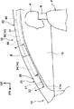
このカーテンエアバッグ本体14は、膨張展開する前の状態では、図2に示されるように、ロール状に折畳まれて長尺状にされた上で、車室側部の上端部に設けられたフロントピラー20及びルーフサイドレール22に跨ってインフレータ16と共に収納される。
In the state before expansion and deployment, the curtain airbag
フロントピラー20は、車両前部を車両上下方向に沿って延在された骨格部材であり、図4に示されるように、フロントピラーインナパネル24(以下、適宜「ピラーインナパネル24」と称する。)と、図示しないフロントピラーアウタパネル(以下、適宜「ピラーアウタパネル」と称する。)とを含んで構成されている。
The
ピラーインナパネル24は、剛板で形成されて骨格部材の車両幅方向内側を構成しており、このピラーインナパネル24の車両幅方向外側には、図示しないピラーアウタパネルが配置されている。そして、ピラーインナパネル24とピラーアウタパネルとが接合されて閉断面が構成される。
The pillar
このフロントピラー20は、フロントピラーガーニッシュ26(以下、適宜「ピラーガーニッシュ26」と称する。)によって車室内側から覆われている。ピラーガーニッシュ26は、ピラーインナパネル24よりも車両幅方向内側に配置されて樹脂で形成された内装材であり、このピラーインナパネル24とピラーガーニッシュ26との間にカーテンエアバッグ本体14が折り畳まれた状態で収納されている。なお、ピラーガーニッシュ26の前端部は、周知の構造と同様にインストルメントパネルの取付孔に挿入されている。
The
また、ピラーガーニッシュ26には、保持部材としてのテザークリップ52が係止される取付座50が形成されている。取付座50は、ピラーガーニッシュ26から車両幅方向外側へ延出された横壁部50Aと、横壁部50Aの先端部から車両後方側へ延出された縦壁部50Bとを含んで構成されており、縦壁部50Bには挿通孔50Cが形成されている。そして、この挿通孔50Cには、テザークリップ52の軸部52Aが挿通されている。
Further, the
テザークリップ52は、軸部52Aと、固定部52Bと、アンカ部52Cとを含んで構成されている。軸部52Aは、長尺状の部位であり、弾性変形可能に形成されている。そして、この軸部52Aの一端部には固定部52Bが設けられており、この固定部52Bはピラーインナパネル24に固定されている。一方、軸部52Aの他端部にはアンカ部52Cが設けられている。アンカ部52Cは、取付座50に挿通された軸部52Aの端部に形成されており、この取付座50に係止可能な大きさに形成されている。
The
ここで、図4のようにカーテンエアバッグ本体14の膨張展開前の状態では、ピラーインナパネル24とピラーガーニッシュ26との間の空間が狭いため、テザークリップ52の軸部52Aの先端側がピラーガーニッシュ26に当たって曲げられている(弾性変形されている)。図3に示されるように、カーテンエアバッグ本体14の膨張展開状態では、後述する前膨張部34がピラーインナパネル24とピラーガーニッシュ26との間で膨張するため、このピラーインナパネル24とピラーガーニッシュ26との間の空間が広げられる。これにより、テザークリップ52のアンカ部52Cが取付座50に係止される位置までピラーガーニッシュ26が車両幅方向内側へ移動する。
Here, as shown in FIG. 4, in the state before the expansion and deployment of the curtain airbag
図4に示されるように、ルーフサイドレール22は、車両12の上部を車両前後方向に延在された骨格部材であり、レールインナパネル28と、図示しないレールアウタパネルとを含んで構成されている。レールインナパネル28は、剛板で形成されて骨格部材の車両幅方向内側を構成しており、このレールインナパネル28の車両幅方向外側には、図示しないレールアウタパネルが配置されている。そして、レールインナパネル28とレールアウタパネルとが接合されて閉断面が構成される。
As shown in FIG. 4, the
また、ルーフサイドレール22は、ルーフヘッドライニング30によって車室内側から覆われている。そして、このルーフサイドレール22とルーフヘッドライニング30との間にカーテンエアバッグ本体14が折り畳まれた状態で収納されている。
Further, the
図1に示されるように、ピラーガーニッシュ26とルーフヘッドライニング30との境界は、見切りBとされている。そして、見切りBよりも車両前方側にピラーガーニッシュ26が配置されており、見切りBよりも車両後方側にルーフヘッドライニング30が配置されている。
As shown in FIG. 1, the boundary between the
カーテンエアバッグ本体14は、例えばナイロン系又はポリエステル系の布材が切り出されて形成された2枚の基布が互いに重ね合わされると共に外周縁部を互いに縫製されることにより袋状に形成されている。なお、カーテンエアバッグ本体14の製造方法は、上記に限らず、ワンピースウーブン(One Piece Woven)方式によってカーテンエアバッグ本体14を一体に袋織りにしてもよい。
The curtain airbag
カーテンエアバッグ本体14の上部には切込部14Aが形成されており、カーテンエアバッグ本体14は、この切込部14Aよりも車両前方側に位置する前膨張部34と、車両後方側に位置する後膨張部36とを含んで構成されている。
A
切込部14Aは、カーテンエアバッグ本体14の膨張展開状態で見切りB(フロントピラーガーニッシュ26とルーフヘッドライニング30との境界)よりも車両前方側を車両上下方向に延びている。そして、この切込部14Aによってカーテンエアバッグ本体14の上部が前後に分断されている。また、本実施形態の切込部14Aは、カーテンエアバッグ本体14の上端部からピラーガーニッシュ26の下端よりもやや下方まで形成されている。このため、前膨張部34と後膨張部36とは、切込部14Aよりも下方側で互いに連通している。
The
前膨張部34は、カーテンエアバッグ本体14の前部を構成しており、この前膨張部34の上部には三角ストラップ17が取り付けられている。三角ストラップ17は、車両側面視で略三角状に形成された帯状の部材であり、三角ストラップ17の前端部17Aは、図3及び図4に示されるようにボルト32及びウエルドナット33によってピラーインナパネル24に締結されている。また、図1に示されるように、三角ストラップ17の後端部17Bは、カーテンエアバッグ本体14の前膨張部34における上端部に縫製されている(縫製部S1)。このようにして、三角ストラップ17によって前膨張部34がピラーインナパネル24(車両本体)と連結されている。
The
また、三角ストラップ17の少なくとも上部は、ピラーガーニッシュ26と重なる位置に配置されており、本実施形態では一例として、三角ストラップ17の後端部かつ下端部の一部を除いてピラーガーニッシュ26と重なる位置に配置されている。
Further, at least the upper portion of the
ここで、図2及び図4に示されるように、カーテンエアバッグ本体14の膨張展開前の状態では、三角ストラップ17が緩んだ状態となっている。一方、図1及び図3に示されるように、カーテンエアバッグ本体14の膨張展開状態では、三角ストラップ17が引っ張られることで、前膨張部34に対してピラーインナパネル24側へ向かう張力が作用する。このため、前膨張部34(の上部34A)は、ピラーインナパネル24とピラーガーニッシュ26との間の空間に留まり、この空間内で膨張するように構成されている。
Here, as shown in FIGS. 2 and 4, the
図1に示されるように、切込部14Aを挟んで前膨張部34の車両後方側には後膨張部36が設けられており、この後膨張部36は、図示しない後席まで延在されている。ここで、後膨張部36の上部36Aは、ピラーガーニッシュ26の車両幅方向内側及びルーフヘッドライニング30の車両幅方向内側で膨張展開するように構成されている。このため、カーテンエアバッグ本体14は、切込部14Aによってピラーガーニッシュ26を車両幅方向に跨ぐようにして膨張展開される(図3参照)。
As shown in FIG. 1, a
後膨張部36の上縁部には、複数のタブ40が車両前後方向に並んで設けられている。複数のタブ40は、例えば、カーテンエアバッグ本体14の基布と同様の布材によって形成されており、後膨張部36の上縁部から車両上方側へ延出されている。そして、これらのタブ40は、図示しないボルト及びウエルドナットによってルーフサイドレール22のレールインナパネル28に締結されている。
A plurality of
また、後膨張部36の前部には、膨張しない非膨張部14Bが設けられている。非膨張部14Bは、カーテンエアバッグ本体14の膨張展開状態で見切りBの車両下方側に設けられており、車両上下方向に延在されている。このため、インフレータ16から後膨張部36へ供給されたガスは、非膨張部14Bよりも上側又は非膨張部14Bよりも下側を流れて前膨張部34へ供給される。なお、図1の後膨張部36に図示された二点鎖線48で囲まれた領域は、斜め衝突時に乗員Pの頭部Hを拘束する領域である。
Further, a
後膨張部36の上端部において、乗員Pの着座位置よりも車両後方側から車両上方側かつ車両後方側へガス供給路42が延出されている。このガス供給路42は、ルーフヘッドライニング30の車両幅方向外側に位置しており、インフレータ16に接続されている。
At the upper end of the
インフレータ16は、所謂シリンダタイプのインフレータであり、車両前後方向を軸方向としてルーフサイドレール22に固定されている。また、インフレータ16の前端部には、ガス噴出部16Aが設けられており、このガス噴出部16Aには複数の噴出口が形成されている。そして、インフレータ16が作動することで、このガス噴出部16Aからガスが噴出され、ガス供給路42を通じてカーテンエアバッグ本体14へガスが供給される。
The inflator 16 is a so-called cylinder type inflator, and is fixed to the
インフレータ16は、ECU(Electronic Control Unit)46と電気的に接続されている。このECU46には、側突センサ、ロールオーバセンサ及び斜突センサ(何れも図示省略)が電気的に接続されている。側突センサは、車両12の側面衝突(の不可避)を予測又は検出してECU46に信号を出力するように構成されている。ロールオーバセンサは、車両12のロールオーバ(の不可避)を予測又は検出してECU46に信号を出力するように構成されている。また、斜突センサは、車両12の斜め衝突(の不可避)を予測又は検出してECU46に信号を出力するように構成されている。なお、本実施形態において、斜め衝突(MDB斜突、オブリーク衝突)とは、例えばNHTSAにおいて規定されている斜め前方からの衝突(一例として、衝突相手方との相対角15°、車両幅方向のラップ量35%程度の衝突)とされている。本実施形態では、一例として相対速度90km/hrでの斜め衝突が想定されている。
The inflator 16 is electrically connected to an ECU (Electronic Control Unit) 46. A side collision sensor, a rollover sensor, and an oblique collision sensor (all not shown) are electrically connected to the
ここで、ECU46によってインフレータ16が作動されると、インフレータ16のガス噴出部16Aからガス供給路42を通じてカーテンエアバッグ本体14の後膨張部36へガスが供給される。これにより、後膨張部36が膨張し、ルーフヘッドライニング30の端末部を下方側へ押し下げつつ、サイドウインドウガラス18に沿って車両下方側へ展開する。
Here, when the inflator 16 is operated by the
後膨張部36に供給されたガスの一部は、非膨張部14Bよりも上側又は下側を流れて前膨張部34に供給され、前膨張部34が膨張する。このため、前膨張部34は、後膨張部36に対して僅かに遅れて膨張する。ここで、上述したように、前膨張部34の上部34Aが三角ストラップ17によってピラーインナパネル24と連結されているため、図3に示されるように、前膨張部34はピラーインナパネル24とピラーガーニッシュ26との間の空間で膨張される。これにより、ピラーガーニッシュ26は、図4に示される初期位置から図3で示される膨張位置へ車両幅方向に移動する。
A part of the gas supplied to the
後膨張部36の前端部における上部36Aは、ピラーガーニッシュ26の車両幅方向内側に展開しているため、ピラーガーニッシュ26の移動に伴って車両幅方向内側へ移動される。そして、後膨張部36における車両幅方向内側へ移動した部位によって乗員Pの頭部Hが拘束されるように構成されている。なお、図示はしないが、乗員Pの前方で図示しない前面衝突用エアバッグ(運転席用エアバッグ)が膨張展開される。
Since the
(作用及び効果)
次に、本実施形態の作用及び効果について説明する。
(Action and effect)
Next, the operation and effect of this embodiment will be described.
本実施形態に係る車両用カーテンエアバッグ装置10では、図1に示されるように、カーテンエアバッグ本体14の膨張展開状態で、後膨張部36の前端部における上部36Aが車両幅方向内側へ移動するため、BrICを低減することができる。この作用について、切込部14A及び三角ストラップ17が設けられていない比較例の構造と比較して説明する。
In the vehicle
図3において、比較例のカーテンエアバッグ本体100を二点鎖線で示している。この比較例のカーテンエアバッグ本体100は、切込部14Aが形成されていない点を除いて本実施形態のカーテンエアバッグ本体14と同様の構成とされている。この比較例のカーテンエアバッグ本体100は、三角ストラップ17によって車両本体と連結されていないため、ピラーインナパネル24とピラーガーニッシュ26との間では膨張せず、ピラーガーニッシュ26の車両幅方向内側で膨張展開される。ここで、比較例では、ピラーガーニッシュ26が車両幅方向内側に移動しないため、カーテンエアバッグ本体100は、図3の二点鎖線で示される位置に膨張展開される。
In FIG. 3, the curtain airbag
これに対して、本実施形態では、上述したように、前膨張部34が膨張することでピラーガーニッシュ26が車両幅方向内側へ移動する。このため、後膨張部36がピラーガーニッシュ26によって車両幅方向内側へ押し出され、比較例のカーテンエアバッグ本体100よりも車両幅方向内側にカーテンエアバッグ本体14を膨張展開させることができる。
On the other hand, in the present embodiment, as described above, the
ここで、カーテンエアバッグ本体14を車両幅方向内側に膨張展開させることで、頭部Hが首部Nの軸線回りに回転する頭部回転障害(BrIC)を低減することができることが知られている。すなわち、本実施形態のように、比較例のカーテンエアバッグ本体100よりも車両幅方向内側へカーテンエアバッグ本体14を膨張展開させることで、BrICを低減することができる。
Here, it is known that by expanding and deploying the curtain airbag
特に、ピラーガーニッシュ26によってカーテンエアバッグ本体14を車両幅方向内側へ移動させる構成とすれば、2つのエアバッグを車両幅方向に並べた構成と比較して安定してカーテンエアバッグ本体14を車両幅方向内側へ押し出すことができる。例えば、カーテンエアバッグ本体の車両幅方向外側に別のエアバッグを膨張させることでカーテンエアバッグ本体を車両幅方向内側へ押し出す構成では、エアバッグの展開位置がずれるなどすれば、所望の位置までカーテンエアバッグ本体を押し出せない場合がある。これに対して、ピラーガーニッシュ26によってカーテンエアバッグ本体14を押し出す構成では、ピラーガーニッシュ26の位置がずれることが無く、かつ、ピラーガーニッシュ26の車両幅方向内側の面でカーテンエアバッグ本体14を押し出すことができる。このため、より安定してカーテンエアバッグ本体14を車両幅方向内側へ移動させることができる。この結果、乗員の保護性能を良好に維持することができる。また、カーテンエアバッグ本体を全体的に車両幅方向に厚く形成した構造などと比較して、カーテンエアバッグ本体の容量の増加を最小限に抑えることができ、インフレータ16を大型化せずに済む。また、カーテンエアバッグ本体の収納スペースの増加も抑制することができる。
In particular, if the
また、本実施形態では、図1に示されるように、三角ストラップ17の少なくとも上部が車両側面視でピラーガーニッシュ26と重なる位置に配置されている。これにより、三角ストラップ17の上部が車両側面視でピラーガーニッシュ26よりも下方に配置された構成と比較して、前膨張部34をより確実にピラーガーニッシュ26の車両幅方向外側に留めることができる。この結果、前膨張部34を効果的にピラーガーニッシュ26の車両幅方向外側で膨張させることができる。
Further, in the present embodiment, as shown in FIG. 1, at least the upper portion of the
さらに、本実施形態では、後膨張部36にガス供給路42が設けられた構成となっており、かつ、非膨張部14Bが見切りBの下方側に設けられている。これにより、カーテンエアバッグ本体14は、前膨張部34よりも後膨張部36の方が僅かに先に膨張する。この結果、前膨張部34が膨張してピラーガーニッシュ26が車両幅方向内側へ移動する前に、後膨張部36をピラーガーニッシュ26の車両幅方向内側に展開させることができる。この結果、安定して後膨張部36を車両幅方向内側へ移動させることができる。
Further, in the present embodiment, the
さらにまた、本実施形態では、図3に示されるように、軸部52Aの先端部にアンカ部52Cが形成されたテザークリップ52によってピラーガーニッシュ26を車両幅方向に移動可能に保持している。これにより、前膨張部34の膨張時には、アンカ部52Cが取付座50に係止されることで、ピラーガーニッシュ26の車両幅方向の移動を制限することができる。このようにして、簡易な構成でピラーガーニッシュ26を車両幅方向に移動可能に保持することができる。
Furthermore, in the present embodiment, as shown in FIG. 3, the
<第2実施形態>
次に、図5を参照して第2実施形態に係る車両用カーテンエアバッグ装置60について説明する。なお、第1実施形態と同様の構成については同じ符号を付し、適宜説明を省略する。
<Second Embodiment>
Next, the vehicle
図5に示されるように、本実施形態に係る車両用カーテンエアバッグ装置60を構成するカーテンエアバッグ本体14は、非膨張部14Bに代えて非膨張部62が設けられており、その他の構成は第1実施形態と同様である。すなわち、切込部14Aによってカーテンエアバッグ本体14の上部が前膨張部34と後膨張部36とに分断されており、前膨張部34には三角ストラップ17が縫製されている。また、後膨張部36にはガス供給路42が設けられており、このガス供給路42を通じてインフレータ16から発生したガスが供給される。
As shown in FIG. 5, the curtain airbag
ここで、非膨張部62は、切込部14Aの下端から連続して形成されており、この切込部14Aの下端から車両後方側かつ車両下方側へ向かって設けられている。具体的には、非膨張部62は、上端側よりも下端側の方が車両後方側に位置するように湾曲されている。そして、切込部14A及び非膨張部62によって前膨張部34と後膨張部36とが前後に分断されているため、前膨張部34は、上部よりも下部の方が車両前後方向に長くなるように車両側面視で略三角状に形成されている。また、非膨張部62の下端部とカーテンエアバッグ本体14の下端部との間には、前膨張部34と後膨張部36とが連通する連通部64が設けられている。このため、インフレータ16からガス供給路42を通じて後膨張部36へ供給されたガスの一部は、この連通部64を通じて前膨張部34へ供給される構造である。なお、非膨張部62の位置は、例えば、図示しない前面衝突用エアバッグ(運転席用エアバッグ)と対応する位置に設けられてもよく、車両側面視で前面衝突用エアバッグの拘束面の傾斜に合わせて非膨張部62の湾曲形状を設定してもよい。
Here, the
(作用及び効果)
次に、本実施形態の作用及び効果について説明する。
(Action and effect)
Next, the operation and effect of this embodiment will be described.
本実施形態に係る車両用カーテンエアバッグ装置60によれば、切込部14Aの下端から車両後方側かつ車両下方側へ向かって非膨張部62が設けられているため、非膨張部62の下側の連通部64のみで前膨張部34と後膨張部36とが連通されることとなる。これにより、第1実施形態のように非膨張部14Bの上下両側で前膨張部34と後膨張部36とが連通された構造と比較して、前膨張部34及び後膨張部36の膨張完了までの時間差を大きくすることができる。この結果、後膨張部36を確実にピラーガーニッシュの車両幅方向内側で展開させることができ、より安定して後膨張部36を車両幅方向内側へ移動させることができる。その他の作用については第1実施形態と同様である。
According to the vehicle
以上、第1実施形態及び第2実施形態に係る車両用カーテンエアバッグ装置について説明したが、本発明の要旨を逸脱しない範囲において、種々なる態様で実施し得ることは勿論である。例えば、上記実施形態では、連結部材として三角ストラップ17を設け、この三角ストラップ17によって前膨張部34とピラーインナパネル24とを連結したが、これに限定されない。すなわち、三角ストラップ17に代えて、紐状の部材や、長尺の帯状部材を連結部材として用いてもよい。
Although the vehicle curtain airbag device according to the first embodiment and the second embodiment has been described above, it goes without saying that it can be implemented in various modes without departing from the gist of the present invention. For example, in the above embodiment, a
また、上記実施形態では、図3及び図4に示されるように、テザークリップ52を保持部材として用いたが、これに限定されず、他の保持部材を用いてもよい。例えば、紐状の部材を保持部材として用いてもよい。この場合、紐状の部材の一端部をピラーインナパネル24に固定し、紐状の部材の他端部を取付座50の挿通孔50Cに挿通させて、この挿通された紐状の部材の先端に挿通孔50Cよりも大径の係止部を設けることで、テザークリップ52と同様の効果を有する。
Further, in the above embodiment, as shown in FIGS. 3 and 4, the
10 車両用カーテンエアバッグ装置
14 カーテンエアバッグ本体
14A 切込部
14B 非膨張部
17 三角ストラップ(連結部材)
18 サイドウインドウガラス
20 フロントピラー
22 ルーフサイドレール
24 ピラーインナパネル
26 ピラーガーニッシュ
30 ルーフヘッドライニング
34 前膨張部
36 後膨張部
42 ガス供給路
50 取付座
52 テザークリップ(保持部材)
52A 軸部
52C アンカ部
60 車両用カーテンエアバッグ装置
62 非膨張部
B 見切り(境界)
10
18
52A
Claims (5)
前記カーテンエアバッグ本体に形成され、前記カーテンエアバッグ本体の膨張展開状態でフロントピラーガーニッシュとルーフヘッドライニングとの境界よりも車両前方側を車両上下方向に延びて、前記カーテンエアバッグ本体の上部を前後に分断する切込部と、
前記カーテンエアバッグ本体における前記切込部よりも車両前方側の前膨張部と車両本体とを連結し、前記前膨張部を前記フロントピラーガーニッシュの車両幅方向外側で膨張させる連結部材と、
前記フロントピラーガーニッシュを前記前膨張部が膨張する前の状態における初期位置と、該初期位置よりも車両幅方向内側で前記前膨張部が膨張した状態における膨張位置との間で車両幅方向に移動可能に保持する保持部材と、
を有する車両用カーテンエアバッグ装置。 The curtain airbag body, which is stored across the front pillars and roof side rails and expands to the lower side of the vehicle along the side window glass when gas is supplied,
Formed on the curtain airbag body, in the expanded and deployed state of the curtain airbag body, the front side of the vehicle extends in the vertical direction of the vehicle from the boundary between the front pillar garnish and the roof head lining, and the upper part of the curtain airbag body is extended. A notch that divides back and forth, and
A connecting member that connects the front expansion portion on the vehicle front side of the notch portion in the curtain airbag body and the vehicle body, and expands the front expansion portion outside the front pillar garnish in the vehicle width direction.
The front pillar garnish is moved in the vehicle width direction between an initial position in a state before the front expansion portion expands and an expansion position in a state in which the front expansion portion expands inside the initial position in the vehicle width direction. A holding member that can be held and
Vehicle airbag airbag device.
膨張展開状態の前記カーテンエアバッグ本体における前記フロントピラーガーニッシュと前記ルーフヘッドライニングとの境界の下方側には、非膨張部が設けられている請求項1又は2に記載の車両用カーテンエアバッグ装置。 A gas supply path for supplying gas to the curtain airbag main body is provided in the rear expansion portion of the curtain airbag main body on the rear side of the vehicle with respect to the cut portion.
The vehicle curtain airbag device according to claim 1 or 2, wherein a non-expandable portion is provided below the boundary between the front pillar garnish and the roof head lining in the curtain airbag main body in the expanded and deployed state. ..
前記切込部の下端から車両後方側かつ車両下方側へ向かって非膨張部が設けられている請求項1又は2に記載の車両用カーテンエアバッグ装置。 A gas supply path for supplying gas to the curtain airbag main body is provided in the rear expansion portion of the curtain airbag main body on the rear side of the vehicle with respect to the cut portion.
The vehicle curtain airbag device according to claim 1 or 2, wherein a non-expanding portion is provided from the lower end of the cut portion toward the rear side of the vehicle and the lower side of the vehicle.
Priority Applications (3)
| Application Number | Priority Date | Filing Date | Title |
|---|---|---|---|
| JP2017230585A JP6848839B2 (en) | 2017-11-30 | 2017-11-30 | Vehicle curtain airbag device |
| US16/170,719 US10723303B2 (en) | 2017-11-30 | 2018-10-25 | Vehicle curtain airbag device |
| CN201811274508.5A CN109849835B (en) | 2017-11-30 | 2018-10-30 | Curtain airbag device for vehicle |
Applications Claiming Priority (1)
| Application Number | Priority Date | Filing Date | Title |
|---|---|---|---|
| JP2017230585A JP6848839B2 (en) | 2017-11-30 | 2017-11-30 | Vehicle curtain airbag device |
Publications (2)
| Publication Number | Publication Date |
|---|---|
| JP2019098869A JP2019098869A (en) | 2019-06-24 |
| JP6848839B2 true JP6848839B2 (en) | 2021-03-24 |
Family
ID=66634827
Family Applications (1)
| Application Number | Title | Priority Date | Filing Date |
|---|---|---|---|
| JP2017230585A Active JP6848839B2 (en) | 2017-11-30 | 2017-11-30 | Vehicle curtain airbag device |
Country Status (3)
| Country | Link |
|---|---|
| US (1) | US10723303B2 (en) |
| JP (1) | JP6848839B2 (en) |
| CN (1) | CN109849835B (en) |
Families Citing this family (5)
| Publication number | Priority date | Publication date | Assignee | Title |
|---|---|---|---|---|
| JP6696268B2 (en) * | 2016-03-31 | 2020-05-20 | 豊田合成株式会社 | Head protection airbag device |
| JP7312669B2 (en) * | 2019-10-29 | 2023-07-21 | 日本プラスト株式会社 | Airbag |
| JP7364542B2 (en) * | 2020-08-20 | 2023-10-18 | トヨタ自動車株式会社 | instrument panel |
| KR20230058664A (en) | 2020-09-02 | 2023-05-03 | 아우토리브 디벨롭먼트 아베 | curtain airbag device |
| US11370383B2 (en) * | 2020-09-03 | 2022-06-28 | Toyoda Gosei Co., Ltd. | Vehicle curtain airbag apparatus |
Family Cites Families (18)
| Publication number | Priority date | Publication date | Assignee | Title |
|---|---|---|---|---|
| US6851707B2 (en) * | 2000-03-17 | 2005-02-08 | Trw Vehicle Safety Systems Inc. | Inflatable side curtain |
| JP3726722B2 (en) * | 2001-07-23 | 2005-12-14 | トヨタ自動車株式会社 | Airbag device |
| EP1364839A3 (en) * | 2002-05-24 | 2004-02-25 | Breed Automotive Technology, Inc. | Improved curtain air bag assembly |
| JP2004210257A (en) * | 2002-12-18 | 2004-07-29 | Takata Corp | Head part protection air bag and head part protection air bag device |
| US6899350B2 (en) * | 2003-01-07 | 2005-05-31 | Trw Vehicle Safety Systems Inc. | Inflatable curtain |
| DE102006056603B4 (en) * | 2006-11-30 | 2019-01-31 | Trw Automotive Gmbh | The vehicle occupant restraint system |
| JP5136392B2 (en) * | 2008-12-25 | 2013-02-06 | 豊田合成株式会社 | Head protection airbag device |
| US8186709B2 (en) * | 2010-03-11 | 2012-05-29 | Nissan North America, Inc. | Vehicle interior trim panel |
| JP5561223B2 (en) | 2011-03-29 | 2014-07-30 | 豊田合成株式会社 | Head protection airbag device |
| JP5783193B2 (en) * | 2013-02-07 | 2015-09-24 | トヨタ自動車株式会社 | Curtain airbag device and occupant protection device |
| JP2014162313A (en) * | 2013-02-22 | 2014-09-08 | Toyota Motor Corp | Curtain airbag device and occupant protective device |
| US9592786B2 (en) * | 2013-06-06 | 2017-03-14 | Toyota Jidosha Kabushiki Kaisha | Clip, curtain airbag mounting structure and pillar garnish mounting structure |
| US9272682B2 (en) | 2013-11-26 | 2016-03-01 | Autoliv Asp, Inc. | Wrap around side impact airbag systems and methods |
| JP6171953B2 (en) | 2014-01-28 | 2017-08-02 | 豊田合成株式会社 | Head protection airbag device |
| KR102239009B1 (en) * | 2014-10-17 | 2021-04-13 | 현대모비스 주식회사 | Curtain Airbag Of Vehicle |
| JP6386361B2 (en) * | 2014-12-12 | 2018-09-05 | トヨタ自動車株式会社 | Roof head lining structure that houses curtain airbags for vehicles |
| WO2016139999A1 (en) * | 2015-03-05 | 2016-09-09 | オートリブ ディベロップメント エービー | Holding member for curtain airbag tether, curtain airbag device, and installation structure for curtain airbag |
| JP6267181B2 (en) * | 2015-12-24 | 2018-01-24 | 株式会社Subaru | Airbag device |
-
2017
- 2017-11-30 JP JP2017230585A patent/JP6848839B2/en active Active
-
2018
- 2018-10-25 US US16/170,719 patent/US10723303B2/en active Active
- 2018-10-30 CN CN201811274508.5A patent/CN109849835B/en not_active Expired - Fee Related
Also Published As
| Publication number | Publication date |
|---|---|
| CN109849835B (en) | 2021-05-07 |
| JP2019098869A (en) | 2019-06-24 |
| US10723303B2 (en) | 2020-07-28 |
| US20190161047A1 (en) | 2019-05-30 |
| CN109849835A (en) | 2019-06-07 |
Similar Documents
| Publication | Publication Date | Title |
|---|---|---|
| JP6848839B2 (en) | Vehicle curtain airbag device | |
| JP6848762B2 (en) | Side airbag device | |
| JP6561942B2 (en) | Vehicle seat with side airbag device | |
| JP5754436B2 (en) | Vehicle occupant restraint system | |
| JP5637192B2 (en) | Curtain airbag device for vehicle | |
| JP6142298B2 (en) | Curtain airbag device | |
| JP6149888B2 (en) | Curtain airbag device for vehicle | |
| JP2017222185A (en) | Vehicle airbag device | |
| US11752965B2 (en) | Side airbag device and method for manufacturing side airbag device | |
| US20220055570A1 (en) | Side airbag device, vehicle seat provided with same, and method for manufacturing side airbag device | |
| JP2018058552A (en) | Vehicular curtain airbag device | |
| JP7070264B2 (en) | Vehicle airbag device | |
| JP6330576B2 (en) | Curtain airbag device for vehicle | |
| JP6613708B2 (en) | Airbag device | |
| JP7312669B2 (en) | Airbag | |
| JP6699498B2 (en) | Curtain airbag system for vehicles | |
| JP5765314B2 (en) | Airbag device for passenger seat | |
| US10442386B2 (en) | Vehicular curtain air bag device | |
| JP6872373B2 (en) | Airbag | |
| JP6559847B2 (en) | Airbag device | |
| JP6708108B2 (en) | Curtain airbag system for vehicles | |
| JP2015147528A (en) | Gas guide of vehicular airbag and airbag device | |
| JP2013203171A (en) | Airbag | |
| JP2005271755A (en) | Head protecting airbag device | |
| JP2018158638A (en) | Airbag device for front passenger seat |
Legal Events
| Date | Code | Title | Description |
|---|---|---|---|
| A621 | Written request for application examination |
Free format text: JAPANESE INTERMEDIATE CODE: A621 Effective date: 20200226 |
|
| A977 | Report on retrieval |
Free format text: JAPANESE INTERMEDIATE CODE: A971007 Effective date: 20210121 |
|
| TRDD | Decision of grant or rejection written | ||
| A01 | Written decision to grant a patent or to grant a registration (utility model) |
Free format text: JAPANESE INTERMEDIATE CODE: A01 Effective date: 20210202 |
|
| A61 | First payment of annual fees (during grant procedure) |
Free format text: JAPANESE INTERMEDIATE CODE: A61 Effective date: 20210215 |
|
| R151 | Written notification of patent or utility model registration |
Ref document number: 6848839 Country of ref document: JP Free format text: JAPANESE INTERMEDIATE CODE: R151 |