JP2010035884A - Pachinko game machine - Google Patents
Pachinko game machine Download PDFInfo
- Publication number
- JP2010035884A JP2010035884A JP2008203554A JP2008203554A JP2010035884A JP 2010035884 A JP2010035884 A JP 2010035884A JP 2008203554 A JP2008203554 A JP 2008203554A JP 2008203554 A JP2008203554 A JP 2008203554A JP 2010035884 A JP2010035884 A JP 2010035884A
- Authority
- JP
- Japan
- Prior art keywords
- game ball
- lift
- stage
- inflow port
- upper stage
- Prior art date
- Legal status (The legal status is an assumption and is not a legal conclusion. Google has not performed a legal analysis and makes no representation as to the accuracy of the status listed.)
- Granted
Links
Images


Landscapes
- Pinball Game Machines (AREA)
Abstract
Description
本発明は、ステージ部を転動する遊技球を、ステージ部に開口させた流入口から流入させ、流出口から入賞口へ向けて流出可能とする入賞補助通路が、センター役物に配設されて構成されているパチンコ遊技機に関する。 In the present invention, a winning assist passage that allows a game ball that rolls on the stage portion to flow in from an inflow opening that opens in the stage portion and flows out from the outflow port toward the winning opening is provided in the center accessory. This is related to pachinko machines that are configured as described above.
従来のパチンコ遊技機では、センター役物において、ステージ部における上ステージの左右方向の中央付近に、入賞補助通路の流入口を配置させ、流入口の前側の下ステージの部位に、リフトを配置させているものがあった(例えば、特許文献1参照)。なお、入賞補助通路は、流出口を下ステージ下方に位置した入賞口の上方で開口させて、流入口から流入した遊技球を、入賞口へ入り易くするように流出口から流出させるものである。この入賞口は、デジパチ等での抽選を開始する始動入賞口等であり、入球によって遊技者に特典を与えることとなる。 In conventional pachinko machines, in the center role, the inlet of the winning auxiliary passage is arranged near the center in the left-right direction of the upper stage in the stage portion, and the lift is arranged in the lower stage part in front of the inlet. (For example, refer to Patent Document 1). In addition, the winning assist passage is configured to open the outlet at a position above the winning opening located below the lower stage so that the game ball flowing in from the inlet flows out from the outlet so as to easily enter the winning opening. . This winning opening is a starting winning opening for starting a lottery with a digipachi or the like, and gives a player a privilege by entering the ball.
そして、リフトは、移送動作を回転動作とする回転タイプとして、下ステージ側の遊技球を、上ステージ側における流入口付近に移送可能に、左右方向に沿う回転軸を有して回転するとともに、外周側に、上ステージ側で遊技球を離脱可能として、下ステージ側の遊技球を受け止めて保持可能に、磁石からなる受止保持部を設けて、構成されていた。 Then, the lift is a rotation type whose transfer operation is a rotation operation, so that the lower stage side game ball can be transferred to the vicinity of the inlet on the upper stage side, and rotates with a rotation axis along the left and right direction, On the outer circumference side, a receiving ball holding portion made of a magnet is provided so that the gaming ball can be detached on the upper stage side and can receive and hold the gaming ball on the lower stage side.
また、流入口の周囲には、流入口に流入しなかった遊技球をリプレイできるように、上ステージから下ステージにおけるリフトの遊技球の受止エリアまで転動させて戻し可能な戻しルートが、配設されていた。 In addition, a return route that can be rolled back from the upper stage to the receiving area of the lift game balls in the lower stage so that the game balls that did not flow into the inlet can be replayed around the inlet, It was arranged.
この戻しルートでは、上ステージの流入口の左右両側のエリアが、上ステージの左右両縁側に向けて低くなる傾斜面として形成され、また、下ステージのエリアが、左右両縁を上ステージの縁側に上面を連ならせて、左右方向の中央付近を下方へ低くして構成されていた。そして、下ステージの中央付近は、リフトの前側に配置されて、受止エリアとするとともに、前縁側を、遊技球をセンター役物外の下方へ排出可能な排出路としていた。 In this return route, the areas on both the left and right sides of the inlet of the upper stage are formed as inclined surfaces that are lowered toward the left and right edges of the upper stage, and the areas of the lower stage are both edges on the left and right sides of the upper stage. The upper surface is connected to each other, and the vicinity of the center in the left-right direction is lowered downward. The vicinity of the center of the lower stage is arranged on the front side of the lift to serve as a receiving area, and the front edge side is a discharge path through which the game ball can be discharged downward outside the center accessory.
さらに、センター役物の周囲の飾り枠体におけるステージ部の上方側には、入球した遊技球を下ステージ上に転動可能に案内する入球口としてのワープ通路の入口が、開口していた。 Furthermore, at the upper side of the stage portion of the decorative frame around the center accessory, there is an entrance of a warp passage as a entrance for guiding the entered game ball to be able to roll on the lower stage. It was.
このようなパチンコ遊技機では、下ステージを転動する遊技球がリフトの受止保持部で保持されて、入賞補助通路の流入口に入球するか、あるいは、流入口に流入せずに、戻しルートを経て下ステージに転動し、そして、再度、リフトで上ステージ側に移送されるか、あるいは、排出路から排出されるかで、遊技者にハラハラドキドキさせることができた。 In such a pachinko gaming machine, the game ball rolling on the lower stage is held by the lift receiving holding part and enters the inlet of the winning auxiliary passage, or does not flow into the inlet, Rolling to the lower stage via the return route, and again being transferred to the upper stage side by lift or discharged from the discharge path, the player could be throbbing.
また、従来のハネモノタイプのパチンコ遊技機では、センター役物内に、左右に揺動する所謂Vゾーン(V入賞口ともいう)が配設され、センター役物内に入球した遊技球が、そのVゾーンに遊技球が入賞すれば、大当たりとなるものがあった(例えば、特許文献2,3参照)。
しかし、従来のような下ステージから上ステージ側の流入口に流入可能に遊技球を移送するリフトと、リプレイできる戻しルートと、を備えたパチンコ遊技機では、上ステージ側の流入口が、移動せずに、上ステージの左右方向の中央に固定されており、下ステージを転動する遊技球が、流入口の直下で、リフトに受止保持されれば、流入口に流入することが決定され、その遊技球のステージ部での遊技が略完了してしまい、一層、遊技の趣向性を向上させる点に、改善の余地があった。 However, in conventional pachinko machines equipped with a lift for transferring a game ball so that it can flow into the inlet on the upper stage from the lower stage and a return route that can be replayed, the inlet on the upper stage moves. The game ball that is fixed at the center of the upper stage in the left and right direction and rolls on the lower stage is determined to flow into the inlet if it is held by the lift just below the inlet. As a result, the game at the stage portion of the game ball is almost completed, and there is room for improvement in further improving the game preference.
また、従来の左右に揺動するVゾーンを設けたパチンコ遊技機では、センター役物内に入球した遊技球が左右に揺動するVゾーンに入球するか否か、遊技者にハラハラドキドキさせて、遊技の趣向性を向上させているものの、遊技球がVゾーンに入賞しなければ、センター役物内のVゾーンに隣接する一般入賞口に入賞して、単に、所定数の遊技球の払い出しがあるだけで、Vゾーンを外した遊技球のステージ部での遊技が完了してしまい、上記と同様に、一層、遊技の趣向性を向上させる点に、改善の余地があった。 Also, in the conventional pachinko gaming machine provided with a V zone that swings to the left and right, whether or not the game ball that has entered the center role enters the V zone that swings to the left or right is caused to be pounded by the player. However, if the game ball does not win the V zone, the game will not be awarded to the general winning slot adjacent to the V zone in the center bonus, and simply a predetermined number of game balls Just by paying out, the game at the stage portion of the game ball outside the V zone is completed, and there is room for improvement in the point of further improving the game preference as described above.
本発明は、上述の課題を解決するものであり、下ステージを転動する遊技球がリフトによって流入口付近に移送される際の遊技の趣向性を、一層、向上させることができるパチンコ遊技機を提供することを目的とする。 The present invention solves the above-described problems, and can further improve the game preference when a game ball rolling on the lower stage is transferred to the vicinity of the inlet by a lift. The purpose is to provide.
本発明に係るパチンコ遊技機は、センター役物が、
遊技球をそれぞれ転動可能な上ステージと上ステージの下方に配置される下ステージとの少なくとも二つのステージを有するステージ部と、
遊技球を、上ステージに開口させた流入口から流入させ、流出口から入賞口へ向けて流出可能とする入賞補助通路と、
下ステージ側の遊技球を受け止めて上ステージ側に移送可能な受止保持部を有して、遊技球の移送動作を繰り返すリフトと、
流入口に流入しなかった遊技球を、上ステージから下ステージにおけるリフトの遊技球の受止エリアまで転動させて戻し可能な戻しルートと、
下ステージに配置されて、下ステージの前縁から遊技球をセンター役物外へ排出可能な排出路と、
ステージ部に遊技球を入球させる入球口と、
を備えて構成されるパチンコ遊技機であって、
流入口が、リフトの受止保持部によって移送される遊技球を流入可能に、上ステージ側におけるリフトの後側に配設されるとともに、移送時に流入口に流入しなかった遊技球を上ステージの戻しルートのエリアに転動可能として、左右方向に沿って往復移動するように、配設され、
リフトの受止保持部が、左右方向の長さを流入口の左右方向の開口寸法より広く設定されるとともに、下ステージ側で受け止めた遊技球を、流入口の左右方向の往復移動領域の上ステージ側に移送可能に、配設されていることを特徴とする。
In the pachinko gaming machine according to the present invention, the center object is
A stage unit having at least two stages of an upper stage capable of rolling the game balls and a lower stage disposed below the upper stage;
A prize-winning auxiliary passage that allows a game ball to flow in from an inflow opening opened to the upper stage and to flow out from the outflow opening toward the winning opening;
A lift that receives the lower stage side game ball and has a receiving holding part that can be transferred to the upper stage side, and repeats the transfer operation of the game ball;
A return route that allows the game balls that have not flowed into the inflow port to roll back from the upper stage to the receiving area of the lift game balls in the lower stage; and
A discharge path arranged on the lower stage and capable of discharging the game ball from the front edge of the lower stage to the outside of the center role,
The entrance to enter the game ball into the stage part,
A pachinko machine configured with
The inflow port is arranged on the rear side of the lift on the upper stage side so that the game ball transferred by the lift receiving holding part can flow in, and the game ball that has not flowed into the inflow port at the time of transfer is placed on the upper stage It is arranged so as to be able to roll to the area of the return route, and to reciprocate along the left-right direction,
The lift receiving and holding portion is set to have a lateral length wider than the opening size in the horizontal direction of the inflow port, and the game ball received on the lower stage side is positioned above the reciprocating movement area in the horizontal direction of the inflow port. It is arranged to be transportable to the stage side.
本発明に係るパチンコ遊技機では、入球口を経てステージ部上に入球した遊技球が、下ステージ側を転動してリフトの受止保持部に受止保持されれば、上ステージ側に移送される。その際、入賞補助通路の流入口が、左右方向に沿って往復移動しており、また、リフトの受止保持部が、左右方向の長さを流入口の左右方向の開口寸法より広く設定され、かつ、下ステージ側で受け止めた遊技球を、流入口の左右方向の往復移動領域の上ステージ側に移送可能に、配設されている。そのため、リフトの受止保持部に保持された遊技球が、上ステージ側に移送させる際、確実に流入口に流入するわけでなく、流入口に流入するか否か、遊技者にハラハラドキドキさせることとなる。そして、リフトで移送された遊技球が流入口に流入しなくとも、流入口が、移送時に流入口に流入しなかった遊技球を上ステージの戻しルートのエリアに転動可能として、左右方向に沿って往復移動するように、配設されており、流入口への流入を外した遊技球は、遊技を完了させることなく、戻しルートを経て、下ステージ側に転動できる。そして、排出路からセンター役物外に排出されずに、下ステージ側のリフトの受止エリアに配置されれば、再度、流入口に流入可能に、リフトによって移送される。すなわち、リフトで移送された遊技球が左右に往復移動する流入口に流入しなくとも、流入口への流入を外した遊技球は、排出路からセンター役物外に排出される場合を除いて、流入口に流入されるまで、上記の動作がリプレイされることとなって、遊技の趣向性を向上させることができる。 In the pachinko gaming machine according to the present invention, if the game ball that has entered the stage part via the entrance hole rolls on the lower stage side and is received and held by the lift receiving holding part, the upper stage side It is transferred to. At that time, the inflow port of the winning assistance passage is reciprocating along the left-right direction, and the lift receiving and holding portion is set so that the length in the left-right direction is wider than the opening size in the left-right direction of the inflow port. In addition, the game balls received on the lower stage side are arranged so as to be able to be transferred to the upper stage side in the reciprocating movement region in the left-right direction of the inflow port. Therefore, when the game ball held in the lift receiving and holding part is transferred to the upper stage side, it does not surely flow into the inflow port, but whether or not it flows into the inflow port, makes the player throbbing It becomes. Even if the game ball transferred by the lift does not flow into the inflow port, the inflow port can roll the game ball that did not flow into the inflow port at the time of transfer to the area of the return route of the upper stage. The game balls which are arranged so as to reciprocate along the flow path and have removed the inflow to the inflow port can roll to the lower stage side via the return route without completing the game. And if it is arrange | positioned in the receiving area of the lift of a lower stage side, without being discharged | emitted from a center role out of a discharge path, it will be transferred by a lift so that it can flow in into an inflow port again. In other words, even if the game ball transferred by the lift does not flow into the inflow port that reciprocates left and right, the game ball that has been removed from the inflow port is discharged from the discharge center out of the center object. The above-described operation is replayed until it flows into the inflow port, so that the game preference can be improved.
したがって、本発明に係るパチンコ遊技機では、左右に往復移動する流入口と、その移動する流入口の周囲に、遊技球が、流入口に流入しなくとも、その遊技球をリプレイできるように下ステージ側に転動させる戻しルートのエリアと、を配設させているため、遊技球がリフトによって流入口付近に移送される際の遊技の趣向性を、一層、向上させることができる。 Therefore, in the pachinko gaming machine according to the present invention, an inflow port that reciprocates to the left and right, and a game ball around the inflow port so that the game ball can be replayed without flowing into the inflow port. Since the return route area that rolls to the stage side is disposed, the game preference when the game ball is transferred to the vicinity of the inlet by the lift can be further improved.
そして、本発明に係るパチンコ遊技機では、入賞補助通路の内周に、流出口側に向かう遊技球に対して、少なくとも下方と左右両側とから接触し、流出口から入賞口に向かう遊技球の流出方向を安定させる案内部を、配設させることが望ましい。 And, in the pachinko gaming machine according to the present invention, the game ball that is in contact with the inner periphery of the winning assist passage from at least the lower side and the left and right sides with respect to the game ball that goes to the outflow side, It is desirable to provide a guide that stabilizes the outflow direction.
このような構成では、入賞補助通路の流入口に流入した遊技球を、入賞口への入賞確率を高めて、流出口から入賞口へ向けて流出させることができる。すなわち、本発明に係るパチンコ遊技機では、左右に往復移動する流入口に流入した遊技球は、流入口への流入時における流入口自体の左右方向への往復移動により、入賞補助通路を通過する際、左右方向へのブレを伴って、流出口側に転動し易い。しかし、上記のような構成では、案内部が、流出口側に向かう遊技球に対して、少なくとも下方と左右両側とから接触することにより、遊技球の左右方向へのブレを抑制できて、流出口から入賞口に向かう遊技球の流出方向を安定させることから、入賞口への入賞確率を高めて、遊技球を流出口から入賞口へ向けて流出させることができる。 In such a configuration, the game ball that has flowed into the inflow port of the winning assistance passage can be made to flow out from the outflow port toward the winning port with an increased probability of winning the winning port. In other words, in the pachinko gaming machine according to the present invention, the game ball that has flowed into the inflow port that reciprocates left and right passes through the winning auxiliary passage by reciprocating in the left-right direction of the inflow port itself when flowing into the inflow port. At this time, it tends to roll to the outlet side with a blur in the left-right direction. However, in the configuration as described above, the guide portion can be prevented from shaking the game ball in the left-right direction by contacting at least the lower side and the left and right sides with respect to the game ball toward the outlet side. Since the outflow direction of the game ball from the exit to the winning opening is stabilized, the winning probability to the winning opening can be increased, and the gaming ball can flow out from the outflow toward the winning opening.
この場合、入賞補助通路には、遊技球を案内部側に案内可能に流入口側に連通し、流入口の左右方向の移動に追従可能な可撓性を有した筒状体を配設させてもよい。このような構成では、流入口から流入した遊技球が、案内部に到達する前の筒状体を通過する際に、転動する軌跡を、大きな曲率で屈曲させることなく(入賞補助通路の内周壁に直線的に反射させることなく)、左右のぶれを抑制できるように曲線状として、通過させることができ、案内部に到達する前に、極力、遊技球の流出方向を直線的に安定させることができて、案内部を経て、一層、入賞口への入賞確率を高めて、遊技球を流出口から入賞口へ向けて流出させることができる。 In this case, the prize-winning auxiliary passage is provided with a flexible cylindrical body that communicates with the inflow side so that the game ball can be guided to the guide unit side, and that can follow the lateral movement of the inflow port. May be. In such a configuration, when the game ball that has flowed in from the inflow port passes through the cylindrical body before reaching the guide portion, the rolling trajectory is not bent with a large curvature (inside the winning assistance passage). (Without linear reflection on the peripheral wall), it can be passed in a curved shape so as to suppress left and right blurring, and as much as possible, the outflow direction of the game ball is linearly stabilized before reaching the guide part. It is possible to further increase the winning probability to the winning opening through the guide section and allow the game ball to flow out from the outlet to the winning opening.
また、リフトの受止保持部は、遊技球を受け止めた位置の略直上の上ステージ側に移送するように、構成することが望ましい。受止保持部で受け止めて上ステージ側に移送する際、左右に大きく転動せずに、受け止めた位置の略直上に遊技球を移送できれば、左右に移動する流入口の開口面に対して、直交する方向で遊技球を移送できて、流入口に遊技球を流入させ易くなるためである。 Further, it is desirable that the lift receiving / holding portion is configured to be transferred to the upper stage side substantially immediately above the position where the game ball is received. When the game ball can be transferred almost directly above the received position without rolling greatly to the left and right when it is received by the receiving holding part and transferred to the upper stage side, with respect to the opening surface of the inlet moving to the left and right, This is because the game ball can be transferred in the orthogonal direction, and the game ball can easily flow into the inflow port.
この場合、リフトは、上面側を、下ステージ側で遊技球を受け止めて上ステージ側に上昇させ、流入口や戻しエリアに転動させるような受止保持部として、上下動を繰り返す上下往復移動タイプでもよいが、左右方向に沿う回転軸を有して回転する回転タイプとしてもよい。そして、リフトを回転タイプとする場合には、リフトの受止保持部は、略円柱形状として、外周面に、遊技球を吸着可能な磁石を配設させて構成することが望ましい。このような構成では、他の回転タイプのリフトような、受止保持部として、遊技球を保持可能なバケットや羽根から構成する場合に比べて、直径寸法をコンパクトに構成でき、ステージ部の前後方向の幅寸法に制限のある場合に好適となる。 In this case, the lift reciprocates up and down repeatedly as a receiving holding part that receives the game ball on the lower stage side and lifts it to the upper stage side and rolls it to the inlet or return area. Although a type may be sufficient, it is good also as a rotation type which has a rotating shaft along a left-right direction and rotates. When the lift is of a rotary type, it is desirable that the lift receiving and holding portion is formed in a substantially columnar shape, and a magnet capable of attracting a game ball is disposed on the outer peripheral surface. In such a configuration, the diameter dimension can be made compact compared to the case where the receiving and holding portion is configured from a bucket or a blade capable of holding a game ball, such as other rotary type lifts. This is suitable when there is a limit to the width dimension in the direction.
そして、リフトの受止保持部を磁石によって構成する場合、磁石は、リフトの回転軸に沿う方向で、回転軸の軸周り方向にずらして、配設したり、あるいは、リフトの回転軸に沿うように、直線状に配設することができる。なお、磁石が、リフトの回転軸に沿うように、直線状に配設されている場合には、受止保持部における磁石を設けたリフトの軸方向に沿う全域の任意の位置で、遊技球を吸着して直上に移送できる。そのため、リフトの回転軸に沿う方向で回転軸の軸周り方向にずらして磁石を配設する場合に比べて、吸着された遊技球のリフトの回転軸方向に沿う位置が、吸着された遊技球毎に微妙に異なることとなり、遊技球の吸着された位置の直上に流入口が配置されるか否か、吸着された遊技球毎に、ハラハラドキドキできて、遊技の趣向性を向上させることができる。 When the lift receiving / holding portion is constituted by a magnet, the magnet is arranged in a direction along the lift rotation axis, shifted in the direction around the rotation axis, or along the lift rotation axis. Thus, it can arrange | position linearly. When the magnets are arranged in a straight line so as to follow the rotation axis of the lift, the game ball can be placed at any position along the axial direction of the lift provided with the magnet in the receiving holding portion. Can be adsorbed and transferred directly above. Therefore, the position of the attracted game ball along the rotation axis direction of the lifted gaming ball is compared with the case where the magnet is disposed in a direction along the rotation axis of the lift and shifted around the axis of the rotation axis. It will be slightly different for each, and whether or not the inlet is arranged immediately above the position where the game ball is adsorbed, it can be throbbing for each adsorbed game ball, and the game's preference can be improved .
さらに、リフトの受止保持部が、遊技球を受け止めた位置の略直上の上ステージ側に移送するように、構成されている場合には、下ステージ側のリフトにおける受止保持部の前側に、左右方向に沿って往復移動するように配設されて、遊技球のリフトの受止保持部に受止保持される部位を変更させるように、下ステージを転動する遊技球に接触する可動片を、配設させてもよい。このような構成では、遊技球が下ステージを転動して受止保持部で受止保持される際、流入口の左右の往復移動のタイミングにより、受止保持部のどの位置で受け止められれば、流入口に流入するかが予測されていても、その遊技球の受止保持部位での実際の受止位置が、遊技球の可動片との接触により、流入口に流入し易い位置、あるいは、流入口に流入し難い位置に、変更され、実際の移送動作が開始されるまで、どの位置で、受止保持されるかが予測し難くなって、遊技の趣向性を向上させることができる。 Further, when the lift receiving and holding portion is configured to be transferred to the upper stage side substantially immediately above the position where the game ball is received, the lift receiving and holding portion is positioned in front of the receiving and holding portion in the lower stage side lift. , Movable so as to reciprocate along the left-right direction and to contact the game ball rolling on the lower stage so as to change the portion received and held by the receiving holding portion of the lift of the game ball Pieces may be provided. In such a configuration, when the game ball rolls on the lower stage and is received and held by the receiving and holding portion, it can be received at any position of the receiving and holding portion by the timing of the reciprocating movement of the inflow port on the left and right. Even if it is predicted whether it will flow into the inflow port, the actual receiving position at the receiving holding portion of the game ball is likely to flow into the inflow port due to contact with the movable piece of the game ball, or It is difficult to predict at which position it will be received and held until it is changed to a position where it does not easily flow into the inflow port and the actual transfer operation is started, so that it is possible to improve the game's preference .
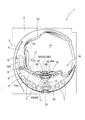
以下、本発明の一実施形態を図面に基づいて説明すると、実施形態のパチンコ遊技機(以下、単に遊技機と略す)1では、図1に示すように、遊技盤面2における外側レール3と内側レール4とで囲まれた遊技領域5を備え、遊技領域5には、その中央に、飾り枠体13に囲まれてセンター役物16が配設されている。センター役物16の後方には、液晶等で所定の図柄を表示する図柄表示装置14が配設されている。
Hereinafter, an embodiment of the present invention will be described with reference to the drawings. In a pachinko gaming machine (hereinafter simply referred to as a gaming machine) 1 according to an embodiment, as shown in FIG. A
遊技領域5の飾り枠体13の周囲には、図示しない釘、風車6、普通入賞口7、賞球の無い入賞口8、始動入賞口9、電動チューリップ10、大入賞口11、アウト口12等の公知の部材が配設されて、図示しないハンドルを操作し、遊技球を外側レール3と内側レール4との間から遊技領域5に打ち出せば、遊技球は、普通入賞口7、賞球の無い入賞口8、始動入賞口9、電動チューリップ10、大入賞口11、アウト口12のいずれかに入球する。そして、遊技球が、普通入賞口7や開放時の大入賞口11に入賞すれば、所定数の遊技球を獲得でき、入賞口8に入賞すれば、抽選により電動チューリップ10を所定時間若しくは所定回数開放させることとなる。また、遊技球が、始動入賞口9や開放時の電動チューリップ10に入賞すれば、抽選により、大当たり、中当たり、小当たり等の当たりや外れが決定され、当たりとなれば、大入賞口11を、その当たりに応じて開放時間、開放回数、入賞個数等を制限して、開放することとなる。これらの作動や遊技フローは、公知のものであり、遊技盤面2の背面側に配置された図示しないメイン制御基板が、入賞時のセンシングに基づき、各種の作動信号を出力し、そして、メイン制御基板からの当たりや外れ等の抽選結果に基づいて、図示しないサブ制御基板が、所定数の遊技球を払い出したり、所定のランプやスピーカ等を作動させつつ、所定の演出を図柄表示装置14に表示することとなる。
Around the
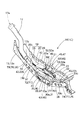
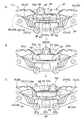
そして、飾り枠体13で囲まれた実施形態のセンター役物16は、図2に示すように、ステージ部19、ワープ通路17、入賞補助通路45、及び、リフト65を配設させて構成されている。ステージ部19は、飾り枠体13の下枠13a側に配置されて、遊技球Bを上面側でそれぞれ転動可能な上ステージ20と上ステージ20の下方に配置される下ステージ29との少なくとも二つのステージ20,29を有して構成されている。なお、実施形態では、図柄表示装置14に近い後部側に上ステージ20が配設され、下ステージ29が、前部側に配置されている。
The
ワープ通路17は、図1,2に示すように、ステージ部19への遊技球Bの入球口となるもので、飾り枠体13におけるステージ部19の上方側の左枠13b側で開口した入口17aから入る遊技球Bを、ステージ部19の下ステージ29の左縁側に転動可能に案内するように、配設されている。
As shown in FIGS. 1 and 2, the
そして、ステージ部19の上ステージ20は、図2,3に示すように、入賞補助通路45の流入側部位46を配設させた中央部21と、中央部21の左右両側に配設されて、上面側で遊技球Bを転動可能な左面部22及び右面部23と、を備えて構成されている。中央部21に設けられる入賞補助通路45の流入側部位46は、遊技球Bを流入させる流入口50を、左右方向に沿って往復移動するように、構成されている。左面部22と右面部23とは、それぞれ、中央部21から離れるに従って低くし、さらに、最も低い底部22b,23bから外縁22c,23c側にかけて、徐々に高くするように構成されている。また、左面部22と右面部23との中央部21側には、リフト65によって移送されても入賞補助通路45の流入口50に流入しなかった遊技球Bを、受け入れて、底部22b,23b側に転動させるエリア(隣接エリア)22a,23aが、配設されている。また、左面部22と右面部23との底部22b,23bは、下ステージ29側に遊技球Bを転動させる連通口43を構成する部位としている。なお、実施形態の場合、隣接エリア22a,23aは、リフト65を間にしたリフト65の左右両側に配置され、リフト65の後側には、後述する往復移動体47の横板部52,53の戻しエリア52a,53a、流入口50、及び、左右の区画壁51,51が配設され、さらに、これらの戻しエリア52a,53a、流入口50、及び、左右の区画壁51,51は、隣接エリア22a,23aの後半分側のエリアに、配設されている。
As shown in FIGS. 2 and 3, the
また、上ステージ20の後縁側には、図1,2に示すように、図柄表示装置14側との境界として、背面壁26が左右方向に沿って上方に突設され、背面壁26の左右方向の中央には、入賞補助通路45の流入側部位46に配設される往復移動体47の縦壁部48が、配設されている。往復移動体47は、後述するように、凹んだ凹部49を流入口50として、その流入口50を左右方向に沿って往復移動させるものである。
As shown in FIGS. 1 and 2, a
ステージ部19の下ステージ29は、図2,3に示すように、上面側で遊技球Bを転動可能として、左右方向の中央付近となる中央部30を低くし、中央部30の左右両側を高くするように構成され、左右の左縁34付近と右縁35付近とが、上ステージ20の左面部22と右面部23との外縁22c,23c付近と略面一の同じ曲面として、形成されている。また、下ステージ29の中央部30には、図5に示すように、後部側に配置されて遊技球Bをリフト65に案内可能な後下がりの案内面31と、前部側に配置される前下がりの傾斜面32と、が配設されている。案内面31は、リフト65における遊技球Bの受止エリア30aを構成することとなり、傾斜面32は、遊技球Bを下ステージ29の前縁から飾り枠体13(センター役物16)外の下方へ自由落下させて排出する排出路40を構成することとなる。また、下ステージ29の前縁側には、図2,3に示すように、傾斜面32が配設されたエリアを除いて、すなわち、排出路40のエリアを除いて、遊技球Bの前方側への落下を防止可能な突条37,38が、小さな突出量として、上方に突設されている。
As shown in FIGS. 2 and 3, the
なお、ワープ通路17の出口17bは、中央部30側に向いて、下ステージ29の左縁34付近に配設されている。
The
また、排出路40から落下する遊技球Bは、排出路40が左右方向に幅広に開口された状態としており、入賞補助通路45の流出口63から始動入賞口9に向けて落下するように流出される場合と相違して、殆ど、始動入賞口9に入賞せずに、落下していくこととなる。
Further, the game ball B falling from the
そして、遊技球Bが、図2,3に示すように、リフト65に受止保持されて上ステージ20の中央部21付近まで持ち上げられ、流入口50に流入しなかった場合には、その遊技球Bは、流入口50の左右両側の戻しエリア52a,53aを経て、左面部22と右面部23との隣接エリア22a,23aから底部22b,23b付近まで転動し、連通口43,43を経て、底部22b,23bから下ステージ29に転動し、そして、中央部30のリフト65付近まで転動し、排出路40から排出されなければ、受止エリア30aとしての案内面31に転動し、再度、リフト65で受止保持されて循環するようなループ動作する場合が生ずる。すなわち、左面部22や右面部23は、下ステージ29とともに、連通口43,43を利用して、遊技球Bをループ動作で戻すような戻しルート42を構成している。
2 and 3, when the game ball B is received and held by the
なお、上ステージ20と下ステージ29との間には、連通口43の部位を除いて、上ステージ20から下ステージ29側に遊技球Bが転動しないように、仕切壁27,27,28,28が、配設されている。仕切壁27,27は、下ステージ29の左縁34側と右縁35側とに配設され、仕切壁28,28は、隣接エリア22a,23a付近に配設されている。
In addition, between the
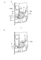
リフト65は、図3〜5に示すように、下ステージ29側の遊技球Bを、上ステージ20側における流入口50付近に移送可能に、移送動作を繰り返すものである。そして、リフト65は、下ステージ29側の遊技球Bを受け止めて保持し、かつ、上ステージ20側で遊技球Bを離脱可能な受止保持部67、を備えて構成されている。受止保持部67は、図4,5,8に示すように、下ステージ29側で受け止めた遊技球Bを略直上に移送させる構成としている。実施形態の場合、リフト65は、左右方向に沿う回転軸Cを有して回転する回転タイプとして、受止保持部67は、略円柱形状のロータ66の外周面に、遊技球Bを吸着可能な磁石68を配設させて構成されている。磁石68は、回転軸Cの軸方向に沿って、直線状に配置されるとともに、軸周り方向に120°ずつ離れて、計三個配設されている。なお、磁石68は、受止保持部67での配置を遊技者が認識できるように、ロータ66の外周面側に所定の色や模様等の意匠が施されて、配設されている。
As shown in FIGS. 3 to 5, the
ロータ66は、その軸方向に沿う左右方向の長さ寸法Lを、図4のBに示すように、流入口50の左右方向の開口寸法WHより広く設定されるとともに、下ステージ29側で受け止めた遊技球Bを、流入口50の左右方向の往復移動領域の上ステージ20側に移送可能に、設定されている。実施形態の場合、長さ寸法Lは、遊技球Bの直径寸法の4〜5倍程度(実施形態では約50mm)としている。なお、ロータ66の回転方向は、磁石68が、受止エリア30a側の前面側に向いた状態から、上方側に向き、さらに、流入口50内に入り込むような後方回転としている。
As shown in FIG. 4B, the
入賞補助通路45は、図1,2に示すように、流出側部位58に開口する流出口63を下ステージ29の下方に位置した始動入賞口9の上方で開口させ、また、上ステージ20の左右方向の中央付近に、流入側部位46の流入口50を開口させて構成されて、流入口50から流入した遊技球Bを、自重により、流出口63まで転動させ、流出口63から、始動入賞口9へ落下させるように流出可能として、始動入賞口9への入賞を補助するために配設されている。この入賞補助通路45は、図5のA〜Cに示すように、上ステージ20の左右方向の中央付近に配置された流入口50から、上ステージ20の背面、下方、さらに、下ステージ29の左右方向の中央の下方に位置する流出口63まで、前後方向に沿った略L字状の通路として構成されている。さらに、実施形態の流入口50は、左右方向に沿って往復移動する往復移動体47に配設されている。
As shown in FIGS. 1 and 2, the winning
往復移動体47は、図1,2に示すように、入賞補助通路45の流入側部位46に配設され、背面壁26の中央の凹部26aに配設される縦壁部48と、縦壁部48の左右両側の下縁付近から前方側に延びる二つの横板部52,53と、を備えて構成されている。そして、流入口50は、図2,4,5に示すように、縦壁部48の左右方向の中央から後方側に凹んで、横板部52,53間に連なる凹部49から構成されている。流入口50の左右方向の開口寸法WH(図4のB参照)は、遊技球Bの直径寸法より僅かに大きな寸法としている。さらに、流入口50の左右両縁には、横板部52,53から前方に延びる略長方形板状の区画壁51,51が配設されている。これらの区画壁51,51は、リフト65の軸心(回転軸C)の直上付近まで延ばすように配設されて、リフト65から移送されてくる遊技球Bが流入口50に流入する際に、区画壁51,51間でガイドされて、流入し易いように、構成されている。そして、区画壁51,51の外側における横板部52,53の上面側は、流入口50に流入しなかった遊技球Bを戻しルート42の隣接エリア22a,23aに転動させるように、戻しエリア52a,53aを構成している。戻しエリア52a,53aは、隣接エリア22a,23a側に遊技球Bを転動し易いように、流入口50から離れるに従って下がるような傾斜面として構成され、隣接エリア22a,23aの前後方向の略半分とした後縁側の下方に、侵入するように配設されている。
As shown in FIGS. 1 and 2, the reciprocating
また、この往復移動体47は、流入口50がリフト65の左右両端まで移動するように、左右方向に沿って往復移動可能に、配設されている。なお、詳しく言えば、リフト65の受止保持部67の左端や右端で受止保持する遊技球Bを流入口50に流入可能に、左右の区画壁51が、それぞれ、隣接エリア22a,23aに接触するまで、左右方向に往復移動する。
The
すなわち、この往復移動体47では、図2〜4に示すように、戻しエリア52a,53a上に移送された遊技球Bを隣接エリア22a,23a側に転動可能とするように、戻しエリア52a,53aは、流入口50から離れるに従って下がる斜面として、左右方向の往復移動時、横板部52,53の戻しエリア52a,53aの部位が、戻しエリア52a,53a上に移送された遊技球Bを隣接エリア22a,23a側に転動可能な状態を維持して、隣接エリア22a,23aの下方に、交互に、進入することとなる。そのため、戻しエリア52a,53aが交互に隣接エリア22a,23aの下方に侵入する必要があるため、この往復移動体47は、左右方向に沿う鉛直面で、かつ、正面視で流出口63付近を中心とするような回動運動によって、左右方向に沿って往復移動することとなる。そして、この往復移動体47は、リフト65を回転駆動させる駆動モータ等の駆動源からの駆動力を、図示しない歯車機構やカム・リンク機構等の動力伝達機構により伝動されて、回動運動を伴って左右方向に往復移動するように、飾り枠体13内で支持されている。
That is, in the
さらに、往復移動体47は、図5,8に示すように、左右の区画壁51の下端側に、前方へ湾曲して延びるような下縁部54を備えている。そして、下縁部54は、縦壁部48の凹部49の下縁側と連なって、筒状体56を結合させる略円筒状の連結筒部55を形成している。
Further, as shown in FIGS. 5 and 8, the reciprocating
筒状体56は、図5,7,8に示すように、上端側を連結筒部55に結合させ、下端側を入賞補助通路45の流出側部位58の略円筒状の連結筒部58aに結合させている。この筒状体56は、遊技球Bを流入側部位46から、移動せずに固定されて配設されている流出側部位58まで案内するものであり、往復移動体47の左右方向の往復移動に追従する可撓性を有した合成樹脂やゴム等からなる蛇腹管、あるいは、合成樹脂、ゴム、金属等からなるコイルスプリング等の筒体から形成されている。実施形態の場合、遊技球Bの直径寸法より僅かに大きな内径寸法を有した合成樹脂製の蛇腹管が使用されている。
As shown in FIGS. 5, 7, and 8, the
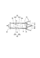
入賞補助通路45の流出側部位58は、図5に示すように、下ステージ29の下方に前後方向に沿って貫通するとともに、後端の連結筒部58aから前下がりに傾斜するように配設され、前端に開口させた流出口63を始動入賞口9の直上に配置させている。そして、流出口63の近傍には、流出口63側に向かう遊技球Bに対して、少なくとも下方と左右両側とから接触し、流出口63から始動入賞口9に向かう遊技球Bの流出方向を安定させる案内部59が、配設されている。実施形態の案内部59は、略四角筒形状として、上方側の天井壁部60と、下面側の底壁部61と、左右の側壁部62,62と、を備えて構成され、左右の側壁部62,62が、前方に向かうに連れて左右方向の幅寸法を狭めるテーパ面部62a,62aと、前後方向で相互に平行となるストレート部62b,62bと、を配設させて構成されている(図7参照)。ストレート部62b,62bの左右方向の開口寸法WEは、遊技球Bの直径寸法より僅かに大きな寸法としている。この案内部59では、連結筒部58aから前方に向かう遊技球Bが、テーパ面部62a,62aからストレート部62b,62bの相互の間を通過する際、減速されつつ左右のブレを抑制されて、前方に向かう安定した直進性を付与されるとともに、入賞確率をより高めた安定した速度で、流出口63から始動入賞口9に向けて流出(落下)させることができる。
As shown in FIG. 5, the
なお、実施形態の場合、往復移動体47が左右方向に一往復する際、リフト65が一回転するように、構成されている。
In the case of the embodiment, the
実施形態の遊技機1の作動を説明すれば、電源オンとともに、図示しない駆動源と動力伝達機構とによって、往復移動体47が左右方向に沿って往復移動するとともに、リフト65が後方回転することとなる。そして、遊技時、ワープ通路17の入口17aに遊技球Bが入球されれば、遊技球Bは、出口17bから下ステージ29に転動する(図3,4参照)。
The operation of the
この転動時、遊技球Bが、リフト65の受止保持部67に受止保持されれば、上ステージ20側に移送される。その際、入賞補助通路45の流入口50が、左右方向に沿って往復移動しており、また、リフト65の受止保持部67が、左右方向の長さ寸法Lを流入口50の左右方向の開口寸法WHより広く設定され(図4のB参照)、かつ、下ステージ29側で受け止めた遊技球Bを、流入口50の左右方向の往復移動領域の上ステージ20側に移送可能に、配設されている。そのため、リフト65の受止保持部67に保持された遊技球Bが、上ステージ20側に移送される際、確実に流入口50に流入するわけでなく、流入口50に流入する(図5参照)か、あるいは、否か(図6参照)として、遊技者にハラハラドキドキさせることとなる。そして、リフト65で移送された遊技球Bが流入口50に流入しなくとも、流入口50が、移送時に流入口50に流入しなかった遊技球Bを上ステージ20の戻しルート42のエリアである戻しエリア52a,53aに転動可能として、左右方向に沿って往復移動するように、配設されており、流入口50への流入を外した遊技球Bは、遊技を完了させることなく、戻しルート42の戻しエリア52a,53aや隣接エリア22a,23b、さらに、左面部22,23の底部22b,23b、連通口43,43を経て、下ステージ29側に転動できる。そして、排出路40からセンター役物16(飾り枠体13)外に排出されずに、下ステージ29側のリフト65の受止エリア30aに配置されれば、再度、流入口50に流入可能に、リフト65によって移送される。すなわち、リフト65で移送された遊技球Bが左右に往復移動する流入口50に流入しなくとも、流入口50への流入を外した遊技球Bは、排出路40からセンター役物16外に排出される場合を除いて、流入口50に流入されるまで、上記の動作がリプレイされることとなって、遊技の趣向性を向上させることができる。
During this rolling, if the game ball B is received and held by the receiving and holding
したがって、実施形態の遊技機1では、左右に往復移動する流入口50と、その移動する流入口50の周囲に、遊技球Bが、流入口50に流入しなくとも、その遊技球Bをリプレイできるように下ステージ29側に転動させる戻しルート42の戻しエリア52a,53aと、を配設させているため、遊技球Bがリフト65によって流入口50付近に移送される際の遊技の趣向性を、一層、向上させることができる。
Therefore, in the
そして、実施形態の遊技機1では、入賞補助通路45の内周に、流出口63側に向かう遊技球Bに対して、少なくとも下方と左右両側とから接触し、流出口63から始動入賞口9に向かう遊技球Bの流出方向を安定させる案内部59を、配設させている(図7参照)。そのため、入賞補助通路45の流入口50に流入した遊技球Bを、始動入賞口9への入賞確率を高めて、流出口63から始動入賞口9へ向けて流出させることができる。すなわち、実施形態の遊技機1では、左右に往復移動する流入口50に流入した遊技球Bは、流入口50への流入時における流入口50自体の左右方向への往復移動により、入賞補助通路45を通過する際、左右方向へのブレを伴って、流出口63側に転動し易い。しかし、実施形態では、案内部59の底壁部61、及び、左右の側壁部62のテーパ面部62a相互やストレート部62b相互が、流出口63側に向かう遊技球Bに対して、少なくとも下方と左右両側とから接触することにより、減速させつつ、遊技球Bの左右方向へのブレを抑制できて、入賞し易い軌跡となるような速度の自由落下とし、かつ、流出口63から始動入賞口9に向かう遊技球Bの流出方向を、前向きの直線状として、安定させることから、入賞確率を高めて、遊技球Bを流出口63から始動入賞口9へ向けて流出させることができる。
In the
なお、案内部としては、図9に示す案内部59Aのように、ある程度の形状保持性を有して弾性変形可能なゴムや合成樹脂からなるリップ形状(ヒレ形状)の弾性支持部62c,62cを左右の側壁部62,62に設けてもよい。このような案内部59Aでは、弾性支持部62c,62cが、底壁部61を転動する遊技球Bの前面に左右で均等に撓みつつ接触するように配設されており、遊技球Bとの接触時、前方側への直進性を付与しつつ遊技球Bを減速させることができる。
As the guide portion, as in the
さらに、実施形態では、入賞補助通路45に、遊技球Bを案内部59側に案内可能に流入口50側に連通し、流入口50の左右方向の移動に追従可能な可撓性を有した筒状体56を配設させている(図5,7,8参照)。そのため、実施形態では、流入口50から流入した遊技球Bが、案内部59に到達する前の筒状体56を通過する際に、転動する軌跡を、大きな曲率で屈曲させることなく(入賞補助通路45の内周壁に直線的に反射させることなく)、左右のぶれを抑制できるように曲線状として、通過させることができ、案内部59に到達する前に、極力、遊技球Bの流出方向を直線的に安定させることができて、案内部59を経て、一層、入賞確率を高めて、遊技球Bを流出口63から始動入賞口9へ向けて流出させることができる。
Furthermore, in the embodiment, the game ball B is communicated with the winning
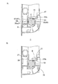
また、実施形態では、リフト65の受止保持部67が、遊技球Bを吸着する磁石68を利用して、遊技球Bを受け止めた位置の略直上の上ステージ20側に移送できるように、構成されている(図4,5,6参照)。そのため、実施形態では、受止保持部67で受け止めて上ステージ20側に移送する際、左右に大きく転動せずに、受け止めた位置の略直上に遊技球Bを移送できることから、左右に移動する流入口50の開口面50a(実施形態の場合には、リフト65の軸心(回転軸C)の直上付近に配設された区画壁51,51の前端相互の間の面となる)に対して、直交する方向で遊技球Bを移送できて、流入口50に遊技球Bを流入させ易くなる。
Further, in the embodiment, the
特に、実施形態の場合には、磁石68が、リフト65の回転軸Cに沿うように、直線状に配設されており、受止保持部67における磁石68を設けたリフト65の軸方向に沿う全域の任意の位置で、遊技球Bを吸着して直上に移送できる。そのため、吸着された遊技球Bのリフト65の回転軸Cの軸方向に沿う位置が、吸着された遊技球B毎に微妙に異なることとなり、遊技球Bの吸着された位置の直上に流入口50が配置されるか否か、吸着された遊技球B毎に、ハラハラドキドキできて、遊技の趣向性を向上させることができる。なお、実施形態では、棒状の磁石68を使用して、回転軸Cに沿って直線状に磁石68を配置させた場合を示したが、円板状等の多数の磁石を利用して、これらの磁石を、回転軸Cに沿って直線状にロータ66の外周面に配設させてもよい。
Particularly, in the case of the embodiment, the
なお、上記の点を考慮しなければ、図10〜11に示す遊技機1Bのリフト65Bのように、磁石69,70を、リフト65Bの回転軸Cに沿う方向で、回転軸Cの軸周り方向にずらして、配設してもよい。図例の場合には、リフト65の受止保持部67の左側部67aと右側部67bとのそれぞれの軸方向の中央付近に、軸周り方向に120°ずつずらして、円板状の磁石69を3個ずつ配設し、受止保持部67の中央部67cの軸方向の中央付近に、軸周り方向に180°ずらして、円板状の磁石70を2個配設させている。そして、左側部67aと右側部67bとの各磁石69は、リフト65Bの軸周り方向に一致する角度位置に配設されているものの、中央部67cの各磁石70は、一つの磁石70が一つの磁石69とリフト65Bの軸周り方向に一致する角度位置に配設されている。このようなリフト65Bでは、実施形態のリフト65のように、受止保持部67における磁石68を設けたリフト65の軸方向に沿う全域の任意の位置で遊技球Bを吸着できず、磁石69,70の配置位置で遊技球Bを吸着して、上ステージ20側に移送することとなる。そして、このリフト65Bは、リフト65と相違して、逆に、受止保持部67の遊技球Bの吸着される箇所が磁石69,70の位置となるため、遊技球Bの吸着された位置の直上に流入口50が配置されるか否か、予測し易くなる。なお、各磁石69,70は、数や、リフト65Bの軸周り方向での配置位置を、適宜、変更してもよい。
If the above points are not taken into consideration, the
なお、実施形態では、仕切壁27,28をステージ部19に固定したものを示したが、図12〜17に示す遊技機1Cのように、リフト65の受止保持部67への遊技球Bの受止位置を変更させるように、仕切壁28と近似した可動片72,77を移動させる構成としてもよい。
In the embodiment, the
この遊技機1Cでは、下ステージ29側におけるリフト65の前側に、可動片72,77が配設されている。各可動片72,77は、図14,15に示すように、左右方向に沿って往復移動し、下ステージ29を転動する遊技球Bに接触して、遊技球Bのリフト65の受止保持部67に受止保持される部位を変更させるものである。具体的には、可動片72,77は、左右方向に沿って、相互に接近しかつ離隔するように往復移動し、相互の接近時、図14のAや図15のAに示すように、受止保持部67の左右両側の部位(左側部67aと右側部67b)の前側を覆って、受止保持部67の左右方向の中央部67cの前側を開け、相互の離隔時に、図14のCや図15のBに示すように、受止保持部67の前側の全域を開けるように、配設されている。
In this
なお、左右の可動片72,77は、それぞれ、仕切壁27,27に近似した装飾体74,79を一体的に連結させた可動体71,76に配設されて、装飾体74,79とともに、雲形状の意匠を施された略半円板状として、上ステージ20と下ステージ29との間の左右に延びたスリット19a,19b,19cから上方に突出している(図12,13参照)。各可動体71,76は、それぞれ、可動片72,77と装飾体74,79とを連結杆部73,78(図16のA、図17のA参照)によって連結して構成されている。連結杆部73は、リフト65の左方側の可動片72と右面部23側の連通口43付近に配置される装飾体74とを、下ステージ29の下方側で連結している。また、連結杆部78は、リフト65の右方側の可動片77と左面部22側の連通口43付近に配置される装飾体79とを、下ステージ29の下方側で連結している。
The left and right
これらの可動体71,76は、相互に略左右対称形に形成され、図示しない回動カムの回転により、左右方向に沿って往復移動することとなる。
These
ちなみに、可動体71の往復移動時には、図15のA,Bに示すように、可動片72が、左側部67aの前側を覆いかつ中央部67cの前側を隠さない状態から、左側部67aの前側を覆わない状態まで、左方側に移動するように、往復移動し、その際、装飾体74は、左端側に移動した際、右面部23側の連通口43の前側を塞ぎ、右端側に移動した際、その連通口43を開口することとなる。なお、装飾体74が右面部23側の連通口43の前側を閉口している際、実施形態の場合には、右側の可動片77が右端側に移動しており、右面部23側の連通口43の前側が、装飾体74と可動片77の右縁付近とによって、二枚重ねで塞がれることとなる。
Incidentally, when the
また、可動体76の往復移動時には、図15のA,Bに示すように、可動片77が、右側部67bの前側を覆いかつ中央部67cの前側を隠さない状態から、右側部67bの前側を覆わない状態まで、右方側に移動するように、往復移動し、その際、装飾体79は、右端側に移動した際、左面部22側の連通口43の前側を塞ぎ、左端側に移動した際、その連通口43を開口することとなる。なお、装飾体79が左面部22側の連通口43の前側を閉口している際、実施形態の場合には、左側の可動片72が左端側に移動しており、左面部22側の連通口43の前側が、装飾体79と可動片72の左縁付近とによって、二枚重ねで塞がれることとなる。
Further, when the
これらの可動体71,76は、それぞれ、図示しない回転カムが歯車機構やリンク機構等の動力伝達機構を利用して、往復移動体47を往復移動させたり、リフト65を回転駆動させる駆動モータ等の駆動源と機械的に連結されており、駆動源の作動時、往復移動体47や可動体71,76の左右方向に沿う往復移動とリフト65との回転とが、連動して動作されるように構成されている。
Each of these
ちなみに、この遊技機1Cでは、往復移動体47が左右方向に一往復する際、可動体71,76も左右方向に一往復し、また、リフト65が一回転するように、構成されている。但し、この往復移動体47と可動体71,76との移動するタイミングや周期は適宜変更してもよい。
Incidentally, in this
この遊技機1Cでは、下ステージ29側のリフト65における受止保持部67の前側に、左右方向に沿って往復移動するように配設されて、遊技球Bのリフト65の受止保持部67に受止保持される部位を変更させるように、下ステージ29を転動する遊技球Bに接触する可動片72,77が、配設されている。そのため、遊技球Bが下ステージ29を転動して受止保持部67の磁石68で受止保持される際、図16に示すように、遊技球Bが流入口50に流入したり、あるいは、図17に示すように、遊技球Bが戻しルート42に転動される戻しエリア53aに移送される場合が生ずる。そして、この遊技機1Cでは、流入口50の左右の往復移動のタイミングにより、受止保持部67のどの位置で受け止められれば、流入口50に流入するかが予測されていても、その遊技球Bの受止保持部位での実際の受止位置が、遊技球Bの可動片72,77との接触により、流入口50に流入し易い位置、あるいは、流入口50に流入し難い位置に、変更され、実際の移送動作が開始されるまで、どの位置で、受止保持されるかが予測し難くなって、遊技の趣向性を向上させることができる。
In this
なお、この遊技機1Cでも、図10に示すリフト65Bを使用してもよい。この場合、遊技球Bの吸着される位置が、可動片72,77で前側を覆われるか、あるいは、前側を覆われないかによって、リフト65Bの左側部67aや右側部67bの磁石69の位置となるか、あるいは、中央部67cの磁石70の位置となるか、大きくずれるため、実際の移送動作が開始されるまで、どの位置で、受止保持されるか予測し難くなって、遊技の趣向性を向上させることができる。
In this
また、図12〜17に示す遊技機1Cでは、ステージ部19上で突出するとともに可動片72,77に連動して左右に往復移動する装飾体74,79が、可動片72,77に連結させて配設されている。実施形態の装飾体74,79は、可動片72,77とともに、雲型等の意匠が施されている。そのため、遊技機1Cでは、可動片72,77と装飾体74,79との左右方向に沿う往復移動により、往復移動体47の左右方向の往復移動とともに、ステージ部19での演出効果を一層高めることもできる。
In addition, in the
また、既述の遊技機1,1B,1Cでは、遊技球Bを受止保持するリフトとして、左右方向に沿う回転軸Cを有して回転し、磁石68,69,70を受止保持部67に利用した回転タイプのリフト(回転リフト)65,65Bを例示したが、遊技球Bを略直上の移送可能な他の回転タイプのリフトとしては、受止保持部を、遊技球を保持可能なバケットや羽根から構成したものでもよい。但し、リフト65,65Bのように、受止保持部67が、略円柱形状として、外周面に、遊技球Bを吸着可能な磁石68,69,70を配設させて構成されれば、受止保持部を、遊技球を保持可能なバケットや羽根から構成する場合に比べて、直径寸法をコンパクトに構成でき、ステージ部19の前後方向の幅寸法に制限のある場合に好適となる。
Further, in the above-described
また、遊技球を受止保持するリフトとしては、上面側を、下ステージ29側で遊技球Bを受け止めて上ステージ20側に上昇させ、流入口50や隣接エリア22a,23aに転動させるような受止保持部として、上下動を繰り返す上下往復移動タイプとしてもよい。
In addition, as a lift for receiving and holding the game ball, the upper surface side receives the game ball B on the
また、実施形態では、案内部59や筒状体56を設けた場合を示したが、案内部59のテーパ面部62aやストレート部62bを設けずに構成したり、あるいは、筒状体56を設けずに構成してもよい。この場合の構成としては、図18,19に示す遊技機1Dに示すように、連結筒部55,58aを設けずに、流入口50Dから流出側部位58まで連通するように、上ステージ20と下ステージ29との下方に設ける内部空間を入賞補助通路45として構成してもよい。このような構成では、リフト65に吸着されて流入口50Dに流入してきた遊技球Bは、横板部57や重量で、リフト65から離脱させて、流出側部位58側に落下させ、流出口63から始動入賞口9に向けて流出させることとなる。
In the embodiment, the
さらに、上記の遊技機1Dのように、入賞補助通路45の左右方向に沿って往復移動する流入口50Dの構成として、上下に往復移動する往復移動体47Dとしての縦壁部48Dに、前後に貫通するとともに斜め方向に延びる貫通穴48aを設け、上ステージ20の中央部21におけるリフト65の上後側に、後下がりで左右に下がる横板部57を設け、横板部57の上面側を案内面兼用の戻しエリア57aとして構成してもよい。貫通穴48aの左右方向の開口寸法は、一個分の遊技球Bを挿通可能な寸法に設定されている。この遊技機1Dでは、往復移動体47Dの縦壁部48Dが、横板部57の後縁57b側で上下に往復移動し、貫通穴48aにおける横板部57の後縁57b付近に位置する部位が、実質的に左右方向に往復移動する流入口50Dとなる。すなわち、後縁57b付近の流入口50Dは、図19のCに示すように、例えば、縦壁部48Dが最上昇位置に配置されれば、流入口50Dがリフト65の左側部67a側に配置され、図19のAに示すように、縦壁部48Dが最下降位置に配置されれば、流入口50Dがリフト65の右側部67b側に配置されて、縦壁部48Dの上下往復移動によって、実質的に遊技球Bを入賞補助通路45に流入させる流入口50Dが、左右方向に往復移動することとなり、このように流入口50Dを構成してもよい。
Further, as in the
なお、実施形態では、デジパチタイプの遊技機1について説明したが、デジパチタイプ以外のセンター役物のあるハネモノタイプのパチンコ遊技機等に、本発明を適用してもよい。
In the embodiment, the digipachi
また、実施形態では、ステージ部19への遊技球Bの入球が、パイプ状のワープ通路17からなる入球口を使用して行われる場合を例示したが、単に、飾り枠体13の内外を貫通する入球口を利用して、ステージ部19上に遊技球Bを入球させるように構成してもよい。
Further, in the embodiment, the case where the game ball B enters the
さらに、リフト65,65B、あるいは、ステージ部19の中央部21,30付近は、内部を通過する遊技球Bを視認できるように、ある程度の透明度を有した合成樹脂材料等からなる透明体(若しくは半透明体)から形成してもよい。
Further, the
1,1B,1C,1D…(パチンコ)遊技機、
9…(始動)入賞口、
16…センター役物、
19…ステージ部、
20…上ステージ、
29…下ステージ、
30a…受止エリア、
40…排出路、
42…戻しルート、
43…連通口、
45…入賞補助通路、
50,50D…流入口、
63…流出口、
65,65B…リフト、
67…受止保持部、
68,69,70…磁石、
72,77…可動片、
B…遊技球。
1, 1B, 1C, 1D ... (Pachinko) gaming machine,
9 ... (Startup)
16 ... Center character,
19 ... Stage part,
20 ... Upper stage,
29 ... the lower stage,
30a ... receiving area,
40 ... discharge path,
42 ... Return route,
43. Communication port,
45. Prize winning aisle,
50, 50D ... Inlet,
63 ... Outlet,
65, 65B ... lift,
67 ... receiving holding part,
68, 69, 70 ... magnets,
72, 77 ... movable piece,
B ... A game ball.
Claims (8)
遊技球をそれぞれ転動可能な上ステージと該上ステージの下方に配置される下ステージとの少なくとも二つのステージを有するステージ部と、
遊技球を、前記上ステージに開口させた流入口から流入させ、流出口から入賞口へ向けて流出可能とする入賞補助通路と、
前記下ステージ側の遊技球を受け止めて前記上ステージ側に移送可能な受止保持部を有して、遊技球の移送動作を繰り返すリフトと、
前記流入口に流入しなかった遊技球を、前記上ステージから前記下ステージにおける前記リフトの遊技球の受止エリアまで転動させて戻し可能な戻しルートと、
前記下ステージに配置されて、前記下ステージの前縁から遊技球をセンター役物外へ排出可能な排出路と、
前記ステージ部に遊技球を入球させる入球口と、
を備えて構成されるパチンコ遊技機であって、
前記流入口が、前記リフトの受止保持部によって移送される遊技球を流入可能に、前記上ステージ側における前記リフトの後側に配設されるとともに、移送時に前記流入口に流入しなかった遊技球を前記上ステージの戻しルートのエリアに転動可能として、左右方向に沿って往復移動するように、配設され、
前記リフトの受止保持部が、左右方向の長さを前記流入口の左右方向の開口寸法より広く設定されるとともに、前記下ステージ側で受け止めた遊技球を、前記流入口の左右方向の往復移動領域の前記上ステージ側に移送可能に、配設されていることを特徴とするパチンコ遊技機。 Center role is
A stage unit having at least two stages of an upper stage capable of rolling the game balls and a lower stage disposed below the upper stage;
A winning auxiliary passage that allows a game ball to flow in from the inflow opening opened in the upper stage and to flow out from the outflow toward the winning opening,
A lift that receives the game ball on the lower stage side and has a receiving holding part that can be transferred to the upper stage side, and repeats the transfer operation of the game ball; and
A return route that allows the game balls that have not flowed into the inflow port to roll back from the upper stage to the receiving area of the lift game balls in the lower stage; and
A discharge path disposed on the lower stage and capable of discharging the game ball from the front edge of the lower stage to the outside of the center role;
A entrance for entering a game ball into the stage part,
A pachinko machine configured with
The inflow port is disposed on the rear side of the lift on the upper stage side so that a game ball transferred by the lift receiving holding portion can flow in, and does not flow into the inflow port at the time of transfer. The game ball can be rolled to the return route area of the upper stage, and is arranged to reciprocate along the left-right direction.
The lift receiving / holding portion is set to have a length in the left-right direction wider than the opening size in the left-right direction of the inflow port, and the game ball received on the lower stage side is reciprocated in the left-right direction of the inflow port. A pachinko gaming machine, wherein the pachinko gaming machine is arranged so as to be transportable to the upper stage side of a moving area.
前記リフトの受止保持部が、略円柱形状として、外周面に、遊技球を吸着可能な磁石を配設させて構成されていることを特徴とする請求項4に記載のパチンコ遊技機。 As a configuration in which the lift rotates with a rotation axis along the left-right direction,
The pachinko gaming machine according to claim 4, wherein the lift receiving and holding portion has a substantially cylindrical shape and is configured such that a magnet capable of attracting a game ball is disposed on an outer peripheral surface thereof.
Priority Applications (1)
| Application Number | Priority Date | Filing Date | Title |
|---|---|---|---|
| JP2008203554A JP5379423B2 (en) | 2008-08-06 | 2008-08-06 | Pachinko machine |
Applications Claiming Priority (1)
| Application Number | Priority Date | Filing Date | Title |
|---|---|---|---|
| JP2008203554A JP5379423B2 (en) | 2008-08-06 | 2008-08-06 | Pachinko machine |
Publications (2)
| Publication Number | Publication Date |
|---|---|
| JP2010035884A true JP2010035884A (en) | 2010-02-18 |
| JP5379423B2 JP5379423B2 (en) | 2013-12-25 |
Family
ID=42009013
Family Applications (1)
| Application Number | Title | Priority Date | Filing Date |
|---|---|---|---|
| JP2008203554A Expired - Fee Related JP5379423B2 (en) | 2008-08-06 | 2008-08-06 | Pachinko machine |
Country Status (1)
| Country | Link |
|---|---|
| JP (1) | JP5379423B2 (en) |
Citations (5)
| Publication number | Priority date | Publication date | Assignee | Title |
|---|---|---|---|---|
| JP2003181113A (en) * | 2001-12-17 | 2003-07-02 | Takeya Co Ltd | Pachinko ball collector |
| JP2004097800A (en) * | 2002-07-17 | 2004-04-02 | Daiichi Shokai Co Ltd | Game machine |
| JP2004313348A (en) * | 2003-04-14 | 2004-11-11 | Hideki Iwatani | Pachinko ball ejecting device from ball tray |
| JP2006223731A (en) * | 2005-02-21 | 2006-08-31 | Olympia:Kk | Game ball distributing device |
| JP2008079681A (en) * | 2006-09-26 | 2008-04-10 | Sophia Co Ltd | Game machine |
-
2008
- 2008-08-06 JP JP2008203554A patent/JP5379423B2/en not_active Expired - Fee Related
Patent Citations (5)
| Publication number | Priority date | Publication date | Assignee | Title |
|---|---|---|---|---|
| JP2003181113A (en) * | 2001-12-17 | 2003-07-02 | Takeya Co Ltd | Pachinko ball collector |
| JP2004097800A (en) * | 2002-07-17 | 2004-04-02 | Daiichi Shokai Co Ltd | Game machine |
| JP2004313348A (en) * | 2003-04-14 | 2004-11-11 | Hideki Iwatani | Pachinko ball ejecting device from ball tray |
| JP2006223731A (en) * | 2005-02-21 | 2006-08-31 | Olympia:Kk | Game ball distributing device |
| JP2008079681A (en) * | 2006-09-26 | 2008-04-10 | Sophia Co Ltd | Game machine |
Also Published As
| Publication number | Publication date |
|---|---|
| JP5379423B2 (en) | 2013-12-25 |
Similar Documents
| Publication | Publication Date | Title |
|---|---|---|
| JP4702736B2 (en) | Game machine | |
| JP4854446B2 (en) | Display device for gaming machine | |
| JP5379423B2 (en) | Pachinko machine | |
| JP2009066353A (en) | Pinball game machine | |
| JP5113650B2 (en) | Pachinko machine | |
| JPH03195575A (en) | Pachinko (japanese pinball) machine | |
| JP2006000514A (en) | Game machine | |
| JP2010029519A (en) | Jackpot pocket opening/closing door opening/closing device of game machine | |
| JP5465490B2 (en) | Stage structure | |
| JP2010017313A (en) | Pachinko game machine | |
| JP2006115899A (en) | Game machine | |
| JP6826709B2 (en) | Game machine | |
| JP5538730B2 (en) | Pachinko machine | |
| JP2009066352A (en) | Pinball game machine | |
| JP4754810B2 (en) | Game machine | |
| JP5642926B2 (en) | Big prize opening device | |
| JP2006288702A (en) | Game machine | |
| JP5113649B2 (en) | Pachinko machine | |
| JP4603338B2 (en) | Game machine | |
| JP5469831B2 (en) | Game machine | |
| JP2005237843A (en) | Pachinko game machine | |
| JP2006025862A (en) | Game machine | |
| JP4342465B2 (en) | Game machine | |
| JP2007252537A (en) | Game machine | |
| JP4754808B2 (en) | Game machine |
Legal Events
| Date | Code | Title | Description |
|---|---|---|---|
| A621 | Written request for application examination |
Free format text: JAPANESE INTERMEDIATE CODE: A621 Effective date: 20110420 |
|
| A977 | Report on retrieval |
Free format text: JAPANESE INTERMEDIATE CODE: A971007 Effective date: 20120912 |
|
| A131 | Notification of reasons for refusal |
Free format text: JAPANESE INTERMEDIATE CODE: A131 Effective date: 20120918 |
|
| A521 | Written amendment |
Free format text: JAPANESE INTERMEDIATE CODE: A523 Effective date: 20121109 |
|
| A02 | Decision of refusal |
Free format text: JAPANESE INTERMEDIATE CODE: A02 Effective date: 20130423 |
|
| A521 | Written amendment |
Free format text: JAPANESE INTERMEDIATE CODE: A523 Effective date: 20130717 |
|
| A911 | Transfer of reconsideration by examiner before appeal (zenchi) |
Free format text: JAPANESE INTERMEDIATE CODE: A911 Effective date: 20130725 |
|
| TRDD | Decision of grant or rejection written | ||
| A01 | Written decision to grant a patent or to grant a registration (utility model) |
Free format text: JAPANESE INTERMEDIATE CODE: A01 Effective date: 20130910 |
|
| A61 | First payment of annual fees (during grant procedure) |
Free format text: JAPANESE INTERMEDIATE CODE: A61 Effective date: 20130927 |
|
| R150 | Certificate of patent or registration of utility model |
Ref document number: 5379423 Country of ref document: JP Free format text: JAPANESE INTERMEDIATE CODE: R150 Free format text: JAPANESE INTERMEDIATE CODE: R150 |
|
| R250 | Receipt of annual fees |
Free format text: JAPANESE INTERMEDIATE CODE: R250 |
|
| LAPS | Cancellation because of no payment of annual fees |