JP2010034003A - Fixture and electric connector using the fixture - Google Patents
Fixture and electric connector using the fixture Download PDFInfo
- Publication number
- JP2010034003A JP2010034003A JP2008197650A JP2008197650A JP2010034003A JP 2010034003 A JP2010034003 A JP 2010034003A JP 2008197650 A JP2008197650 A JP 2008197650A JP 2008197650 A JP2008197650 A JP 2008197650A JP 2010034003 A JP2010034003 A JP 2010034003A
- Authority
- JP
- Japan
- Prior art keywords
- fixture
- shell
- contact
- fitting
- electrical connector
- Prior art date
- Legal status (The legal status is an assumption and is not a legal conclusion. Google has not performed a legal analysis and makes no representation as to the accuracy of the status listed.)
- Granted
Links
- 239000000758 substrate Substances 0.000 claims abstract description 28
- 238000003825 pressing Methods 0.000 claims abstract description 12
- 239000004020 conductor Substances 0.000 claims abstract description 9
- 238000000465 moulding Methods 0.000 claims abstract description 4
- 238000012423 maintenance Methods 0.000 abstract 1
- 230000013011 mating Effects 0.000 description 19
- 238000003780 insertion Methods 0.000 description 11
- 230000037431 insertion Effects 0.000 description 11
- 238000000034 method Methods 0.000 description 5
- XEEYBQQBJWHFJM-UHFFFAOYSA-N Iron Chemical compound [Fe] XEEYBQQBJWHFJM-UHFFFAOYSA-N 0.000 description 4
- 239000000463 material Substances 0.000 description 4
- 238000005476 soldering Methods 0.000 description 4
- 229910001369 Brass Inorganic materials 0.000 description 3
- 229910000906 Bronze Inorganic materials 0.000 description 3
- OAICVXFJPJFONN-UHFFFAOYSA-N Phosphorus Chemical compound [P] OAICVXFJPJFONN-UHFFFAOYSA-N 0.000 description 3
- DMFGNRRURHSENX-UHFFFAOYSA-N beryllium copper Chemical compound [Be].[Cu] DMFGNRRURHSENX-UHFFFAOYSA-N 0.000 description 3
- 239000010951 brass Substances 0.000 description 3
- 239000010974 bronze Substances 0.000 description 3
- KUNSUQLRTQLHQQ-UHFFFAOYSA-N copper tin Chemical compound [Cu].[Sn] KUNSUQLRTQLHQQ-UHFFFAOYSA-N 0.000 description 3
- 238000005520 cutting process Methods 0.000 description 3
- 239000002184 metal Substances 0.000 description 3
- 229910052751 metal Inorganic materials 0.000 description 3
- 238000003466 welding Methods 0.000 description 3
- 229920000106 Liquid crystal polymer Polymers 0.000 description 2
- 239000004977 Liquid-crystal polymers (LCPs) Substances 0.000 description 2
- 230000001965 increasing effect Effects 0.000 description 2
- 239000012212 insulator Substances 0.000 description 2
- 229910052742 iron Inorganic materials 0.000 description 2
- 229920001707 polybutylene terephthalate Polymers 0.000 description 2
- 229910000881 Cu alloy Inorganic materials 0.000 description 1
- 239000004952 Polyamide Substances 0.000 description 1
- UCKMPCXJQFINFW-UHFFFAOYSA-N Sulphide Chemical compound [S-2] UCKMPCXJQFINFW-UHFFFAOYSA-N 0.000 description 1
- 230000008602 contraction Effects 0.000 description 1
- 238000010586 diagram Methods 0.000 description 1
- 238000006073 displacement reaction Methods 0.000 description 1
- 230000000694 effects Effects 0.000 description 1
- 230000001939 inductive effect Effects 0.000 description 1
- 238000001746 injection moulding Methods 0.000 description 1
- 238000003754 machining Methods 0.000 description 1
- 239000004033 plastic Substances 0.000 description 1
- 229920006128 poly(nonamethylene terephthalamide) Polymers 0.000 description 1
- 229920002647 polyamide Polymers 0.000 description 1
- -1 polybutylene terephthalate Polymers 0.000 description 1
- 229920000515 polycarbonate Polymers 0.000 description 1
- 239000004417 polycarbonate Substances 0.000 description 1
- 229910000679 solder Inorganic materials 0.000 description 1
- 229920002994 synthetic fiber Polymers 0.000 description 1
Images


Classifications
-
- H—ELECTRICITY
- H01—ELECTRIC ELEMENTS
- H01R—ELECTRICALLY-CONDUCTIVE CONNECTIONS; STRUCTURAL ASSOCIATIONS OF A PLURALITY OF MUTUALLY-INSULATED ELECTRICAL CONNECTING ELEMENTS; COUPLING DEVICES; CURRENT COLLECTORS
- H01R13/00—Details of coupling devices of the kinds covered by groups H01R12/70 or H01R24/00 - H01R33/00
- H01R13/62—Means for facilitating engagement or disengagement of coupling parts or for holding them in engagement
- H01R13/639—Additional means for holding or locking coupling parts together, after engagement, e.g. separate keylock, retainer strap
-
- H—ELECTRICITY
- H01—ELECTRIC ELEMENTS
- H01R—ELECTRICALLY-CONDUCTIVE CONNECTIONS; STRUCTURAL ASSOCIATIONS OF A PLURALITY OF MUTUALLY-INSULATED ELECTRICAL CONNECTING ELEMENTS; COUPLING DEVICES; CURRENT COLLECTORS
- H01R13/00—Details of coupling devices of the kinds covered by groups H01R12/70 or H01R24/00 - H01R33/00
- H01R13/62—Means for facilitating engagement or disengagement of coupling parts or for holding them in engagement
- H01R13/621—Bolt, set screw or screw clamp
- H01R13/6215—Bolt, set screw or screw clamp using one or more bolts
-
- H—ELECTRICITY
- H01—ELECTRIC ELEMENTS
- H01R—ELECTRICALLY-CONDUCTIVE CONNECTIONS; STRUCTURAL ASSOCIATIONS OF A PLURALITY OF MUTUALLY-INSULATED ELECTRICAL CONNECTING ELEMENTS; COUPLING DEVICES; CURRENT COLLECTORS
- H01R13/00—Details of coupling devices of the kinds covered by groups H01R12/70 or H01R24/00 - H01R33/00
- H01R13/62—Means for facilitating engagement or disengagement of coupling parts or for holding them in engagement
- H01R13/629—Additional means for facilitating engagement or disengagement of coupling parts, e.g. aligning or guiding means, levers, gas pressure electrical locking indicators, manufacturing tolerances
-
- H—ELECTRICITY
- H01—ELECTRIC ELEMENTS
- H01R—ELECTRICALLY-CONDUCTIVE CONNECTIONS; STRUCTURAL ASSOCIATIONS OF A PLURALITY OF MUTUALLY-INSULATED ELECTRICAL CONNECTING ELEMENTS; COUPLING DEVICES; CURRENT COLLECTORS
- H01R13/00—Details of coupling devices of the kinds covered by groups H01R12/70 or H01R24/00 - H01R33/00
- H01R13/73—Means for mounting coupling parts to apparatus or structures, e.g. to a wall
- H01R13/74—Means for mounting coupling parts in openings of a panel
-
- H—ELECTRICITY
- H01—ELECTRIC ELEMENTS
- H01R—ELECTRICALLY-CONDUCTIVE CONNECTIONS; STRUCTURAL ASSOCIATIONS OF A PLURALITY OF MUTUALLY-INSULATED ELECTRICAL CONNECTING ELEMENTS; COUPLING DEVICES; CURRENT COLLECTORS
- H01R2201/00—Connectors or connections adapted for particular applications
- H01R2201/06—Connectors or connections adapted for particular applications for computer periphery
-
- H—ELECTRICITY
- H01—ELECTRIC ELEMENTS
- H01R—ELECTRICALLY-CONDUCTIVE CONNECTIONS; STRUCTURAL ASSOCIATIONS OF A PLURALITY OF MUTUALLY-INSULATED ELECTRICAL CONNECTING ELEMENTS; COUPLING DEVICES; CURRENT COLLECTORS
- H01R2201/00—Connectors or connections adapted for particular applications
- H01R2201/18—Connectors or connections adapted for particular applications for television
-
- Y—GENERAL TAGGING OF NEW TECHNOLOGICAL DEVELOPMENTS; GENERAL TAGGING OF CROSS-SECTIONAL TECHNOLOGIES SPANNING OVER SEVERAL SECTIONS OF THE IPC; TECHNICAL SUBJECTS COVERED BY FORMER USPC CROSS-REFERENCE ART COLLECTIONS [XRACs] AND DIGESTS
- Y10—TECHNICAL SUBJECTS COVERED BY FORMER USPC
- Y10S—TECHNICAL SUBJECTS COVERED BY FORMER USPC CROSS-REFERENCE ART COLLECTIONS [XRACs] AND DIGESTS
- Y10S439/00—Electrical connectors
- Y10S439/93—Coupling part wherein contact is comprised of a wire or brush
Abstract
Description
本発明は、FA機器やOA機器やテレビやパーソナルコンピュータ等の電気機器や電子機器の基板に実装される電気コネクタに関するもので、特に、相手物との係合手段と基板への装着手段を一体構造にするとともにシェルとの導通手段を備えた構造に関するものである。 The present invention relates to an electrical connector mounted on a board of electrical equipment or electronic equipment such as FA equipment, OA equipment, television or personal computer, and in particular, means for engaging with a mating object and means for mounting on the board are integrated. The present invention relates to a structure having a structure and means for conducting with a shell.
図7の電気コネクタは、所謂D−Subコネクタと称されるコネクタで、従来、図7のように、相手物の係合手段と基板への装着手段は別々の部品でおこなっている。相手物との係合手段としては、銅合金を切削加工により製造した所謂ジャックソケット(雌ネジ加工が施されたもの)を用いている。前記ジャックソケットはナットによって、ハウジング及びシェルに固定されている。基板への装着手段としては、プレス加工により成型した固定具を圧入によってハウジングに固定している。
下記に、特許文献として、本出願人が既に提案した特許文献1(特開2004−227880)の文献を示す。
Below, the patent document 1 (Unexamined-Japanese-Patent No. 2004-227880) which the present applicant has already proposed is shown as a patent document.
従来のような構造では、半田リフロー時に、絶縁体の熱収縮によりジャックソケットが弛み、ひいては接続不良に繋がる恐れがあった。また、ジャックソケットと固定具が別部品であったため、加工コストが多く掛かり、かつ、管理コストが多く掛かっていた。
また、特許文献1のような構造では、相手物と引っ掛かっているだけなので、振動等により外れる可能性があった。
In the conventional structure, the jack socket is loosened due to thermal contraction of the insulator during solder reflow, which may lead to poor connection. In addition, since the jack socket and the fixture are separate parts, the processing cost is high and the management cost is high.
Moreover, in the structure like patent document 1, since it was only caught on the other party, there was a possibility that it may come off by vibration etc.
本発明は、このような従来の問題点に鑑みてなされたもので、簡単な構造で、確実なロックができ、加工コストや管理コストが掛からない固定具及び該固定具を用いた電気コネクタを提供せんとするものである。 The present invention has been made in view of the above-described conventional problems, and has a simple structure, a reliable lock that does not require processing costs and management costs, and an electrical connector using the fixture. It is to be provided.
本目的の固定具は、請求項1記載のように、基板への装着手段を有する固定具において、該固定具は、相手物との係合手段と前記装着手段とを、導電材料をプレス加工により一体構造に成型し、さらに、シェルとの導通手段を有し、係合手段として、相手物との嵌合方向に雌ネジ部を形成し、前記シェルと前記固定具の導通手段とを接触・導通させることを特徴とする固定具により達成できる。 The fixing device for this purpose is the fixing device having mounting means for mounting on a substrate as claimed in claim 1, wherein the fixing device presses the conductive material with the engaging means with the mating object and the mounting means. In addition, it is formed into an integral structure, and further has a means for conducting with the shell, and as the engaging means, an internal thread portion is formed in the fitting direction with the counterpart, and the shell and the conducting means of the fixture are brought into contact with each other. -It can be achieved by a fixture characterized by conduction.
請求項2の固定具は、前記固定具に、前記シェルの上面側に接するような突出片を設けることを特徴とする請求項1記載の固定具にある。 The fixture according to claim 2 is the fixture according to claim 1, wherein the fixture is provided with a projecting piece that is in contact with the upper surface side of the shell.
また、本目的の電気コネクタは、請求項3記載のように、基板に実装される電気コネクタであって、複数のコンタクトと、該コンタクトが保持・配列されるとともに相手物との嵌合部を含むハウジングと、該ハウジングの嵌合部を覆うシェルと、相手物との係合手段と、基板への装着手段とを備える電気コネクタにおいて、導電材料をプレス加工により前記係合手段と前記装着手段とを一体構造に成型するとともに前記シェルとの導通手段を有する固定具を配置し、前記固定具の係合手段として、相手物との嵌合方向に雌ネジ部を形成し、前記シェルと前記固定具の導通手段とを接触・導通させることを特徴とする電気コネクタにより達成できる。 The electrical connector for this purpose is an electrical connector mounted on a board as claimed in claim 3, wherein a plurality of contacts, the contacts are held and arranged, and a fitting portion with a mating object is provided. An electrical connector comprising a housing including a housing, a shell covering a fitting portion of the housing, an engagement means with a mating object, and an attachment means to a substrate, and the engagement means and the attachment means by pressing a conductive material And a fixing tool having a conduction means with the shell, and a female screw portion is formed in a fitting direction with a counterpart as an engaging means of the fixing tool. This can be achieved by an electrical connector characterized in that the conducting means of the fixture is brought into contact / conduction.
請求項4の電気コネクタは、前記固定具に、前記シェルの上面側に接するような突出片を設けることを特徴とする請求項3記載の電気コネクタにある。
また、請求項5の電気コネクタは、前記導通手段として、前記シェルに少なくとも1つの係合片を設け、該係合片を前記固定具に押圧することにより導通を図ることを特徴とする請求項3または4記載の電気コネクタにある。
さらに、請求項6の電気コネクタは、前記固定具には前記係合片に対応する位置に凸部を設け、前記係合片と前記凸部を接触させることにより導通を図ることを特徴とする請求項5記載の電気コネクタにある。
The electrical connector according to claim 4 is the electrical connector according to claim 3, wherein the fixing member is provided with a protruding piece that contacts the upper surface side of the shell.
The electrical connector according to claim 5 is characterized in that at least one engaging piece is provided on the shell as the conducting means, and conduction is achieved by pressing the engaging piece against the fixture. It exists in the electrical connector of 3 or 4.
Furthermore, the electrical connector according to
以上の説明から明らかなように、本発明の固定具及び電気コネクタによると、次のような優れた効果が得られる。
(1)本目的の固定具は、請求項1記載のように、基板への装着手段を有する固定具において、該固定具は、相手物との係合手段と前記装着手段とを、導電材料をプレス加工により一体構造に成型し、さらに、シェルとの導通手段を有し、係合手段として、相手物との嵌合方向に雌ネジ部を形成し、前記シェルと前記固定具の導通手段とを接触・導通させることを特徴とする固定具にしているので、簡単な構造で係合手段と装着手段を一体構造にでき、相手物との確実なロックができ、かつ、シェルとも確実な導通を得ることができ、部品点数の削減にもなり、加工コストや管理コストが掛からない。
(2)請求項2の固定具は、前記固定具に、前記シェルの上面側に接するような突出片を設けることを特徴とする請求項1記載の固定具にしているので、簡単な構造で係合手段と装着手段を一体構造にでき、相手物との確実なロックができ、かつ、シェルとも確実な導通を得ることができ、部品点数の削減にもなり、加工コストや管理コストが掛からない。
As is clear from the above description, according to the fixture and the electrical connector of the present invention, the following excellent effects can be obtained.
(1) The fixing device of the present object is a fixing device having mounting means for mounting on a substrate as described in claim 1, wherein the fixing device includes an engaging means with a counterpart and the mounting means. Is formed into an integral structure by press working, and further has a conduction means with the shell, and as the engagement means, a female thread portion is formed in the fitting direction with the counterpart, and the conduction means between the shell and the fixture Since it is a fixture that makes contact and conduction with each other, the engagement means and the mounting means can be integrated with a simple structure, and can be securely locked to the other object, and the shell is also reliable. Conductivity can be obtained, the number of parts can be reduced, and processing costs and management costs are not required.
(2) The fixture according to claim 2 is a fixture according to claim 1, characterized in that the fixture is provided with a protruding piece in contact with the upper surface side of the shell. Engagement means and mounting means can be integrated into one structure, can be securely locked with the mating object, can be securely connected to the shell, and the number of parts can be reduced, resulting in increased processing and management costs. Absent.
(3)本発明の電気コネクタは、請求項3記載のように、基板に実装される電気コネクタであって、複数のコンタクトと、該コンタクトが保持・配列されるとともに相手物との嵌合部を含むハウジングと、該ハウジングの嵌合部を覆うシェルと、相手物との係合手段と、基板への装着手段とを備える電気コネクタにおいて、導電材料をプレス加工により前記係合手段と前記装着手段とを一体構造に成型するとともに前記シェルとの導通手段を有する固定具を配置し、前記固定具の係合手段として、相手物との嵌合方向に雌ネジ部を形成し、前記シェルと前記固定具の導通手段とを接触・導通させることを特徴とする電気コネクタにしているので、簡単な構造で係合手段と装着手段を一体構造にでき、相手物との確実なロックができ、かつ、シェルとも確実な導通を得ることができ、部品点数の削減にもなり、加工コストや管理コストが掛からない。
(4)請求項4の電気コネクタは、前記固定具に、前記シェルの上面側に接するような突出片を設けることを特徴とする請求項3記載の電気コネクタにしているので、簡単な構造で係合手段と装着手段を一体構造にでき、相手物との確実なロックができ、かつ、シェルとも簡単な構造で確実な導通を得ることができ、部品点数の削減にもなり、加工コストや管理コストが掛からない。
(5)請求項5の電気コネクタは、前記導通手段として、前記シェルに少なくとも1つの係合片を設け、該係合片を前記固定具に押圧することにより導通を図ることを特徴とする請求項3または4記載の電気コネクタにしているので、簡単な構造で係合手段と装着手段を一体構造にでき、相手物との確実なロックができ、かつ、シェルとも確実な導通を得ることができ、部品点数の削減にもなり、加工コストや管理コストが掛からない。
(6)請求項6の電気コネクタは、前記固定具には前記係合片に対応する位置に凸部を設け、前記係合片と前記凸部を接触させることにより導通を図ることを特徴とする請求項5記載の電気コネクタにしているので、簡単な構造で係合手段と装着手段を一体構造にでき、相手物との確実なロックができ、かつ、シェルとも確実な導通を得ることができ、部品点数の削減にもなり、加工コストや管理コストが掛からない。
(3) An electrical connector according to the present invention is an electrical connector mounted on a substrate as set forth in claim 3, wherein a plurality of contacts, and the contacts are held / arranged and fitted with mating parts. An electrical connector comprising: a housing including a housing; a shell covering a fitting portion of the housing; an engagement means with a mating object; and an attachment means to a substrate. And a fixing tool having a conduction means with the shell, and a female screw portion is formed in a fitting direction with a counterpart as an engaging means of the fixing tool. Since it is an electrical connector characterized by contacting and conducting the conduction means of the fixture, the engagement means and the mounting means can be integrated with a simple structure, and a reliable locking with the counterpart can be achieved, And Le also can be obtained a reliable conduction, becomes to a reduction in the number of parts, processing and management costs are not applied.
(4) In the electrical connector according to claim 4, the electric connector according to claim 3 is provided with a protruding piece that contacts the upper surface side of the shell. Engagement means and mounting means can be made into a single structure, and it can be securely locked with the counterpart, and the shell can be easily connected with a simple structure, reducing the number of parts, machining costs, There is no management cost.
(5) The electrical connector according to claim 5 is characterized in that as the conducting means, at least one engagement piece is provided on the shell, and conduction is achieved by pressing the engagement piece against the fixture. Since the electrical connector according to Item 3 or 4 is used, the engaging means and the mounting means can be integrated with a simple structure, and can be securely locked with the mating member and can be reliably connected to the shell. This also reduces the number of parts, so there is no processing cost or management cost.
(6) The electrical connector according to
本発明の固定具20の特徴は、基板への装着手段を有する固定具20において、該固定具20は、相手物との係合手段22と前記装着手段24とを、導電材料をプレス加工により一体構造に成型し、さらに、シェル16との導通手段を有し、係合手段22として、相手物との嵌合方向に雌ネジ部22を形成し、前記シェル16と前記固定具20の導通手段とを接触・導通させることを特徴とする固定具20である。
また、本発明の電気コネクタ10の特徴は、基板に実装される電気コネクタ10であって、複数のコンタクト14と、該コンタクト14が保持・配列されるとともに相手物との嵌合部18を含むハウジング12と、該ハウジング12の嵌合部18を覆うシェル16と、相手物との係合手段22と、基板への装着手段24とを備える電気コネクタ10において、導電材料をプレス加工により前記係合手段22と前記装着手段24とを一体構造に成型するとともに前記シェル16との導通手段を有する固定具20を配置し、前記固定具20の係合手段22として、相手物との嵌合方向に雌ネジ部22を形成し、前記シェル16と前記固定具20の導通手段とを接触・導通させることを特徴とする電気コネクタ10である。
つまり、固定具20の構造を、別々であった係合手段22と装着手段24とを導電材料をプレス加工により一体構造に成型し、前記シェル16との導通手段を有し、係合手段22として、相手物との嵌合方向に雌ネジ部22を形成し、前記シェル16と前記固定具20の導通手段とを接触・導通させるようにしたものである。要するに、前記固定具20に、相手物との係合手段(雌ネジ22)と基板への装着手段24と前記シェル16との導通手段とを備えるようにした。
A feature of the
The
In other words, the
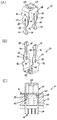
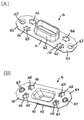
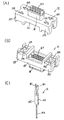
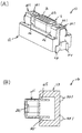
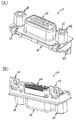
図に基づいて、本発明の固定具と電気コネクタの一実施例について説明する。図1(A)は本発明の電気コネクタを嵌合方向上方からみた斜視図であり、(B)は本発明の電気コネクタを接続部方向下側からみた斜視図である。図2(A)は固定具を嵌合方向上方からみた斜視図であり、(B)は固定具を接続部方向下側からみた斜視図であり、(C)は固定具部分で断面した部分的な横断面図である。図3(A)はシェルを嵌合方向上方からみた斜視図であり、(B)はシェルを接続部方向下側からみた斜視図である。図4(A)はハウジングを嵌合方向上方からみた斜視図であり、(B)はハウジングを接続部方向下側からみた斜視図であり、(C)はコンタクトの斜視図である。図5は図2とは別の固定具の斜視図である。図6は別の導通手段の説明図である。図7(A)は従来の電気コネクタを嵌合方向上方からみた斜視図であり、(B)は従来の電気コネクタを接続部方向下側からみた斜視図である。 One embodiment of the fixture and electrical connector of the present invention will be described with reference to the drawings. FIG. 1A is a perspective view of the electrical connector of the present invention as viewed from above in the fitting direction, and FIG. 1B is a perspective view of the electrical connector of the present invention as viewed from below in the connecting portion direction. 2A is a perspective view of the fixture viewed from the upper side in the fitting direction, FIG. 2B is a perspective view of the fixture viewed from the lower side in the connection portion direction, and FIG. FIG. 3A is a perspective view of the shell as seen from above in the fitting direction, and FIG. 3B is a perspective view of the shell as seen from below in the connecting portion direction. 4A is a perspective view of the housing as viewed from above in the fitting direction, FIG. 4B is a perspective view of the housing as viewed from below in the connecting portion direction, and FIG. 4C is a perspective view of the contact. FIG. 5 is a perspective view of a fixture different from that shown in FIG. FIG. 6 is an explanatory diagram of another conducting means. FIG. 7A is a perspective view of a conventional electrical connector as viewed from above in the fitting direction, and FIG. 7B is a perspective view of the conventional electrical connector as viewed from below in the connecting portion direction.
最初に、本発明のポイントである固定具20について説明する。前記固定具20は金属製であり、公知技術のプレス加工によって製作されている。前記固定具20の材質としては、バネ性や導電性や強度などが要求されるので、黄銅やベリリウム銅やリン青銅や鉄等を挙げることができる。本実施例における固定具20は、図2のように略U形状をしている。前記固定具20は、少なくとも、相手物との嵌合側に係合手段(雌ネジ部22)と基板側に基板への装着手段24と前記シェル16との導通手段と前記ハウジング12への固定手段を有している。
First, the
相手物との係合手段22としては、相手物との保持力やコネクタの小型化や操作性などを考慮して適宜選択(設計)される。前記係合手段22としては、ネジや引っ掛けなどを挙げることができる。本実施例では、嵌合側(U字形状の頂部)に雌ネジ部22を形成している。該雌ネジ部22は、プレス加工後に切削加工により後加工される。また、雄ネジを誘い易くするために、前記雌ネジ部22の外周には、誘い部32を設けることが望ましい。本実施例では前記誘い部32はテーパー形状にしているが、雄ネジを誘い易くできれば、如何なる形状でもよい。例えば、C面取りやR形状のようなものでもよい。
The engagement means 22 with the counterpart is appropriately selected (designed) in consideration of the holding force with the counterpart, the miniaturization and operability of the connector, and the like. Examples of the engaging
基板への装着手段24としては、実装強度や占有面積や高密度化などを考慮して適宜設計される。前記装着手段24としては、半田付けやプレスフィットなどを挙げることができる。本実施例ではディップタイプの半田付けにより基板に装着している。本実施例では、ディップタイプにしたが、表面実装(SMT)タイプ(図示せず)であってもよい。本実施例では、基板に仮止めし易いように、前記装着部24を二股形状にしている。つまり、幅方向の中央部分にスリット34を設け、脚部36部分に弾性を持たせている。
また、前記固定具20には、前記ハウジング12への固定手段として、図2のように幅方向両側に固定部分30が設けられている。本実施例では、固定手段として圧入代を設け、圧入によって、前記ハウジング12の装着孔124に圧入している。本実施例では圧入により固定したが、前記固定具20の保持力が満足できれば、如何なる方法であってもよい。例えば、溶着や引っ掛け等であってもよい。
The mounting means 24 on the substrate is appropriately designed in consideration of mounting strength, occupied area, high density, and the like. Examples of the mounting means 24 include soldering and press fitting. In this embodiment, it is mounted on the substrate by dip type soldering. In this embodiment, the dip type is used, but a surface mount (SMT) type (not shown) may be used. In this embodiment, the mounting
Further, the fixing
前記シェル16との導通手段としては、導通性や強度や加工性などを考慮して適宜設計される。前記導通手段としては、ボスや接触片や圧入方式(シェルに固定具を圧入)などを挙げることができる。本実施例では前記シェル16に係合片165を設け、かつ、前記固定具20に凸部28を設け、前記係合片片165と前記凸部28を接触させることにより導通を図っている。本実施例では、導通手段として、前記固定具20に凸部28を設け、前記シェル16に係合片165を設け、図2(C)のように前記凸部28と前記係合片165を接触させることで行っている。前記固定具20の凸部28の形状・大きさは、前記シェル16の係合片165と接触(導通)出来れば、如何なるものであってもよいが、導通性や加工性や組立性等を考慮して適宜設計する。本実施例では、導通手段として、凸部28と係合片165との関係にしたが、前記固定具20側に接触片を設け、前記シェル16に前記接触片と接触できるボスや実施例同様の係合片165を設け、互いに接触できるようにしてもよい(図示せず)。
また、前記固定具20には、前記ハウジング12へ圧入する際の深さを位置決め及び前記シェル16との固定のための突出片26が設けられている。前記突出片26が前記シェル16の上面に接触まで圧入することで深さ方向の位置決め及び前記シェル16を固定することができる。さらに、前記突出片26としては、位置決め及び固定とは別に前記シェル16と接触させることで前記シェル16との導通手段としても用いることが可能である。前記突出片26の形状・大きさは、このような役割や加工性や導通性や前記シェル16との保持力等を考慮して適宜設計する。本実施例では、0.3〜1.0mm突出させている。
The conduction means with the
Further, the
次に、シェル16について説明する。該シェル16は金属製であり、公知技術のプレス加工によって製作されている。前記シェル16の材質としては、バネ性や導電性などが要求されるので、黄銅やベリリウム銅やリン青銅や鉄等を挙げることができる。本実施例におけるシェル16は、図3のように略T字形状をしている。前記シェル16は、少なくとも、本体161とフランジ163と前記ハウジング12の嵌合部18を覆う嵌合口162とを有している。
Next, the
前記シェル16の嵌合口162は、前記本体161から突出するように設けられ、前記ハウジング12の嵌合部18の形状に沿うように形成されている。つまり、嵌合口162は前記ハウジング12の嵌合部18をEMI対策のために覆っている。前記嵌合口162の形状・大きさは加工性や強度や前記ハウジング12の嵌合部18の形状や相手物(コネクタ)の嵌合性などを考慮して適宜設計する。
The
前記本体161のピッチ長手方向両側には、フランジ163が設けられており、前記フランジ163には前記固定具20と係合する係止孔166が設けられている。また、前記シェル16には前記固定具20との導通手段である略L字形状に折曲げられた係合片165が前記係止孔166に突出するように設けられている。前記係合片165が前記固定具20の凸部28と接触することで、前記固定具20と前記シェル16との導通を図っている。前記係止孔166と前記係合片165は、前記固定具20の形状及び凸部28に対応するように、各フランジ163に各2個計4個設けられている。
また、前記フランジ163には、パネルに取り付けるための孔167が設けられている。前記孔167とパネル(図示せず)にネジを挿入し、前記コネクタ10をパネルに取り付けている。
The
次に、コンタクト14について説明する。コンタクト14は金属製であり、公知技術のプレス加工によって製作されている。前記コンタクト14の材質としては、バネ性や導電性などが要求されるので、黄銅やベリリウム銅やリン青銅等を挙げることができる。本実施例におけるコンタクト14は、図4(C)のように板状をしている。前記コンタクト14は、少なくとも、一方の自由端側に相手物と接触する接触部141と他方の自由端側に基板に接続する接続部143と前記接触部141と前記接続部143との間に前記ハウジング12へ固定するための固定部142とを有している。
Next, the
前記接触部141は相手物と接触する部分であって、相手物と接触できれば良く、相手物の沿うような形状で、接続安定性や接触圧などを考慮して適宜設計している。本実施例ではチューニングフォークにしているが、相手物と接触できればどのような構造(タイプ)であってもよい。
前記接続部143は基板に実装する部分であって、基板の占有面積や基板の実装密度や接続強度などを考慮して適宜設計している。本実施例では基板の実装密度を考慮して表面実装(SMT)タイプにしている。
The
The
前記固定部142は前記ハウジング12に固定する部分であって、前記ハウジング12に固定できれば良く、保持力やコネクタの小型化や加工性などを考慮して適宜設計する。本実施例では圧入によって固定しているが、インサート成型や絶縁物同士の挟み込みや引っ掛け(ランス)であってもよい。
The fixing
最後に、ハウジング12について説明する。このハウジング12は電気絶縁性のプラスチックであり、公知技術の射出成形によって製作され、この材質としては寸法安定性や加工性やコスト等を考慮して適宜選択するが、一般的にはポリブチレンテレフタレート(PBT)やポリアミド(66PA、46PA、PA9T)や液晶ポリマー(LCP)やポリカーボネート(PC)やポニフェニレンサルファイド(PPS)やこれらの合成材料を挙げることができる。前記ハウジング12は、図4(A)及び(B)のように、逆T字形状をしている。前記ハウジング12は、主に、嵌合部18と本体部121とフランジ部122を有している。前記嵌合部18は本体部121から相手物との嵌合方向へ突出しており、前記フランジ部122は前記本体部121のピッチ長手方向両側に設けられている。
Finally, the
前記ハウジング12には、所要数のコンタクト14が装着される挿入孔123が設けられており、圧入や引っ掛け(ランス)や溶着等によって固定されている。前記挿入孔123は前記コンタクト14が挿入できればよく、保持力や強度や加工性等を考慮して適宜設計する。前記挿入孔123は前記嵌合部18と前記本体部121に連設するように設けられている。前記嵌合部18側の挿入孔123は相手物が入り易く、かつ、相手物をガイドできるように設けられており、前記本体部121側の挿入孔123は前記コンタクト14を固定できるように設けられている。
The
両方の前記フランジ部122には、前記固定具20を固定(保持)するための装着孔124が設けられている。前記装着孔124は、前記固定具20の形状及び前記シェル16の係合片165に対応するように、各フランジ部122に各2個計4個設けられている。本実施例では、前記装着孔124は略T字形状をしている。前記装着孔124の形状・大きさは、前記固定具20が固定でき、前記シェル16の係合片165が変位できれば、如何なるものであってもよいが、前記固定具20の形状や前記シェル16の係合片165の変位量や前記固定具20と前記シェル16との導通性や前記ハウジング12の加工性等を考慮して適宜設計する。
Both
図5及び図6に基づいて、別の実施形態について説明する。ここでは、上記実施例と相違する部分についてのみ説明する。図5のように、別の固定具201は、略筐体状をしており、上述した固定具20と同様に、少なくとも、相手物との嵌合側に係合手段(雌ネジ部221)と基板側に基板への装着手段241と前記シェル16との導通手段と前記ハウジング12への固定手段を有している。相手物との係合手段としては、相手物との保持力やコネクタの小型化や操作性などを考慮して適宜選択(設計)される。前記係合手段としては、ネジや引っ掛けなどを挙げることができる。本実施例では、嵌合側(U字形状の頂部)に雌ネジ部221を形成している。該雌ネジ部221は、プレス加工後に切削加工により後加工される。また、雄ネジを誘い易くするために、前記雌ネジ部221の外周には、誘い部321を設けることが望ましい。本実施例では前記誘い部321はテーパー形状にしているが、雄ネジを誘い易くできれば、如何なる形状でもよい。例えば、C面取りやR形状のようなものでもよい。
基板への装着手段としては、実装強度や占有面積や高密度化などを考慮して適宜設計される。前記装着手段としては、半田付けやプレスフィットなどを挙げることができる。本実施例ではディップタイプの半田付けにより基板に装着している。本実施例では、ディップタイプにしたが、表面実装(SMT)タイプ(図示せず)であってもよい。本実施例では、基板に仮止めし易いように、前記装着部241を二股形状にしている。
また、前記固定具20には、前記ハウジング12への固定手段として、図5のように前記装着部241付近に固定部分301が設けられている。本実施例では、固定手段として圧入代を設け、圧入によって、前記ハウジング12の装着溝に圧入している。本実施例では圧入により固定したが、前記固定具201の保持力が満足できれば、如何なる方法であってもよい。例えば、溶着や引っ掛け等であってもよい。
前記シェル16との導通手段としては、導通性や強度や加工性などを考慮して適宜設計される。前記導通手段としては、ボスや接触片や圧入方式(シェルに固定具を圧入)などを挙げることができる。本実施例では前記シェル16に係合片165を設け、該係合片片を前記固定具201に接触させることにより導通を図っている。本実施例では、導通手段として、前記シェル16に係合片165を設け、図6(B)のように前記係合片165を前記固定具201に接触させることで行っている。本実施例では、導通手段として、前記係合片165を前記固定具201に接触させる関係にしたが、前記固定具201側に接触片を設け、前記シェル16に前記接触片と接触できるボスや実施例同様の係合片165を設け、互いに接触できるようにしてもよい(図示せず)。
また、前記固定具201には、前記ハウジング12へ圧入する際の深さを位置決めするための突出片26が設けられている。前記突出片26が前記シェル16の上面に接触まで圧入することで深さ方向の位置決めをすることができる。さらに、前記突出片26としては、位置決め及び固定とは別に前記シェル16と接触させることで前記シェル16との導通手段としても用いることが可能である。前記突出片26の形状・大きさは、このような役割や加工性や導通性や前記シェル16との保持力等を考慮して適宜設計する。本実施例では、0.3〜1.0mm突出させている。
前記ハウジング12及び前記シェル16は、前記固定具201に沿うように適宜設計する。前記固定具201を用いる前記シェル16はパネルに取り付けるタイプではないため、図3のような孔167は設ける必要はない。
Another embodiment will be described based on FIGS. 5 and 6. Here, only the parts different from the above embodiment will be described. As shown in FIG. 5, another fixing
The mounting means on the substrate is appropriately designed in consideration of mounting strength, occupied area, high density, and the like. Examples of the mounting means include soldering and press fitting. In this embodiment, it is mounted on the substrate by dip type soldering. In this embodiment, the dip type is used, but a surface mount (SMT) type (not shown) may be used. In this embodiment, the mounting
Further, the fixing
The conduction means with the
The
The
本発明の活用例としては、FA機器やOA機器やテレビやパーソナルコンピュータ等の電気機器や電子機器の基板に実装される電気コネクタに活用され、特に、相手物との係合手段と基板への装着手段を一体構造にするとともにシェルとの導通手段を備えた構造に関するものである。 As an application example of the present invention, it is used for an electrical connector mounted on a board of an electric device or an electronic device such as an FA device, an OA device, a television or a personal computer, and in particular, an engagement means with a counterpart and the substrate. The present invention relates to a structure in which the mounting means is integrated and provided with means for conducting with the shell.
10 電気コネクタ
12 ハウジング
121 本体部
122 フランジ部
123 挿入孔
124 装着孔
14 コンタクト
141 接触部
142 固定部
143 接続部
16 シェル
161 本体
162 嵌合口
163 フランジ
165 係合片
166 係止孔
167 孔
18 嵌合部
20、201 固定具
22、221 雌ネジ部(係合手段)
24、241 装着部(装着手段)
26 突出片
28 凸部
30、301 固定部分
32、321 誘い部
34 スリット
36 脚部
60 電気コネクタ
62 ハウジング
64 コンタクト
66 シェル
68 ジャックソケット
70 固定具
DESCRIPTION OF
24, 241 mounting portion (mounting means)
26
Claims (6)
該固定具は、相手物との係合手段と前記装着手段とを、導電材料をプレス加工により一体構造に成型し、
さらに、シェルとの導通手段を有し、
係合手段として、相手物との嵌合方向に雌ネジ部を形成し、
前記シェルと前記固定具の導通手段とを接触・導通させることを特徴とする固定具。 In a fixture having means for mounting on a substrate,
The fixing tool is formed by molding a conductive material into a unitary structure by pressing the engaging means with the counterpart and the mounting means.
Furthermore, it has a means for conduction with the shell,
As an engaging means, a female screw part is formed in the fitting direction with the counterpart,
A fixture characterized in that the shell and the conduction means of the fixture are brought into contact with each other.
複数のコンタクトと、該コンタクトが保持・配列されるとともに相手物との嵌合部を含むハウジングと、該ハウジングの嵌合部を覆うシェルと、相手物との係合手段と、基板への装着手段とを備える電気コネクタにおいて、
導電材料をプレス加工により前記係合手段と前記装着手段とを一体構造に成型するとともに前記シェルとの導通手段を有する固定具を配置し、
前記固定具の係合手段として、相手物との嵌合方向に雌ネジ部を形成し、
前記シェルと前記固定具の導通手段とを接触・導通させることを特徴とする電気コネクタ。 An electrical connector mounted on a board,
A plurality of contacts, a housing in which the contacts are held and arranged and including a fitting portion with a counterpart, a shell covering the fitting portion of the housing, an engagement means with the counterpart, and mounting on the substrate An electrical connector comprising means,
The engaging means and the mounting means are molded into an integral structure by pressing a conductive material, and a fixture having a conduction means with the shell is disposed.
As an engaging means of the fixing tool, a female screw part is formed in a fitting direction with a counterpart,
An electrical connector characterized in that the shell and a conduction means of the fixture are brought into contact with each other.
Priority Applications (3)
| Application Number | Priority Date | Filing Date | Title |
|---|---|---|---|
| JP2008197650A JP4916031B2 (en) | 2008-07-31 | 2008-07-31 | Fixing tool and electrical connector using the fixing tool |
| CN2009101590202A CN101640351B (en) | 2008-07-31 | 2009-07-29 | Fixing member and electric connector using the same |
| KR1020090069906A KR101121696B1 (en) | 2008-07-31 | 2009-07-30 | Fixture and electrical connector using the fixture |
Applications Claiming Priority (1)
| Application Number | Priority Date | Filing Date | Title |
|---|---|---|---|
| JP2008197650A JP4916031B2 (en) | 2008-07-31 | 2008-07-31 | Fixing tool and electrical connector using the fixing tool |
Related Child Applications (1)
| Application Number | Title | Priority Date | Filing Date |
|---|---|---|---|
| JP2011282720A Division JP5078187B2 (en) | 2011-12-26 | 2011-12-26 | Fixing tool and electrical connector using the fixing tool |
Publications (2)
| Publication Number | Publication Date |
|---|---|
| JP2010034003A true JP2010034003A (en) | 2010-02-12 |
| JP4916031B2 JP4916031B2 (en) | 2012-04-11 |
Family
ID=41615216
Family Applications (1)
| Application Number | Title | Priority Date | Filing Date |
|---|---|---|---|
| JP2008197650A Active JP4916031B2 (en) | 2008-07-31 | 2008-07-31 | Fixing tool and electrical connector using the fixing tool |
Country Status (3)
| Country | Link |
|---|---|
| JP (1) | JP4916031B2 (en) |
| KR (1) | KR101121696B1 (en) |
| CN (1) | CN101640351B (en) |
Cited By (1)
| Publication number | Priority date | Publication date | Assignee | Title |
|---|---|---|---|---|
| LU502822B1 (en) * | 2022-09-22 | 2024-03-22 | Phoenix Contact Gmbh & Co | Electrical connector |
Families Citing this family (4)
| Publication number | Priority date | Publication date | Assignee | Title |
|---|---|---|---|---|
| CN101820124A (en) * | 2010-05-07 | 2010-09-01 | 福建捷联电子有限公司 | Steel casing over board foot additional fixing structure |
| DE102012101813B3 (en) * | 2012-03-05 | 2013-06-13 | Phoenix Contact Gmbh & Co. Kg | Connectors |
| CN108616007A (en) * | 2018-06-04 | 2018-10-02 | 安徽艾伊德动力科技有限公司 | A kind of protection against rodents type high-tension connector for electric vehicle |
| CN109140326B (en) * | 2018-10-11 | 2024-04-02 | 中山市鼎亮照明电器有限公司 | Lamp arm mounting structure and ceiling lamp |
Citations (2)
| Publication number | Priority date | Publication date | Assignee | Title |
|---|---|---|---|---|
| JP2000133345A (en) * | 1998-10-28 | 2000-05-12 | D D K Ltd | Mounting part of electric connector |
| JP2004227880A (en) * | 2003-01-22 | 2004-08-12 | D D K Ltd | Connector |
Family Cites Families (6)
| Publication number | Priority date | Publication date | Assignee | Title |
|---|---|---|---|---|
| JP3329102B2 (en) * | 1994-11-10 | 2002-09-30 | オムロン株式会社 | Electrical connector |
| JP3168317B2 (en) * | 1996-02-19 | 2001-05-21 | 登騏企業股▲分▼有限公司 | Telephone socket with metal case and method of manufacturing the same |
| DE19607548C2 (en) * | 1996-02-28 | 1998-02-26 | Siemens Ag | Angled press-in connector for pressing into holes in a printed circuit board |
| US6033250A (en) * | 1997-03-31 | 2000-03-07 | The Whitaker Corporation | Latching connector |
| JP2007299687A (en) * | 2006-05-02 | 2007-11-15 | Yazaki Corp | Connector structure |
| CN201041894Y (en) * | 2007-02-09 | 2008-03-26 | 富士康(昆山)电脑接插件有限公司 | Electric connector |
-
2008
- 2008-07-31 JP JP2008197650A patent/JP4916031B2/en active Active
-
2009
- 2009-07-29 CN CN2009101590202A patent/CN101640351B/en active Active
- 2009-07-30 KR KR1020090069906A patent/KR101121696B1/en active IP Right Grant
Patent Citations (2)
| Publication number | Priority date | Publication date | Assignee | Title |
|---|---|---|---|---|
| JP2000133345A (en) * | 1998-10-28 | 2000-05-12 | D D K Ltd | Mounting part of electric connector |
| JP2004227880A (en) * | 2003-01-22 | 2004-08-12 | D D K Ltd | Connector |
Cited By (2)
| Publication number | Priority date | Publication date | Assignee | Title |
|---|---|---|---|---|
| LU502822B1 (en) * | 2022-09-22 | 2024-03-22 | Phoenix Contact Gmbh & Co | Electrical connector |
| WO2024061738A1 (en) * | 2022-09-22 | 2024-03-28 | Phoenix Contact Gmbh & Co. Kg | Electrical plug-in connection |
Also Published As
| Publication number | Publication date |
|---|---|
| KR101121696B1 (en) | 2012-02-28 |
| CN101640351B (en) | 2012-09-26 |
| JP4916031B2 (en) | 2012-04-11 |
| KR20100014155A (en) | 2010-02-10 |
| CN101640351A (en) | 2010-02-03 |
Similar Documents
| Publication | Publication Date | Title |
|---|---|---|
| JP5250450B2 (en) | Electrical connector | |
| US7458822B2 (en) | Electrical connector and combination connector having the same | |
| KR102111728B1 (en) | Electric connector | |
| JP2007018785A (en) | Connector | |
| JP6006356B2 (en) | Contact and connector using the contact | |
| JP6462634B2 (en) | connector | |
| US20070155227A1 (en) | Electrical connector | |
| JPWO2019077840A1 (en) | Electrical connector | |
| JP4916031B2 (en) | Fixing tool and electrical connector using the fixing tool | |
| JP5665585B2 (en) | Electrical connector | |
| JP5134943B2 (en) | connector | |
| JP2006019039A (en) | Electric connector | |
| JP6239582B2 (en) | Electrical connector | |
| JP2012256609A (en) | Fastener and electric connector using the same | |
| JP5078187B2 (en) | Fixing tool and electrical connector using the fixing tool | |
| US20090298345A1 (en) | Connector | |
| JP2008171627A (en) | Female terminal fitting | |
| JP4044646B2 (en) | Electrical connector | |
| JPH09283223A (en) | Electric connector | |
| JP5567868B2 (en) | Receptacle coaxial connector | |
| JP2008251511A (en) | Electrical connector | |
| TW201023438A (en) | Electrical connector | |
| US9941649B2 (en) | Interboard connection connector with battery connector | |
| CN105048225A (en) | Coaxial connector | |
| JPH1126105A (en) | Electric connector |
Legal Events
| Date | Code | Title | Description |
|---|---|---|---|
| A621 | Written request for application examination |
Free format text: JAPANESE INTERMEDIATE CODE: A621 Effective date: 20110713 |
|
| A871 | Explanation of circumstances concerning accelerated examination |
Free format text: JAPANESE INTERMEDIATE CODE: A871 Effective date: 20110802 |
|
| A975 | Report on accelerated examination |
Free format text: JAPANESE INTERMEDIATE CODE: A971005 Effective date: 20110817 |
|
| A977 | Report on retrieval |
Free format text: JAPANESE INTERMEDIATE CODE: A971007 Effective date: 20111117 |
|
| A131 | Notification of reasons for refusal |
Free format text: JAPANESE INTERMEDIATE CODE: A131 Effective date: 20111122 |
|
| RD03 | Notification of appointment of power of attorney |
Free format text: JAPANESE INTERMEDIATE CODE: A7423 Effective date: 20111201 |
|
| RD13 | Notification of appointment of power of sub attorney |
Free format text: JAPANESE INTERMEDIATE CODE: A7433 Effective date: 20111208 |
|
| A521 | Request for written amendment filed |
Free format text: JAPANESE INTERMEDIATE CODE: A523 Effective date: 20111216 |
|
| A521 | Request for written amendment filed |
Free format text: JAPANESE INTERMEDIATE CODE: A821 Effective date: 20111209 |
|
| TRDD | Decision of grant or rejection written | ||
| A01 | Written decision to grant a patent or to grant a registration (utility model) |
Free format text: JAPANESE INTERMEDIATE CODE: A01 Effective date: 20120123 |
|
| A01 | Written decision to grant a patent or to grant a registration (utility model) |
Free format text: JAPANESE INTERMEDIATE CODE: A01 |
|
| A61 | First payment of annual fees (during grant procedure) |
Free format text: JAPANESE INTERMEDIATE CODE: A61 Effective date: 20120123 |
|
| FPAY | Renewal fee payment (event date is renewal date of database) |
Free format text: PAYMENT UNTIL: 20150203 Year of fee payment: 3 |
|
| R150 | Certificate of patent or registration of utility model |
Ref document number: 4916031 Country of ref document: JP Free format text: JAPANESE INTERMEDIATE CODE: R150 Free format text: JAPANESE INTERMEDIATE CODE: R150 |
|
| R250 | Receipt of annual fees |
Free format text: JAPANESE INTERMEDIATE CODE: R250 |
|
| R250 | Receipt of annual fees |
Free format text: JAPANESE INTERMEDIATE CODE: R250 |
|
| R250 | Receipt of annual fees |
Free format text: JAPANESE INTERMEDIATE CODE: R250 |
|
| R250 | Receipt of annual fees |
Free format text: JAPANESE INTERMEDIATE CODE: R250 |
|
| R250 | Receipt of annual fees |
Free format text: JAPANESE INTERMEDIATE CODE: R250 |
|
| R250 | Receipt of annual fees |
Free format text: JAPANESE INTERMEDIATE CODE: R250 |
|
| R250 | Receipt of annual fees |
Free format text: JAPANESE INTERMEDIATE CODE: R250 |
|
| R250 | Receipt of annual fees |
Free format text: JAPANESE INTERMEDIATE CODE: R250 |
|
| R250 | Receipt of annual fees |
Free format text: JAPANESE INTERMEDIATE CODE: R250 |
|
| R250 | Receipt of annual fees |
Free format text: JAPANESE INTERMEDIATE CODE: R250 |