US6033250A - Latching connector - Google Patents
Latching connector Download PDFInfo
- Publication number
- US6033250A US6033250A US09/008,638 US863898A US6033250A US 6033250 A US6033250 A US 6033250A US 863898 A US863898 A US 863898A US 6033250 A US6033250 A US 6033250A
- Authority
- US
- United States
- Prior art keywords
- latch
- main body
- housing
- spring
- latching
- Prior art date
- Legal status (The legal status is an assumption and is not a legal conclusion. Google has not performed a legal analysis and makes no representation as to the accuracy of the status listed.)
- Expired - Lifetime
Links
Images
Classifications
-
- H—ELECTRICITY
- H01—ELECTRIC ELEMENTS
- H01R—ELECTRICALLY-CONDUCTIVE CONNECTIONS; STRUCTURAL ASSOCIATIONS OF A PLURALITY OF MUTUALLY-INSULATED ELECTRICAL CONNECTING ELEMENTS; COUPLING DEVICES; CURRENT COLLECTORS
- H01R13/00—Details of coupling devices of the kinds covered by groups H01R12/70 or H01R24/00 - H01R33/00
- H01R13/62—Means for facilitating engagement or disengagement of coupling parts or for holding them in engagement
- H01R13/627—Snap or like fastening
- H01R13/6275—Latching arms not integral with the housing
-
- Y—GENERAL TAGGING OF NEW TECHNOLOGICAL DEVELOPMENTS; GENERAL TAGGING OF CROSS-SECTIONAL TECHNOLOGIES SPANNING OVER SEVERAL SECTIONS OF THE IPC; TECHNICAL SUBJECTS COVERED BY FORMER USPC CROSS-REFERENCE ART COLLECTIONS [XRACs] AND DIGESTS
- Y10—TECHNICAL SUBJECTS COVERED BY FORMER USPC
- Y10S—TECHNICAL SUBJECTS COVERED BY FORMER USPC CROSS-REFERENCE ART COLLECTIONS [XRACs] AND DIGESTS
- Y10S439/00—Electrical connectors
- Y10S439/953—Electrical connectors with latch rod to be retainingly received by opening of mating connector
Definitions
- This invention is related to electrical connectors and more particularly a latching mechanism for such connectors.
- Electrical connections to printed circuit boards are accomplished in several ways. Connections are made through soldering components directly to pads or traces on the printed circuit board, through card edge connections to an electrical connector which is integral to another device or circuit board, and also between a header mounted on the printed circuit board and an electrical connector such as a plug at the end of a wire harness.
- this problem is addressed by mechanically securing the harness plug connector directly to the printed circuit board through fasteners such as bolts or screws.
- This type of arrangement is not easily disconnectable and also requires additional board real estate for the fasteners. It is therefore desirable to secure the header connector to the printed circuit board and establish electrical connection to the harness plug connector with sufficient mechanical retention to prevent separation or breaking of either the header connector or the harness plug connector.
- a latch is disposed along an edge of the plug and has a main body from which a latch arm is bent at a right angle and extends along a central axis from the body to a free end.
- the free end is defined by a securing portion being slightly larger than the remainder of the latch arm.
- the securing portion has a locking projection extending therefrom at the free end.
- a spring arm also extends at an acute angle from the body angle and towards the latch arm. The free end of the spring arm is profiled to engage an outer surface of the plug housing so that when a force is applied to the body it will cause deflection of the spring arm to effect a motion of the latch arm along the central axis.
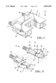
- FIG. 1 shows a three-dimensional view of the electrical connector according to the present invention.
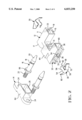
- FIG. 2 shows an exploded three-dimensional view of the electrical connector of FIG. 1.
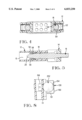
- FIG. 3 shows a three-dimensional view of the electrical connector of FIG. 1 wherein the housings are displayed in phantom.
- FIG. 4 shows a cross-sectional view of the connector of FIG. 1 having the latches depressed in a release position.
- FIG. 5 shows a cross-sectional view of the connector of FIG. 1 having the latch in a prelatch position.
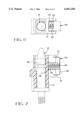
- FIG. 6 shows a partial end view of an alternate embodiment having a coil spring in place of the spring arms.
- FIG. 7 shows a cross sectional view similar to that of FIG. 5 for the alternate embodiment of FIG. 6.
- FIG. 8 shows a partial cross sectional view similar to that of FIG. 7 for a second alternate embodiment wherein the coil spring is replaced by a pliable ball.
- This electrical connector 10 consists two mating halves 12,14.
- the plug 12 features a plurality of contact-receiving openings 13 and a pair of post-receiving openings 15 which extend from the mating end 17 to the cable end 19. Latches 30 are disposed along the sides of the plug 12.
- the header 14 has a pair of post-receiving openings 24 (FIG. 2) disposed on opposite ends and a plug-receiving area 26 between the two post-receiving openings 24.
- a pair of posts 16 are disposed inside each post-receiving opening 24.
- the plug 12 consists a housing 11 having a plurality of contact-receiving openings 13 extending from the mating end 17 toward the cable end 19.
- a pair of post-receiving openings 15 also extend from the mating end 17 to the cable end 19.
- These post-receiving openings 15 are defined by a pair of sidewalls 38,40.
- a plug section 44 is disposed around the plurality of contact-receiving openings 13.
- a pair of latch-receiving sections 32 are disposed along sides of the housing 11 and consists of a spring channel 33 and a latch opening 34 which extends from the spring channel 33 to the side wall 40.
- the latch opening 34 is profiled to have a shoulder 42 extending from the spring channel 33 partially into the latch opening 34. Stop surface 36 is defined by the end of the shoulder 42 which is inside the latch-receiving opening 34.
- a pair of latches 30 are provided along the sides of the housing 11 and are received into the latch-receiving sections 32.
- Each latch 30 consists of a main body 50 from which a pair of spring arms 52 and a pair of latch arms 54 extend.
- the latch arms 54 extend at substantially a right angle from the main body 50.
- a securing tab 56 is provided near each of the free ends 62 of the latch arms 54.
- Locking projections 58 extend from the securing tabs 56 towards each other.
- a pair of spring arms 52 extend from the main body 50 at an acute angle toward the latch arms 54. Free ends 60 of the spring arms 52 are flared and profiled to slidingly engage the spring channels 33.
- the header 14 is shown consisting of a housing 64 having a pair of post-receiving openings 24 and a plug-receiving opening 26 disposed between the post-receiving openings 24.
- a pair of posts 16 are generally cylindrical and profiled to have a threaded section 22, an annular flange 66, an annular groove 18, and a tapered section 20. The threaded sections 22 are received in the post-receiving openings 24.
- the latches 30 are first assembled into the housing 11 by urging the spring arms 54 toward each other such that they clear the shoulders 42.
- the latch is then urged into the latch-receiving opening 34 until the tab 56 passes and engages the stop surface 36 causing the latch arms 54 to return to their relaxed position and lock behind the shoulder 42. It should be understood that when in the locked position, the free ends 60 of the spring arms 52 will be in engagement with the spring channel 33 in order to urge the tab 56 toward the stop surface 36.
- Posts 16 are assembled to the header 14 through post-receiving openings 24.
- the threaded sections 22 pass through the openings 24 and are secured to a printed circuit board using nuts (not shown). This provides mechanical connection to the printed circuit board.
- FIGS. 3-5 A mating cycle will now be described with reference to FIGS. 3-5.
- the connector 10 is shown in the mated condition with the connector housings 11,14 shown in phantom.
- contacts have been removed in order to more clearly show the latching mechanism.
- the latches 30 are disposed such that the tabs 56 are in engagement with the stop surfaces 36.
- the free ends 60 are in engagement with the spring channel 33.
- Locking projections 58 are positioned inside annular grooves 18 of the posts 16. When the posts 16 are secured to a printed circuit board, the plug 12 will be prevented from separation due to the engagement of the locking projections 58 with the annular grooves 18.
- the latches 30 may be depressed in the area of the main body 50 toward each other.
- FIG. 5 shows a cross sectional view of the plug 12 and header 14 taken along one side.
- the plug 12 and header 14 are mated by simply inserting the posts 16 into the post-receiving openings 15 of the plug 12.
- the tabs 56 and locking projections 58 ride up the tapered surface 20 of the post 16 as the plug 12 is mated to the header 14.
- the plug 12 is further urged towards the header 14 until the locking projections 58 are aligned with and snapped into the annular groove 18 as shown in FIG. 3.
- FIGS. 6 and 7 show a first alternate embodiment of the present invention.
- FIG. 6 represents a partial sectional view similar to that of FIG. 4 in which the spring arms 52 of the previous embodiment are replaced with a coil spring 152.
- the coil spring 152 is disposed between the main body 150 and the spring channel 133.
- the main body 150 has two overstress extensions 151 (FIG. 7) extending therefrom to prevent the latch 130 from traveling beyond the release position as shown for example in FIG. 4.
- the spring channel 133 is profiled to have a spring receiving area 135 in the vicinity of the latch opening 34.
- the coil spring 152 serves to urge the latch 130 outward such that the tab 156 is biased against the stop surface 136 of the housing 111.
- the latch arms 54 are structurally the same as those of the previous embodiment.
- FIG. 8 shows yet another embodiment of the present invention in which the coil spring 152 of FIG. 7 is replaced by a pliable ball 252.
- the latch 150 is structurally the same as the latch 150 of the previous embodiment.
- the pliable ball 252 may be formed of a rubber of other suitable pliable material which has the ability to exert a sufficient force on the main body 150 to bias the tab 156 against the stop surface 136.
- the pliable ball must be appropriately sized to allow sufficient travel of the latch arms 154 between the latching position (FIG. 3) and the release position (FIG. 4.).
- An advantage of this invention is that it provides a reliable mechanical and electrical connection between a plug 12 and a header 14 mounted to a printed circuit board.
- the latch 30 is housed almost completely inside the plug in order to minimize the board real estate necessary for mechanical connection.
Abstract
Description
Claims (9)
Priority Applications (1)
Application Number | Priority Date | Filing Date | Title |
---|---|---|---|
US09/008,638 US6033250A (en) | 1997-03-31 | 1998-01-16 | Latching connector |
Applications Claiming Priority (2)
Application Number | Priority Date | Filing Date | Title |
---|---|---|---|
US4215697P | 1997-03-31 | 1997-03-31 | |
US09/008,638 US6033250A (en) | 1997-03-31 | 1998-01-16 | Latching connector |
Publications (1)
Publication Number | Publication Date |
---|---|
US6033250A true US6033250A (en) | 2000-03-07 |
Family
ID=21920329
Family Applications (1)
Application Number | Title | Priority Date | Filing Date |
---|---|---|---|
US09/008,638 Expired - Lifetime US6033250A (en) | 1997-03-31 | 1998-01-16 | Latching connector |
Country Status (3)
Country | Link |
---|---|
US (1) | US6033250A (en) |
JP (1) | JPH10284174A (en) |
GB (1) | GB2325575A (en) |
Cited By (14)
Publication number | Priority date | Publication date | Assignee | Title |
---|---|---|---|---|
US6304456B1 (en) * | 1999-07-22 | 2001-10-16 | Hewlett-Packard Company | Housing assembly having simplified circuit board assembly, retention, and electrical connection features |
US20040023526A1 (en) * | 2002-08-02 | 2004-02-05 | Enplas Corporation | Socket for electrical parts |
US20040087202A1 (en) * | 2002-11-04 | 2004-05-06 | Litton Systems, Inc. | Slotted guide pin and latch assembly |
US20080108244A1 (en) * | 2006-11-03 | 2008-05-08 | Cadwell Laboratories, Inc. | Electrical connector locking system |
US7387525B1 (en) * | 2007-10-12 | 2008-06-17 | Cheng Uei Precision Industry Co., Ltd. | Plug connector |
US20110136370A1 (en) * | 2008-09-02 | 2011-06-09 | Zhou nan-qing | Connecting structure of a lamp head base and a lamp tube base |
US20110189880A1 (en) * | 2010-02-01 | 2011-08-04 | Sonion A/S | assembly comprising a male and a female plug member, a male plug member and a female plug member |
US7997921B1 (en) * | 2010-10-15 | 2011-08-16 | Lockheed Martin Corporation | Connecting elements having a stub surrounded by a hollow stalk with a flange |
US20120052710A1 (en) * | 2010-08-25 | 2012-03-01 | Deehr Mark G | Apparatus and method for attaching a header to a housing of an implantable device |
US8152549B1 (en) | 2010-11-01 | 2012-04-10 | Lockheed Martin Corporation | Multiple stem design for high density interconnects |
US20120088387A1 (en) * | 2010-10-11 | 2012-04-12 | Walker Kevin E | Positive safety latch |
US20130130531A1 (en) * | 2011-11-22 | 2013-05-23 | Hon Hai Precision Industry Co., Ltd. | Locking mechanism and plug device using the same |
US20170117677A1 (en) * | 2015-10-27 | 2017-04-27 | Extensive Energy Technologies Partnership | Latching rotary connector system |
CN112290302A (en) * | 2020-09-28 | 2021-01-29 | 上海航天科工电器研究院有限公司 | Quick locking structure connector |
Families Citing this family (2)
Publication number | Priority date | Publication date | Assignee | Title |
---|---|---|---|---|
JP4916031B2 (en) * | 2008-07-31 | 2012-04-11 | 第一電子工業株式会社 | Fixing tool and electrical connector using the fixing tool |
JP6229841B2 (en) * | 2014-02-07 | 2017-11-15 | 第一精工株式会社 | Interengagement connector device |
Citations (12)
Publication number | Priority date | Publication date | Assignee | Title |
---|---|---|---|---|
US4880393A (en) * | 1988-08-05 | 1989-11-14 | Moji & Co., Ltd. | Connector with locking mechanism |
US4915650A (en) * | 1988-05-13 | 1990-04-10 | Amp Incorporated | Electrical terminals and method for terminating flat power cable |
US4993967A (en) * | 1989-07-03 | 1991-02-19 | Yazaki Corporation | Electric connector with a double locking mechanism |
US5041017A (en) * | 1989-08-09 | 1991-08-20 | Yazaki Corporation | Perfect coupling confirming mechanism for an electric connector |
US5183430A (en) * | 1986-04-28 | 1993-02-02 | James Swann | Geometric toy construction system |
US5254013A (en) * | 1990-04-25 | 1993-10-19 | Hirose Electric Co., Ltd. | Push-pull lock connector |
US5580268A (en) * | 1995-03-31 | 1996-12-03 | Molex Incorporated | Lockable electrical connector |
US5702266A (en) * | 1996-05-03 | 1997-12-30 | Molex Incorporated | Electrical connector latching system |
US5749745A (en) * | 1994-11-09 | 1998-05-12 | Carl-Zeiss-Stiftung | Adapter connector and camera assembly equipped with said adapter connector |
US5839968A (en) * | 1996-01-16 | 1998-11-24 | Theragolf, Ltd. | Club swing training method and apparatus therefor |
US5876230A (en) * | 1996-02-09 | 1999-03-02 | Sumitomo Wiring Systems, Ltd. | Connector |
US5971790A (en) * | 1997-10-31 | 1999-10-26 | The Whitaker Corporation | Unitary spring latch for an electrical connector assembly |
Family Cites Families (2)
Publication number | Priority date | Publication date | Assignee | Title |
---|---|---|---|---|
US4610564A (en) * | 1984-10-03 | 1986-09-09 | Compagnie Deutsch | Device for guiding and locking the coupling of a connector |
US5775931A (en) * | 1996-05-03 | 1998-07-07 | Molex Incorporated | Electrical connector latching system |
-
1998
- 1998-01-16 US US09/008,638 patent/US6033250A/en not_active Expired - Lifetime
- 1998-03-27 JP JP10100184A patent/JPH10284174A/en active Pending
- 1998-03-30 GB GB9806823A patent/GB2325575A/en not_active Withdrawn
Patent Citations (12)
Publication number | Priority date | Publication date | Assignee | Title |
---|---|---|---|---|
US5183430A (en) * | 1986-04-28 | 1993-02-02 | James Swann | Geometric toy construction system |
US4915650A (en) * | 1988-05-13 | 1990-04-10 | Amp Incorporated | Electrical terminals and method for terminating flat power cable |
US4880393A (en) * | 1988-08-05 | 1989-11-14 | Moji & Co., Ltd. | Connector with locking mechanism |
US4993967A (en) * | 1989-07-03 | 1991-02-19 | Yazaki Corporation | Electric connector with a double locking mechanism |
US5041017A (en) * | 1989-08-09 | 1991-08-20 | Yazaki Corporation | Perfect coupling confirming mechanism for an electric connector |
US5254013A (en) * | 1990-04-25 | 1993-10-19 | Hirose Electric Co., Ltd. | Push-pull lock connector |
US5749745A (en) * | 1994-11-09 | 1998-05-12 | Carl-Zeiss-Stiftung | Adapter connector and camera assembly equipped with said adapter connector |
US5580268A (en) * | 1995-03-31 | 1996-12-03 | Molex Incorporated | Lockable electrical connector |
US5839968A (en) * | 1996-01-16 | 1998-11-24 | Theragolf, Ltd. | Club swing training method and apparatus therefor |
US5876230A (en) * | 1996-02-09 | 1999-03-02 | Sumitomo Wiring Systems, Ltd. | Connector |
US5702266A (en) * | 1996-05-03 | 1997-12-30 | Molex Incorporated | Electrical connector latching system |
US5971790A (en) * | 1997-10-31 | 1999-10-26 | The Whitaker Corporation | Unitary spring latch for an electrical connector assembly |
Cited By (26)
Publication number | Priority date | Publication date | Assignee | Title |
---|---|---|---|---|
US6304456B1 (en) * | 1999-07-22 | 2001-10-16 | Hewlett-Packard Company | Housing assembly having simplified circuit board assembly, retention, and electrical connection features |
US20040023526A1 (en) * | 2002-08-02 | 2004-02-05 | Enplas Corporation | Socket for electrical parts |
US6860742B2 (en) * | 2002-08-02 | 2005-03-01 | Enplas Corporation | Socket for electrical parts having spacer |
US20040087202A1 (en) * | 2002-11-04 | 2004-05-06 | Litton Systems, Inc. | Slotted guide pin and latch assembly |
US20080108244A1 (en) * | 2006-11-03 | 2008-05-08 | Cadwell Laboratories, Inc. | Electrical connector locking system |
US7374448B2 (en) * | 2006-11-03 | 2008-05-20 | Cadwell Lab Inc | Electrical connector locking system |
US7387525B1 (en) * | 2007-10-12 | 2008-06-17 | Cheng Uei Precision Industry Co., Ltd. | Plug connector |
US20110136370A1 (en) * | 2008-09-02 | 2011-06-09 | Zhou nan-qing | Connecting structure of a lamp head base and a lamp tube base |
US8172590B2 (en) * | 2008-09-02 | 2012-05-08 | Mainhouse (Xiamen) Electronics Co., Ltd. | Connecting structure of a lamp head base and a lamp tube base |
US20110189880A1 (en) * | 2010-02-01 | 2011-08-04 | Sonion A/S | assembly comprising a male and a female plug member, a male plug member and a female plug member |
US8313336B2 (en) * | 2010-02-01 | 2012-11-20 | Sonion A/S | Assembly comprising a male and a female plug member, a male plug member and a female plug member |
US8585445B2 (en) * | 2010-08-25 | 2013-11-19 | Cardiac Pacemakers, Inc. | Apparatus and method for attaching a header to a housing of an implantable device |
US20120052710A1 (en) * | 2010-08-25 | 2012-03-01 | Deehr Mark G | Apparatus and method for attaching a header to a housing of an implantable device |
US20120088387A1 (en) * | 2010-10-11 | 2012-04-12 | Walker Kevin E | Positive safety latch |
US8267711B2 (en) * | 2010-10-11 | 2012-09-18 | Phoenix Contact Development & Manufacturing Inc. | Positive safety latch |
US7997921B1 (en) * | 2010-10-15 | 2011-08-16 | Lockheed Martin Corporation | Connecting elements having a stub surrounded by a hollow stalk with a flange |
US8152549B1 (en) | 2010-11-01 | 2012-04-10 | Lockheed Martin Corporation | Multiple stem design for high density interconnects |
US20130130531A1 (en) * | 2011-11-22 | 2013-05-23 | Hon Hai Precision Industry Co., Ltd. | Locking mechanism and plug device using the same |
US8851917B2 (en) * | 2011-11-22 | 2014-10-07 | Fu Tai Hua Industry (Shenzhen) Co., Ltd. | Locking mechanism having a driving component for locking and unlocking a plug to a plug base |
TWI558033B (en) * | 2011-11-22 | 2016-11-11 | 鴻海精密工業股份有限公司 | Plug device |
US20170117677A1 (en) * | 2015-10-27 | 2017-04-27 | Extensive Energy Technologies Partnership | Latching rotary connector system |
US9960559B2 (en) * | 2015-10-27 | 2018-05-01 | Extensive Energy Technologies Partnership | Latching rotary connector system |
US10224684B2 (en) | 2015-10-27 | 2019-03-05 | Extensive Energy Technologies Partnership | Latching rotary connector system |
US20190173249A1 (en) * | 2015-10-27 | 2019-06-06 | Extensive Energy Technologies Partnership | Latching rotary connector system |
US10594102B2 (en) * | 2015-10-27 | 2020-03-17 | Extensive Energy Technologies Partnership | Latching rotary connector system |
CN112290302A (en) * | 2020-09-28 | 2021-01-29 | 上海航天科工电器研究院有限公司 | Quick locking structure connector |
Also Published As
Publication number | Publication date |
---|---|
JPH10284174A (en) | 1998-10-23 |
GB9806823D0 (en) | 1998-05-27 |
GB2325575A (en) | 1998-11-25 |
Similar Documents
Publication | Publication Date | Title |
---|---|---|
US6033250A (en) | Latching connector | |
EP0415489B1 (en) | Mountable connector for cable assembly | |
US5002497A (en) | Floatable panel mountable electrical connector assembly | |
US5417590A (en) | Plug and socket electrical connector system | |
US5201663A (en) | Connector with flexible mounting features | |
EP0702429B1 (en) | Polarizing system for a blind mating electrical connector assembly | |
US5775931A (en) | Electrical connector latching system | |
US5183405A (en) | Grounded electrical connector assembly | |
US5002504A (en) | Electrical connector latch construction | |
US4316647A (en) | Miniature audio connector | |
US5482477A (en) | Micro-miniature coaxial connector with positive locking member | |
US5993255A (en) | Electrical connector with combination terminal guide and terminal position assurance member | |
US5000693A (en) | Electric junction box | |
EP1119078B1 (en) | Wire harness connector | |
US5468156A (en) | Locking system for interconnection of daughter board and mother board assemblies | |
US4479691A (en) | Connector assembly | |
US5256072A (en) | Connector mounting structure | |
US4900263A (en) | Positive connector latch | |
US6435891B1 (en) | Mechanically assisted blind mate electrical connector | |
US6244887B1 (en) | Electrical connector assembly | |
US6997756B2 (en) | Connector terminal, a connector and a mounting method | |
KR100198409B1 (en) | Self-locking making terminal structure | |
US5425654A (en) | Electrical connector assembly with cam lever lock mechanism | |
US4192568A (en) | Connector assembly and improved connector plug | |
US4995826A (en) | Connector having an improved slide latch and a slide latch member therefor |
Legal Events
Date | Code | Title | Description |
---|---|---|---|
AS | Assignment |
Owner name: WHITAKER CORPORATION, THE, DELAWARE Free format text: ASSIGNMENT OF ASSIGNORS INTEREST;ASSIGNOR:PAUZA, WILLIAM VITO;REEL/FRAME:008978/0430 Effective date: 19980113 |
|
STCF | Information on status: patent grant |
Free format text: PATENTED CASE |
|
FPAY | Fee payment |
Year of fee payment: 4 |
|
FPAY | Fee payment |
Year of fee payment: 8 |
|
REMI | Maintenance fee reminder mailed | ||
FPAY | Fee payment |
Year of fee payment: 12 |
|
AS | Assignment |
Owner name: TYCO ELECTRONICS SERVICES GMBH, SWITZERLAND Free format text: ASSIGNMENT OF ASSIGNORS INTEREST;ASSIGNOR:THE WHITAKER LLC;REEL/FRAME:040283/0940 Effective date: 20161001 |