JP2010029048A - Dc power supply apparatus, inverter apparatus equipped with it, air handling unit, washing machine, and wash dryer equipped with inverter apparatus - Google Patents
Dc power supply apparatus, inverter apparatus equipped with it, air handling unit, washing machine, and wash dryer equipped with inverter apparatus Download PDFInfo
- Publication number
- JP2010029048A JP2010029048A JP2008190835A JP2008190835A JP2010029048A JP 2010029048 A JP2010029048 A JP 2010029048A JP 2008190835 A JP2008190835 A JP 2008190835A JP 2008190835 A JP2008190835 A JP 2008190835A JP 2010029048 A JP2010029048 A JP 2010029048A
- Authority
- JP
- Japan
- Prior art keywords
- power supply
- series
- opening
- voltage
- rectifier circuit
- Prior art date
- Legal status (The legal status is an assumption and is not a legal conclusion. Google has not performed a legal analysis and makes no representation as to the accuracy of the status listed.)
- Granted
Links
- 238000005406 washing Methods 0.000 title claims description 28
- 239000003990 capacitor Substances 0.000 claims abstract description 109
- 238000001514 detection method Methods 0.000 claims description 38
- 230000002265 prevention Effects 0.000 claims description 9
- 238000007600 charging Methods 0.000 claims description 8
- 230000002457 bidirectional effect Effects 0.000 claims description 6
- 230000000903 blocking effect Effects 0.000 claims description 6
- 239000004065 semiconductor Substances 0.000 claims description 6
- 230000002411 adverse Effects 0.000 abstract 1
- 238000010586 diagram Methods 0.000 description 24
- 238000001035 drying Methods 0.000 description 10
- 230000006835 compression Effects 0.000 description 7
- 238000007906 compression Methods 0.000 description 7
- XLYOFNOQVPJJNP-UHFFFAOYSA-N water Substances O XLYOFNOQVPJJNP-UHFFFAOYSA-N 0.000 description 7
- 230000015556 catabolic process Effects 0.000 description 4
- 238000003756 stirring Methods 0.000 description 4
- 230000007423 decrease Effects 0.000 description 3
- 230000006866 deterioration Effects 0.000 description 3
- 238000010981 drying operation Methods 0.000 description 3
- 239000003507 refrigerant Substances 0.000 description 3
- 238000005057 refrigeration Methods 0.000 description 3
- 230000018044 dehydration Effects 0.000 description 2
- 238000006297 dehydration reaction Methods 0.000 description 2
- 230000003111 delayed effect Effects 0.000 description 2
- 238000004870 electrical engineering Methods 0.000 description 2
- 238000001816 cooling Methods 0.000 description 1
- 238000006731 degradation reaction Methods 0.000 description 1
- 238000007599 discharging Methods 0.000 description 1
- 238000005516 engineering process Methods 0.000 description 1
- 238000010438 heat treatment Methods 0.000 description 1
- 238000000034 method Methods 0.000 description 1
- 238000004904 shortening Methods 0.000 description 1
- 238000009423 ventilation Methods 0.000 description 1
- 238000010792 warming Methods 0.000 description 1
Images


Abstract
Description
本発明は、入力電圧以上に出力電圧を昇圧して負荷に供給する直流電源装置、それを備えたインバータ装置、及びそのインバータ装置を備えた空気調和機、洗濯機並びに洗濯乾燥機に関する。 The present invention relates to a DC power supply device that boosts an output voltage to an input voltage and supplies it to a load, an inverter device including the same, an air conditioner including the inverter device, a washing machine, and a washing and drying machine.
従来の直流電源装置として、力率を略1に制御しつつ、電源電圧のピーク値の4倍以上の直流出力電圧を得るものがある(例えば、非特許文献1及び非特許文献2参照)。
Some conventional DC power supply devices obtain a DC output voltage that is at least four times the peak value of the power supply voltage while controlling the power factor to approximately 1 (see, for example, Non-Patent
非特許文献1の技術は、1つの開閉手段で入力力率の改善が可能であるが、ダイオードの数が多く、ダイオードによる電圧降下が発生し、効率が悪くなるという問題点を有する。また、電源電圧のピーク値の4倍以上の直流電圧を出力可能とするが、交流100Vの場合、566V以上の直流電圧が発生し、また電源電圧の変動により交流110Vに変動した場合、622V以上の直流電圧が発生し、一般的に多く用いられているインバータのパワーモジュールの耐圧600Vを超過してしまうという問題点がある。
The technique of
非特許文献2の技術は、力率を略1に制御可能であるが、4つの開閉手段が設けられているため損失やコストの増加が予想されるだけでなく、制御が複雑化し、高性能なマイコンが必要になるという問題点を有する。また、非特許文献1と同様に、パワーモジュールの耐圧600Vを超過してしまうという問題点がある。
The technology of Non-Patent
本発明は、上記のような問題を解決するためになされたものであり、第一の目的は、開閉手段を持たない、もしくは、少ない開閉手段を制御することによって、交流電源の交流電圧のピーク値の略4倍の電圧の出力を可能とする直流電源装置を得るものである。
また、第二の目的は、少ない開閉手段が用いられることで電圧降下による効率の悪化が抑制され、それらの開閉手段が適切に制御されることによって低損失かつ高効率な直流電源装置を得るものである。
そして、第三の目的は、上記の直流電源装置を備えることにより、出力側に接続された電動機の低損失かつ高効率な駆動を可能とするインバータ装置を得ることにあり、さらにそのインバータ装置を備えることによって高性能かつ省エネルギーな空気調和機、洗濯機並びに洗濯乾燥機を得るものである。
The present invention has been made in order to solve the above-described problems, and a first object is to provide a peak of AC voltage of an AC power source by controlling the number of switching means that have no or few switching means. A DC power supply device capable of outputting a voltage approximately four times the value is obtained.
A second object is to obtain a low-loss and high-efficiency DC power supply device by suppressing deterioration of efficiency due to voltage drop by using a small number of switching means, and appropriately controlling these switching means. It is.
A third object is to obtain an inverter device that enables low-loss and high-efficiency driving of an electric motor connected to the output side by providing the above-described DC power supply device. By providing, a high-performance and energy-saving air conditioner, washing machine and washing / drying machine are obtained.
本発明に係る直流電源装置は、交流電源をリアクトルを介して全波整流する整流回路と、前記整流回路の出力端に並列接続された、直列に接続された2つの第一のコンデンサと、前記直列接続された2つの第一のコンデンサの両端に接続された2つの逆流阻止手段を介して並列に接続された、直列に接続された2つの第二のコンデンサと、前記直列に接続された2つの第一のコンデンサの接続点と前記整流回路の交流入力端子の一方とが接続され、前記直列に接続された2つの第二のコンデンサの接続点と前記整流回路の交流入力端子のもう一方とが接続され、前記交流電源の交流電圧のピーク値の略4倍の電圧を、前記直列に接続された2つの第二のコンデンサの両端に並列に接続される負荷に出力する。 The direct current power supply device according to the present invention includes a rectifier circuit for full-wave rectification of an alternating current power supply via a reactor, two first capacitors connected in series connected in parallel to an output terminal of the rectifier circuit, Two second capacitors connected in series, connected in parallel via two backflow blocking means connected across the two first capacitors connected in series, and the two connected in series A connection point of two first capacitors and one of the AC input terminals of the rectifier circuit, and a connection point of the two second capacitors connected in series and the other of the AC input terminals of the rectifier circuit Is connected, and a voltage approximately four times the peak value of the AC voltage of the AC power supply is output to a load connected in parallel across the two second capacitors connected in series.
本発明に係る直流電源装置は、少ない部品で交流電源の交流電圧のピーク値の略4倍の直流電圧を出力することが可能であり、低損失かつ高効率な直流電源装置を供給できる。さらに、例えば、本発明に係る直流電源装置に電動機を駆動するインバータを接続した場合、インバータの出力電圧が高められるため、前記インバータにより誘起電圧の高い電動機を高速域まで駆動することが可能となる。また、誘起電圧が高くなると、電動機やインバータに流れる電流が低減されるため、高効率化及び省エネルギー化が可能となり地球温暖化対策にも貢献可能となる。 The DC power supply device according to the present invention can output a DC voltage that is approximately four times the peak value of the AC voltage of the AC power supply with a small number of components, and can supply a DC power supply device with low loss and high efficiency. Furthermore, for example, when an inverter that drives an electric motor is connected to the DC power supply device according to the present invention, since the output voltage of the inverter is increased, the inverter can drive an electric motor having a high induced voltage to a high speed range. . Further, when the induced voltage is increased, the current flowing through the electric motor and the inverter is reduced, so that high efficiency and energy saving can be achieved, which can contribute to global warming countermeasures.
実施の形態1.
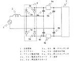
図1は、本発明の実施の形態1に係る直流電源装置の回路図である。交流電源1は、リアクトル2を介して、交流電源を全波整流するブリッジ整流回路3に接続されている。そのブリッジ整流回路3は、整流用ダイオード3a、3b、3c及び3dで構成されている。ブリッジ整流回路3の出力端には、直列に接続された2つの第一のコンデンサ4a及び4bが並列に接続されている。その2つの第一のコンデンサ4a及び4bの接続点は、ブリッジ整流回路3の交流入力端子の一方に接続されている。また、その直列に接続された2つの第一のコンデンサ4a及び4bの両端には、それぞれ逆流阻止手段5a及び5bを介して、直列に接続された2つの第二のコンデンサ6a及び6bが並列に接続されている。その2つの第二のコンデンサ6a及び6bの接続点は、ブリッジ整流回路3の交流入力端子のもう一方に接続されている。また、その直列に接続された2つの第二のコンデンサ6a及び6bの両端には、負荷7が並列に接続されている。
FIG. 1 is a circuit diagram of a DC power supply apparatus according to
図2、図3及び図4は図1の回路の動作を示す図である。
図2において、交流電源1が負のとき、交流電源1、整流用ダイオード3b、第一のコンデンサ4a、リアクトル2の順で電流が流れる(図2中破線)。すると、第一のコンデンサ4aに交流電源1の交流電圧の略ピーク値が充電される。次に、交流電源1が正のとき、交流電源1、リアクトル2、第一のコンデンサ4a、逆流阻止手段5a、第二のコンデンサ6aの順で電流が流れる(図2中実線)。すると、第二のコンデンサ6aには、交流電源1の交流電圧の略ピーク値と第一のコンデンサ4aの充電電圧が加算された電圧が充電される。第一のコンデンサ4aには交流電源1の交流電圧の略ピーク値が充電されているため、第二のコンデンサ6aには交流電源1の交流電圧のピーク値の略2倍の電圧が充電されることになる。
2, 3 and 4 are diagrams showing the operation of the circuit of FIG.
In FIG. 2, when the
また、図3において、交流電源1が正のとき、交流電源1、リアクトル2、第一のコンデンサ4b、整流用ダイオード3dの順で電流が流れる(図3中実線)。すると、第一のコンデンサ4bに交流電源1の交流電圧の略ピーク値が充電される。次に、交流電源1が負のとき、交流電源1、第二のコンデンサ6b、逆流阻止手段5b、第一のコンデンサ4b、リアクトル2の順で電流が流れる(図3中破線)。すると、第二のコンデンサ6bには、交流電源1の交流電圧の略ピーク値と第一のコンデンサ4bの充電電圧が加算された電圧が充電される。第一のコンデンサ4bには交流電源1の交流電圧の略ピーク値が充電されているため、第二のコンデンサ6bには交流電源1の交流電圧のピーク値の略2倍の電圧が充電されることになる。
In FIG. 3, when the
すると、図4に示すように、第二のコンデンサ6a及び6bには、それぞれ交流電源1の交流電圧のピーク値の略2倍の電圧が充電されており、その2つの第二のコンデンサ6a及び6bが直列に接続されているため、その両端から交流電源1の交流電圧のピーク値の略4倍の電圧が出力されることになる。
Then, as shown in FIG. 4, each of the
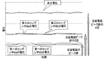
図5は、本発明の実施の形態1に係る電圧波形図である。第一のコンデンサ4a及び4bは交流電源1の交流電圧の略ピーク値に充電され、第二のコンデンサ6a及び6bは交流電源1の交流電圧のピーク値の略2倍に充電される。従って、出力電圧は交流電源1の交流電圧のピーク値の略4倍の電圧となる。ただし、接続される負荷7の容量が大きい場合には、出力電圧が交流電源1の交流電圧の4倍以下になる場合がある。
FIG. 5 is a voltage waveform diagram according to the first embodiment of the present invention. The
図6及び図7は、本発明の実施の形態1に係るその他の回路図例である。
第二のコンデンサ6a及び6bには交流電源1の交流電圧のピーク値の略2倍の電圧が充電されるため、交流電源1の交流電圧及び第一のコンデンサ4a及び4bの充電電圧に比べて電圧が高い状態になる。そのため、図1から図4に示すように逆流阻止手段5a及び5bが存在しないと、第二のコンデンサ6aから第一のコンデンサ4aに向かって、あるいは、第一のコンデンサ4bから第二のコンデンサ6bに向かって電流が逆流する恐れがある。
6 and 7 are other circuit diagram examples according to the first embodiment of the present invention.
Since the
そこで、図6に示されるように逆流阻止手段5a及び5bとしてダイオード8a及び8bが設けられることで、電流の逆流が防止される。
Therefore, as shown in FIG. 6, by providing the
しかし、ダイオード8a及び8bが使用された場合、電流がダイオード8a及び8bを順方向に流れた際の電圧降下による効率悪化が懸念される。そこで、図7に示されるように、ダイオード8a及び8bを短絡するようなダイオード短絡手段9a及び9bを設ける。そして、制御部51が、それらダイオード短絡手段9a及び9bを制御することにより、ダイオード8a及び8bを短絡することによって、電流はダイオード8a及び8bではなくダイオード短絡手段9a及び9bに流れるため、電圧降下による効率悪化が防止される。ここで、制御部51は、例えば、マイコン等の演算装置である。
However, when the
しかしながら、前述の通り、第二のコンデンサ6a及び6bには、交流電源1の交流電圧及び第一のコンデンサ4a及び4bの充電電圧より大きな電圧が充電されているため、電流の逆流が懸念される。そこで、制御部51が、電流がダイオード8a及び8bを正方向に流れるタイミングに、すなわち、ダイオード8a及び8bに逆方向電圧が印加されるタイミング以外に、ダイオード短絡手段9a及び9bを短絡を閉じ、ダイオード8a及び8bを短絡することで、ダイオード8a及び8bによって電流の逆流が防止されるとともに、電流がダイオード短絡手段9a及び9bを流れることにより電圧降下による効率悪化が防止される。
However, as described above, since the
ここで、ダイオード短絡手段9a及び9bについて、例えば、制御部51によって次のように動作させる。
第一の開閉手段10(後述の図8参照)及び第二の開閉手段11(後述の図9参照)の両方、又は片方が開放している場合は、第二のコンデンサ6a及び6bには電源電圧と同じ電圧が充電されるため、逆流は発生しない。このとき、制御部51が、ダイオード短絡手段9a及び9bを閉じ、ダイオード8a及び8bを短絡することによって、電流がダイオード8a及び8bを流れることによる電圧降下が防止される。一方、第一の開閉手段10及び第二の開閉手段11が両方閉じられている場合には、逆流する恐れがある。このとき、制御部51が、ダイオード短絡手段9a及び9bを開くことによって、逆流は防止される。
また、第二のコンデンサ6a及び6bの充放電のタイミングが既知である場合において、第二のコンデンサ6a及び6bが充電されている場合には、逆流は生じない。このとき、制御部51が、ダイオード短絡手段9a及び9bを閉じ、ダイオード8a及び8bを短絡することによって、上記と同様に、電圧降下が防止される。一方、第二のコンデンサ6a及び6bが放電されている場合には、逆流する恐れがある。このとき、制御部51が、ダイオード短絡手段9a及び9bを開くことによって、逆流は防止される。
Here, the diode short-circuit means 9a and 9b are operated by the
When both the first opening / closing means 10 (see FIG. 8 described later) and the second opening / closing means 11 (see FIG. 9 described later) or one of them is open, the
Further, in the case where the charging / discharging timing of the
以上の構成により、交流電源の交流電圧のピーク値の略4倍までの直流電圧が出力可能となる。また、例えば、実施の形態1に係る直流電源装置に、電動機を駆動するインバータが接続された場合、誘起電圧が高い電動機の使用が可能となり、高速域まで駆動することが可能となる。また、電動機やインバータに流れる電流を低減することができ、高効率化及び省エネルギー化が可能となる。
With the above configuration, a DC voltage up to about four times the peak value of the AC voltage of the AC power supply can be output. Further, for example, when an inverter that drives an electric motor is connected to the DC power supply device according to
なお、ダイオード短絡手段9a及び9bとして、機械式の開閉器、半導体によるスイッチング素子、あるいは、双方向スイッチが使用されても問題ないことは言うまでもない。このことは他の実施の形態も同様である。また、第二のコンデンサ6a及び6bには交流電源1の交流電圧のピーク値の略2倍の電圧が充電されるため、第一のコンデンサ4a及び4bの充電電圧に比べて電圧が高い状態になるので、第二のコンデンサ6a及び6bの耐圧を、第一のコンデンサ4a及び4bの耐圧よりも高いものにして、適式に選定することにより、コンデンサの故障を防止することができる。
なお、図1において、リアクトル2は、交流電源1に接続される構成のみでなく、図2及び図3におけるコンデンサへの充電経路を含めた全ての閉回路のそれぞれにリアクトル2が存在するように複数設置される構成としてもよい。
Needless to say, there is no problem even if a mechanical switch, a semiconductor switching element, or a bidirectional switch is used as the diode short-circuiting means 9a and 9b. The same applies to other embodiments. In addition, since the
In FIG. 1, the
実施の形態2.
図8は、実施の形態2に係る直流電源装置の回路図である。直列に接続された2つの第一のコンデンサ4a及び4bの接続点とブリッジ整流回路3の交流入力端子の一方との間に第一の開閉手段10が備えられている。そして、交流電源1の交流電圧のゼロ点を検出するゼロクロス検出手段81が、交流電源1と並列に接続されている。ゼロクロス検出手段81の出力側は、制御部51に接続されている。また、出力電圧を検出する出力電圧検出手段82が、直列に接続された2つの第二のコンデンサ6a及び6bの両端に接続されている。出力電圧検出手段82の出力側は、制御部51に接続されている。ゼロクロス検出手段81は、上記のように検出したゼロ点の信号を、制御部51に出力する。また、出力電圧検出手段82は、上記のように検出した出力電圧を、制御部51に出力する。上記の構成以外については、実施の形態1と同じ構成のため、実施の形態1との相違点を中心に説明する。また、ゼロクロス検出手段81の動作については、実施の形態4において後述する。
FIG. 8 is a circuit diagram of a DC power supply device according to the second embodiment. A first opening / closing means 10 is provided between the connection point of the two
制御部51によって第一の開閉手段10が閉じられた場合は、実施の形態1と同様の回路構成となり、交流電源1の交流電圧のピーク値の略4倍の電圧が出力されることになる。また、制御部51によって第一の開閉手段10が開かれた場合は、倍電圧整流回路となり、交流電源1の交流電圧のピーク値の略2倍の電圧が出力される構成となる。
When the first opening / closing means 10 is closed by the
また、制御部51が、第一の開閉手段10の開閉動作を繰り返すことにより、交流電源1の交流電圧のピーク値の略2倍から4倍までの間の電圧が出力可能となる。
Further, the
また、例えば、出力電圧検出手段82が出力電圧を検出し、制御部51が、その出力電圧を出力電圧検出手段82から受信して、出力電圧が所望の値になるよう第一の開閉手段10を動作させることにより、負荷7に最適な電圧を出力することも可能である。
In addition, for example, the output
さらに、制御部51が、第一の開閉手段10に対して、例えば、PWM(Pulse Width Modulation)制御によって、交流電源1の周波数より早い周波数で開閉させることで、交流電源1の交流電圧のピーク値の略2倍から4倍の電圧を出力することが可能となるだけでなく、入力電流を略正弦波化させることが可能となり、高力率状態にて動作するため、有効電力が増加する。PWM制御の動作の詳細は、実施の形態4において後述する。一般的に入力はブレーカ容量で制限されているため、増加した有効電力分だけ、直流電源装置に接続された負荷への入力電力を増加させることができ、負荷の出力を大きくすることができる。また、有効電力が増加するので無効電力が減少し、配電設備での受電容量の削減が実現でき、発電所にて発電しているエネルギーの有効利用に寄与することができる。また、入力電流が略正弦波化することにより、高調波成分が減少するため、JISやIECで定められている電源高調波規格にも適合可能である。
Further, the
さらに、制御部51が、第一の開閉手段10に対して、第二のコンデンサ6a及び6bからの電流の逆流が生じないように制御することにより、逆流阻止手段5a及び5bを省くことができ、低コストな直流電源装置を提供することが可能である。
Further, the
なお、第一の開閉手段10として、機械式の開閉器、半導体によるスイッチング素子、あるいは、双方向スイッチが使用されても問題ないことは言うまでもない。 Needless to say, there is no problem even if a mechanical switch, a semiconductor switching element, or a bidirectional switch is used as the first switching means 10.
実施の形態3.
図9は、実施の形態3に係る直流電源装置の回路図である。直列に接続された2つの第二のコンデンサ6a及び6bの接続点とブリッジ整流回路3の交流入力端子の一方との間に第二の開閉手段11が備えられている。そして、交流電源1の交流電圧のゼロ点を検出するゼロクロス検出手段81が、交流電源1と並列に接続されている。ゼロクロス検出手段81の出力側は、制御部51に接続されている。また、出力電圧を検出する出力電圧検出手段82が、直列に接続された2つの第二のコンデンサ6a及び6bの両端に接続されている。出力電圧検出手段82の出力側は、制御部51に接続されている。ゼロクロス検出手段81は、上記のように検出したゼロ点の信号を、制御部51に出力する。また、出力電圧検出手段82は、上記のように検出した出力電圧を、制御部51に出力する。上記の構成以外については、実施の形態1と同じ構成のため、実施の形態1との相違点を中心に説明する。また、ゼロクロス検出手段81の動作については、実施の形態4において後述する。
FIG. 9 is a circuit diagram of a DC power supply device according to the third embodiment. A second opening / closing means 11 is provided between a connection point between the two
制御部51によって第二の開閉手段11が閉じられた場合は、実施の形態1と同様の回路構成となり、交流電源1の交流電圧のピーク値の略4倍の電圧が出力されることになる。また、制御部51によって第二の開閉手段11が開かれた場合は、倍電圧整流回路となり、交流電源1の交流電圧のピーク値の略2倍の電圧が出力される構成となる。
When the second opening / closing means 11 is closed by the
また、制御部51が、第二の開閉手段11の開閉動作を繰り返すことにより、交流電源1の交流電圧のピーク値の略2倍から4倍までの間の電圧が出力可能となる。
Further, the
また、例えば、出力電圧検出手段82が出力電圧を検出し、制御部51が、その出力電圧を出力電圧検出手段82から受信して、出力電圧が所望の値になるよう第二の開閉手段11を動作させることにより、負荷7に最適な電圧を出力することも可能である。
In addition, for example, the output
さらに、制御部51が、第二の開閉手段11に対して、例えば、PWM(Pulse Width Modulation)制御によって、交流電源1の周波数より早い周波数で開閉させることで、交流電源1の交流電圧のピーク値の略2倍から4倍の電圧を出力することが可能となるだけでなく、入力電流を略正弦波化させることが可能となり、高力率状態にて動作するため、有効電力が増加する。PWM制御の動作の詳細は、実施の形態4において後述する。一般的に入力はブレーカ容量で制限されているため、増加した有効電力分だけ、直流電源装置に接続された負荷への入力電力を増加させることができ、負荷の出力を大きくすることができる。また、有効電力が増加するので無効電力が減少し、配電設備での受電容量の削減が実現でき、発電所にて発電しているエネルギーの有効利用に寄与することができる。また、入力電流が略正弦波化することにより、高調波成分が減少するため、JISやIECで定められている電源高調波規格にも適合可能である。
Further, the
さらに、制御部51が、第二の開閉手段11に対して、第二のコンデンサ6a及び6bからの電流の逆流が生じないように制御することにより、逆流阻止手段5a及び5bを省くことができ、低コストな直流電源装置を提供することが可能である。
Further, the
なお、第二の開閉手段11として、機械式の開閉器を用いても良く、半導体によるスイッチング素子、あるいは、双方向スイッチが使用されても問題ないことは言うまでもない。 Needless to say, a mechanical switch may be used as the second switching means 11, and there is no problem even if a semiconductor switching element or a bidirectional switch is used.
実施の形態4.
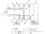
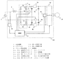
図10は、実施の形態4に係る直流電源装置の回路図である。直列に接続された2つの第一のコンデンサ4a及び4bの接続点とブリッジ整流回路3の交流入力端子の一方との間に第一の開閉手段10が備えられ、直列に接続された2つの第二のコンデンサ6a及び6bの接続点とブリッジ整流回路3の交流入力端子のもう一方との間に第二の開閉手段11が備えられている。そして、交流電源1の交流電圧のゼロ点を検出するゼロクロス検出手段81が、交流電源1と並列に接続されている。ゼロクロス検出手段81の出力側は、制御部51に接続されている。また、出力電圧を検出する出力電圧検出手段82が、直列に接続された2つの第二のコンデンサ6a及び6bの両端に接続されている。出力電圧検出手段82の出力側は、制御部51に接続されている。ゼロクロス検出手段81は、上記のように検出したゼロ点の信号を、制御部51に出力する。また、出力電圧検出手段82は、上記のように検出した出力電圧を、制御部51に出力する。上記の構成以外については、実施の形態1と同じ構成のため、実施の形態1との相違点を中心に説明する。
FIG. 10 is a circuit diagram of a DC power supply device according to the fourth embodiment. A first opening / closing means 10 is provided between a connection point between the two
制御部51によって第一の開閉手段10及び第二の開閉手段11が閉じられた場合は、実施の形態1と同様の回路構成となり、交流電源1の交流電圧のピーク値の略4倍の電圧が出力されることになる。また、制御部51によって第一の開閉手段10が開かれ、第二の開閉手段11が閉じられた場合、もしくは第一の開閉手段10が閉じられ、第二の開閉手段11が開かれた場合には、倍電圧整流回路となり、交流電源1の交流電圧のピーク値の略2倍の電圧が出力される構成となる。さらに、第一の開閉手段10及び第二の開閉手段11が開かれた場合には、全波整流回路となり、交流電源1の交流電圧のピーク値と略同じ電圧が出力可能となる。
When the first opening / closing means 10 and the second opening / closing means 11 are closed by the
また、制御部51が、第一の開閉手段10及び第二の開閉手段11の開閉動作を繰り返すことにより、交流電源1の交流電圧のピーク値の略1倍から4倍までの間の電圧が出力可能となる。
Further, the
また、例えば、出力電圧検出手段82が出力電圧を検出し、制御部51が、その出力電圧を出力電圧検出手段82から受信して、出力電圧が所望の値になるよう第一の開閉手段10及び第二の開閉手段11を動作させることにより、負荷7に最適な電圧を出力することも可能である。
In addition, for example, the output
さらに、制御部51が、第一の開閉手段10及び第二の開閉手段11に対して、例えば
、PWM(Pulse Width Modulation)制御によって、交流電源1の周波数より早い周波数で開閉させる動作例について、図11及び図12を参照して説明する。
Further, for an operation example in which the
図11は、実施の形態4に係る直流電源装置のPWM制御による動作例を示す制御ブロック図であり、図12は、そのPWM制御による動作例の状態を示すタイムチャートである。
図11で示されるように、制御部51が、直流電源装置の出力電圧を制御するための出力電圧の指令値をVdc*とし、図10に示される出力電圧検出手段82によって検出される直流電源装置の出力電圧をVdcとする。図11において、加算器51aは、このVdc*とVdcとの偏差ΔVdcを算出し、この偏差ΔVdcをPI制御器51cに出力する。この偏差ΔVdcを受信したPI制御器51cは、PI制御によって変調信号の振幅Aを求める。この振幅Aを受信した変調信号演算部51dは、振幅Aにsin(θ+φ)を乗じて、第一の開閉手段10を駆動するための変調信号Saを求める。ここで、θは交流電源1の電圧位相、φは任意に決定した位相である。また、加算器51bは、第二の開閉手段11を駆動するための変調信号Sbを、1からSaを引いたものとして求める。図12に示されるように、上記の変調信号Sa及びSbは、三角波のキャリア信号と比較され、第一の開閉手段10及び第二の開閉手段11に対する駆動信号が生成される。ここで、第一の開閉手段10に対する駆動信号は、変調信号Saよりキャリア信号の方が小さい場合には0(Low)、そして、大きい場合には1(High)として生成される。また、第二の開閉手段11に対する駆動信号は、変調信号Sbよりキャリア信号の方が小さい場合には1(High)、そして、大きい場合には0(Low)として生成される。
FIG. 11 is a control block diagram showing an operation example by PWM control of the DC power supply according to
As shown in FIG. 11, the
以上のような、PWM制御によって、交流電源1の交流電圧のピーク値の略1倍から4倍の電圧を出力することが可能となるだけでなく、入力電流を略正弦波化させることが可能となり、高力率状態にて動作するため、有効電力が増加する。一般的に入力はブレーカ容量で制限されているため、増加した有効電力分だけ、直流電源装置に接続された負荷への入力電力を増加させることができ、負荷の出力を大きくすることができる。また、有効電力が増加するので無効電力が減少し、配電設備での受電容量の削減が実現でき、発電所にて発電しているエネルギーの有効利用に寄与することができる。また、入力電流が略正弦波化することにより、高調波成分が減少するため、JISやIECで定められている電源高調波規格にも適合可能である。
With the PWM control as described above, it is possible not only to output a voltage approximately 1 to 4 times the peak value of the AC voltage of the
さらに、制御部51が、第一の開閉手段10及び第二の開閉手段11に対して、第二のコンデンサ6a及び6bからの電流の逆流が生じないように制御することにより、逆流阻止手段5a及び5bを省くことができ、低コストな直流電源装置を提供することが可能である。
Further, the
なお、第一の開閉手段10及び第二の開閉手段11として、機械式の開閉器、半導体によるスイッチング素子、あるいは、双方向スイッチが使用されても問題ないことは言うまでもない。
また、上記の変調信号Sa及びSbにおいて、第一の開閉手段10を駆動するために変調信号Sbが用いられ、第二の開閉手段11を駆動するために変調信号Saが用いられても同様のPWM制御が可能である。
また、上記のPWM制御において、実施の形態2に係る、第一の開閉手段10のみを備える直流電源装置については、変調信号Saによって得られる駆動信号のみによって、第一の開閉手段10に対しPWM制御が可能である。そして、実施の形態3に係る、第二の開閉手段11のみを備える直流電源装置についても、変調信号Saにより得られた駆動信号のみによって、第二の開閉手段11に対しPWM制御が可能である。
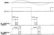
そして、図13に示されるように、交流電源1の交流電圧のゼロ点から、第一の開閉手段10については、Tdelay1の時間だけ遅らせた所からTon1の時間だけ、第二の開閉手段11については、Tdelay2の時間だけ遅らせた所からTon2の時間だけ、制御部51によって駆動される動作としても、上記と同様の効果を得ることができる。また、図13においては、第一の開閉手段10及び第二の開閉手段11について、ゼロ点から次のゼロ点までの間に、一回だけ駆動される動作が示されているが、複数回駆動される動作としてもよい。また、実施の形態2に係る、第一の開閉手段10のみを備える直流電源装置については、第一の開閉手段10に対して上記の制御が可能である。そして、実施の形態3に係る、第二の開閉手段11のみを備える直流電源装置についても、第二の開閉手段11に対して上記の制御が可能である。
Needless to say, a mechanical switch, a semiconductor switching element, or a bidirectional switch may be used as the first opening / closing means 10 and the second opening / closing means 11.
Further, in the modulation signals Sa and Sb, the modulation signal Sb is used for driving the first opening / closing means 10 and the modulation signal Sa is used for driving the second opening / closing means 11. PWM control is possible.
In the above-described PWM control, the DC power supply device including only the first opening / closing means 10 according to the second embodiment performs PWM for the first opening / closing means 10 only by the drive signal obtained from the modulation signal Sa. Control is possible. And also about the DC power supply device provided only with the 2nd opening-and-closing means 11 based on
Then, as shown in FIG. 13, for the first switching means 10 from the zero point of the AC voltage of the
実施の形態5.
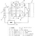
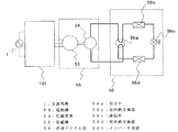
図14は、実施の形態5に係るインバータの接続図である。インバータ52は、実施の形態4に係る直流電源装置の出力側に、負荷として接続されており、また、制御部51の出力側にも接続されている。そして、インバータ52の出力側には、電動機53が接続されている。インバータ装置101は、実施の形態4に係る、交流電源1から電源を供給される直流電源装置と、インバータ52とで構成されている。図14において、インバータ装置101を構成する直流電源装置は、実施の形態4に係るものが示されているが、実施の形態1、2又は3に係る直流電源装置としてもよい。実施の形態5に係る直流電源装置から出力される直流電圧は、インバータ52に供給される。その直流電圧を供給されたインバータ52は、制御部51が出力した制御信号に従って、電動機53に駆動電流を供給し回転させる。
FIG. 14 is a connection diagram of an inverter according to the fifth embodiment. The
以上の構成により、誘起電圧の高い電動機53を駆動することが可能となるため、少ない電流で電動機が駆動可能となり、電動機53やインバータ52の損失低減による高効率化が可能である。そして、高い出力電圧を得ることが可能となるため、高速域まで電動機を回転させることが可能となり、性能を向上させることも可能となる。
以下に、他の装置に対する、インバータ装置101の適用例を示す。
With the above configuration, the
Below, the example of application of the
図15は、実施の形態5に係るインバータと、空気調和機の圧縮機との接続図である。インバータ装置101の出力側には電動機53が接続されており、その電動機53は、圧縮要素54に連結されている。圧縮機55は、電動機53と圧縮要素54から構成されている。冷凍サイクル部56は、四方弁56a、室内熱交換器56b、膨張弁56c及び室外熱交換器56dを含む態様で構成されている。空気調和機の内部を循環する冷媒の流路は、圧縮要素54から、四方弁56a、室内熱交換器56b、膨張弁56c、室外熱交換器56dを経由し、再び四方弁56aを経由して、圧縮要素54へ戻る態様で構成されている。インバータ装置101は、交流電源1より交流電圧の供給を受け、電動機53を回転させる。圧縮要素54は、電動機53が回転することによって、冷媒の圧縮動作を実行し、冷媒を冷凍サイクル部56内部で循環させる。
FIG. 15 is a connection diagram between the inverter according to
以上の構成により、図15で示される空気調和機においては、一年を通じて利用の多い低速回転及び低負荷という条件において消費電力の削減が可能となる。また、高速回転及び高負荷という条件における消費電力の削減及び冷房や暖房の能力向上が可能となり、省エネルギーで高性能な空気調和機を得ることができる。 With the above configuration, the air conditioner shown in FIG. 15 can reduce power consumption under conditions of low speed rotation and low load that are frequently used throughout the year. In addition, power consumption can be reduced under the conditions of high speed rotation and high load, and cooling and heating capabilities can be improved, and an energy-saving and high-performance air conditioner can be obtained.
図16は、前記インバータと、洗濯機の駆動用電動機との接続図である。水槽57は、洗濯機102内に設置され、その内部に、洗濯槽58が回転自在に設置されている。その洗濯槽58の底部には、攪拌翼59が回転自在に設置されている。水槽57の底部に設置された電動機53の回転軸は、水槽57及び攪拌翼59に連結されている。図示はしていないが、インバータ装置101が、電動機53に接続されており、洗濯機102の内部に搭載されている。インバータ装置101が、電動機53を回転制御することによって、洗濯槽58及び攪拌翼59が回転し、洗濯動作が実施される。
FIG. 16 is a connection diagram of the inverter and the electric motor for driving the washing machine. The
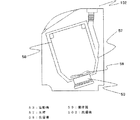
図17は、前記インバータと、洗濯乾燥機の駆動用電動機との接続図である。水槽60は、洗濯乾燥機103内に設置され、その内部に、回転ドラム61が回転自在に設置されている。水槽60の底部に設置された電動機53の回転軸は、回転ドラム61に連結されている。図示はしていないが、インバータ装置101が、電動機53に接続されており、洗濯乾燥機103の内部に搭載されている。インバータ装置101が、電動機53を回転制御することによって、回転ドラム61が回転し、洗濯及び乾燥動作が実施される。
FIG. 17 is a connection diagram of the inverter and the electric motor for driving the washing / drying machine. The
以上の構成により、図16及び図17で示される洗濯機や洗濯乾燥機においては、洗濯や乾燥運転といった低速回転及び高負荷な条件において、省エネルギー化が可能となる。また、脱水運転のように電動機を高速回転させる場合でも、大きな出力電圧が得られるため、さらに回転数を上げて脱水能力を高めることが可能である。従って、脱水時間が短くなることにより、顧客の満足度の高い洗濯機及び洗濯乾燥機を得ることができる。さらに、乾燥運転時には運転時間が短くなることにより、省エネルギーな洗濯乾燥機を得ることができる。 With the above configuration, the washing machine and the washing and drying machine shown in FIGS. 16 and 17 can save energy under conditions of low speed rotation and high load such as washing and drying operation. Further, even when the electric motor is rotated at a high speed as in the dehydration operation, a large output voltage can be obtained, so that it is possible to further increase the rotation speed and increase the dewatering capacity. Therefore, by reducing the dehydration time, it is possible to obtain a washing machine and a washing / drying machine with high customer satisfaction. Furthermore, an energy-saving washing and drying machine can be obtained by shortening the operation time during the drying operation.
以上、本発明に係る直流電源装置は、インバータに好適に用いられ、その適用例としては、圧縮機用インバータや送風機用インバータが挙げられる。圧縮機用インバータが搭載される例として、空気調和機、冷蔵庫、冷凍機、除湿機、給湯機が挙げられ、また、送風機用インバータが搭載される例として、換気扇、空気清浄機、加湿器が挙げられる。このように、本発明に係る直流電源装置の適用範囲は広く、産業上の利用可能性は大きい。 As described above, the DC power supply device according to the present invention is suitably used for an inverter, and examples of the application include an inverter for a compressor and an inverter for a blower. Examples of compressor inverters that are installed include air conditioners, refrigerators, refrigerators, dehumidifiers, and water heaters. Examples of fans that are equipped with inverters for fans are ventilation fans, air purifiers, and humidifiers. Can be mentioned. Thus, the application range of the DC power supply device according to the present invention is wide and the industrial applicability is great.
1 交流電源、2 リアクトル、3 ブリッジ整流回路、3a、3b、3c、3d 整流用ダイオード、4a、4b 第一のコンデンサ、5a、5b 逆流阻止手段、6a、6b 第二のコンデンサ、7 負荷、8a、8b ダイオード、9a、9b ダイオード短絡手段、10 第一の開閉手段、11 第二の開閉手段、51 制御部、51a、51b 加算器、51c PI制御器、51d 変調信号演算部、52 インバータ、53 電動機、54 圧縮要素、55 圧縮機、56 冷凍サイクル部、56a 四方弁、56b 室内熱交換器、56c 膨張弁、56d 室外熱交換器、57、60 水槽、58 洗濯槽、59 攪拌翼、61 回転ドラム、81 ゼロクロス検出手段、82 出力電圧検出手段、101 インバータ装置、102 洗濯機、103 洗濯乾燥機。 1 AC power source, 2 reactor, 3 bridge rectifier circuit, 3a, 3b, 3c, 3d rectifier diode, 4a, 4b first capacitor, 5a, 5b backflow prevention means, 6a, 6b second capacitor, 7 load, 8a , 8b Diode, 9a, 9b Diode short-circuiting means, 10 First switching means, 11 Second switching means, 51 Control section, 51a, 51b Adder, 51c PI controller, 51d Modulation signal calculation section, 52 Inverter, 53 Electric motor, 54 compression element, 55 compressor, 56 refrigeration cycle section, 56a four-way valve, 56b indoor heat exchanger, 56c expansion valve, 56d outdoor heat exchanger, 57, 60 water tank, 58 washing tub, 59 stirring blade, 61 rotations Drum, 81 Zero cross detection means, 82 Output voltage detection means, 101 Inverter device, 102 Washing machine, 1 3 washing and drying machine.
Claims (28)
前記整流回路の出力端に並列接続された、直列に接続された2つの第一のコンデンサと、
前記直列に接続された2つの第一のコンデンサの両端に接続された2つの逆流阻止手段を介して並列に接続された、直列に接続された2つの第二のコンデンサと、
を備え、
前記直列に接続された2つの第一のコンデンサの接続点と前記整流回路の交流入力端子の一方とが接続され、
前記直列に接続された2つの第二のコンデンサの接続点と前記整流回路の交流入力端子のもう一方とが接続され、
前記交流電源の交流電圧のピーク値の略4倍の電圧を、前記直列に接続された2つの第二のコンデンサの両端に並列に接続される負荷に出力する
ことを特徴とする直流電源装置。 A rectifier circuit for full-wave rectification of an AC power supply via a reactor;
Two first capacitors connected in series connected in parallel to the output of the rectifier circuit;
Two second capacitors connected in series connected in parallel via two backflow blocking means connected across the two first capacitors connected in series;
With
A connection point between the two first capacitors connected in series and one of the AC input terminals of the rectifier circuit are connected,
The connection point of the two second capacitors connected in series and the other of the AC input terminals of the rectifier circuit are connected,
A DC power supply apparatus, characterized in that a voltage approximately four times the peak value of the AC voltage of the AC power supply is output to a load connected in parallel across the two second capacitors connected in series.
前記整流回路の出力端に並列接続された、直列に接続された2つの第一のコンデンサと、
前記直列に接続された2つの第一のコンデンサの両端に接続された2つの逆流阻止手段を介して並列に接続された、直列に接続された2つの第二のコンデンサと、
前記直列に接続された2つの第一のコンデンサの接続点と前記整流回路の交流入力端子の一方との間に設けられた第一の開閉手段と、
前記第一の開閉手段の開閉動作を制御する制御手段と、
を備え、
前記直列に接続された2つの第二のコンデンサの接続点と前記整流回路の交流入力端子のもう一方とが接続され、
前記制御手段によって前記第一の開閉手段が操作されることにより、前記交流電源の交流電圧のピーク値の略2倍から略4倍の間の電圧を、前記直列に接続された2つの第二のコンデンサの両端に並列に接続される負荷に出力する
ことを特徴とする直流電源装置。 A rectifier circuit for full-wave rectification of an AC power supply via a reactor;
Two first capacitors connected in series connected in parallel to the output of the rectifier circuit;
Two second capacitors connected in series connected in parallel via two backflow blocking means connected across the two first capacitors connected in series;
First opening / closing means provided between a connection point of the two first capacitors connected in series and one of the AC input terminals of the rectifier circuit;
Control means for controlling the opening / closing operation of the first opening / closing means;
With
The connection point of the two second capacitors connected in series and the other of the AC input terminals of the rectifier circuit are connected,
When the first opening / closing means is operated by the control means, a voltage between about twice and about four times the peak value of the AC voltage of the AC power supply is applied to the two second connected in series. Output to a load connected in parallel across the capacitor.
前記整流回路の出力端に並列接続された、直列に接続された2つの第一のコンデンサと、
前記直列に接続された2つの第一のコンデンサの両端に接続された2つの逆流阻止手段を介して並列に接続された、直列に接続された2つの第二のコンデンサと、
前記直列に接続された2つの第二のコンデンサの接続点と前記整流回路の交流入力端子の一方との間に設けられた第二の開閉手段と、
前記第二の開閉手段の開閉動作を制御する制御手段と、
を備え、
前記直列に接続された2つの第一のコンデンサの接続点と前記整流回路の交流入力端子のもう一方とが接続され、
前記制御手段によって前記第二の開閉手段が操作されることにより、前記交流電源の交流電圧のピーク値の略2倍から略4倍の間の電圧を、前記直列に接続された2つの第二のコンデンサの両端に並列に接続される負荷に出力する
ことを特徴とする直流電源装置。 A rectifier circuit for full-wave rectification of an AC power supply via a reactor;
Two first capacitors connected in series connected in parallel to the output of the rectifier circuit;
Two second capacitors connected in series connected in parallel via two backflow blocking means connected across the two first capacitors connected in series;
A second opening / closing means provided between a connection point of the two second capacitors connected in series and one of the AC input terminals of the rectifier circuit;
Control means for controlling the opening and closing operation of the second opening and closing means;
With
A connection point between the two first capacitors connected in series and the other of the AC input terminals of the rectifier circuit are connected;
When the second opening / closing means is operated by the control means, a voltage between about 2 times and about 4 times the peak value of the AC voltage of the AC power supply is applied to the two second connected in series. Output to a load connected in parallel across the capacitor.
前記整流回路の出力端に並列接続された、直列に接続された2つの第一のコンデンサと、
前記直列に接続された2つの第一のコンデンサの両端に接続された2つの逆流阻止手段を介して並列に接続された、直列に接続された2つの第二のコンデンサと、
前記直列に接続された2つの第一のコンデンサの接続点と前記整流回路の交流入力端子の一方との間に設けられた第一の開閉手段と、
前記直列に接続された2つの第二のコンデンサの接続点と前記整流回路の交流入力端子のもう一方との間に設けられた第二の開閉手段と、
前記第一及び第二の開閉手段の開閉動作を制御する制御手段と、
を備え、
前記制御手段によって前記第一及び第二の開閉手段が操作されることにより、前記交流電源の交流電圧の略ピーク値から略4倍の間の電圧を、前記直列に接続された2つの第二のコンデンサの両端に並列に接続される負荷に出力する
ことを特徴とする直流電源装置。 A rectifier circuit for full-wave rectification of an AC power supply via a reactor;
Two first capacitors connected in series connected in parallel to the output of the rectifier circuit;
Two second capacitors connected in series connected in parallel via two backflow blocking means connected across the two first capacitors connected in series;
First opening / closing means provided between a connection point of the two first capacitors connected in series and one of the AC input terminals of the rectifier circuit;
A second opening / closing means provided between a connection point of the two second capacitors connected in series and the other of the AC input terminals of the rectifier circuit;
Control means for controlling the opening and closing operations of the first and second opening and closing means;
With
By operating the first and second opening / closing means by the control means, a voltage between about four times the peak value of the AC voltage of the AC power supply is supplied to the two second connected in series. Output to a load connected in parallel across the capacitor.
ことを特徴とする請求項1〜請求項4のいずれかに記載の直流電源装置。 The DC power supply device according to any one of claims 1 to 4, wherein the backflow prevention means is a diode.
ことを特徴とする請求項5記載の直流電源装置。 6. The DC power supply device according to claim 5, further comprising diode short-circuit means connected in parallel to the diode.
ことを特徴とする請求項6に記載の直流電源装置。 The DC power supply device according to claim 6, wherein the control unit short-circuits the diode by the diode short-circuit unit except for a timing at which a reverse voltage is applied to the diode.
ことを特徴とする請求項6又は請求項7記載の直流電源装置。 The DC power supply device according to claim 6 or 7, wherein the diode short-circuiting means is a switching element made of a semiconductor.
ことを特徴とする請求項6又は請求項7記載の直流電源装置。 The DC power supply device according to claim 6 or 7, wherein the diode short-circuiting means is a mechanical switch.
ことを特徴とする請求項6又は請求項7記載の直流電源装置。 The DC power supply device according to claim 6 or 7, wherein the diode short-circuiting means is a bidirectional switch.
前記整流回路の出力端に並列接続された、直列に接続された2つの第一のコンデンサと、
前記直列に接続された2つの第一のコンデンサの両端に並列に接続された、直列に接続された2つの第二のコンデンサと、
前記直列に接続された2つの第一のコンデンサの接続点と前記整流回路の交流入力端子の一方との間に設けられた第一の開閉手段と、
前記第一の開閉手段の開閉動作を制御する制御手段と、
を備え、
前記直列に接続された2つの第二のコンデンサの接続点と前記整流回路の交流入力端子のもう一方とが接続され、
前記制御手段によって前記第一の開閉手段が操作されることにより、前記交流電源の交流電圧のピーク値の略2倍から略4倍の間の電圧を、前記直列に接続された2つの第二のコンデンサの両端に並列に接続される負荷に出力する
ことを特徴とする直流電源装置。 A rectifier circuit for full-wave rectification of an AC power supply via a reactor;
Two first capacitors connected in series connected in parallel to the output of the rectifier circuit;
Two second capacitors connected in series connected in parallel across the two first capacitors connected in series;
First opening / closing means provided between a connection point of the two first capacitors connected in series and one of the AC input terminals of the rectifier circuit;
Control means for controlling the opening / closing operation of the first opening / closing means;
With
The connection point of the two second capacitors connected in series and the other of the AC input terminals of the rectifier circuit are connected,
When the first opening / closing means is operated by the control means, a voltage between about twice and about four times the peak value of the AC voltage of the AC power supply is applied to the two second connected in series. Output to a load connected in parallel across the capacitor.
前記整流回路の出力端に並列接続された、直列に接続された2つの第一のコンデンサと、
前記直列に接続された2つの第一のコンデンサの両端に並列に接続された、直列に接続された2つの第二のコンデンサと、
前記直列に接続された2つの第二のコンデンサの接続点と前記整流回路の交流入力端子の一方との間に設けられた第二の開閉手段と、
前記第二の開閉手段の開閉動作を制御する制御手段と、
を備え、
前記直列に接続された2つの第一のコンデンサの接続点と前記整流回路の交流入力端子のもう一方とが接続され、
前記制御手段によって前記第二の開閉手段が操作されることにより、前記交流電源の交流電圧のピーク値の略2倍から略4倍の間の電圧を、前記直列に接続された2つの第二のコンデンサの両端に並列に接続される負荷に出力する
ことを特徴とする直流電源装置。 A rectifier circuit for full-wave rectification of an AC power supply via a reactor;
Two first capacitors connected in series connected in parallel to the output of the rectifier circuit;
Two second capacitors connected in series connected in parallel across the two first capacitors connected in series;
A second opening / closing means provided between a connection point of the two second capacitors connected in series and one of the AC input terminals of the rectifier circuit;
Control means for controlling the opening and closing operation of the second opening and closing means;
With
A connection point between the two first capacitors connected in series and the other of the AC input terminals of the rectifier circuit are connected;
When the second opening / closing means is operated by the control means, a voltage between about 2 times and about 4 times the peak value of the AC voltage of the AC power supply is applied to the two second connected in series. Output to a load connected in parallel across the capacitor.
前記整流回路の出力端に並列接続された、直列に接続された2つの第一のコンデンサと、
前記直列に接続された2つの第一のコンデンサの両端に並列に接続された、直列に接続された2つの第二のコンデンサと、
前記直列に接続された2つの第一のコンデンサの接続点と前記整流回路の交流入力端子の一方との間に設けられた第一の開閉手段と、
前記直列に接続された2つの第二のコンデンサの接続点と前記整流回路の交流入力端子のもう一方との間に設けられた第二の開閉手段と、
前記第一及び第二の開閉手段の開閉動作を制御する制御手段と、
を備え、
前記制御手段によって前記第一及び第二の開閉手段が操作されることにより、前記交流電源の交流電圧の略ピーク値から略4倍の間の電圧を、前記直列に接続された2つの第二のコンデンサの両端に並列に接続される負荷に出力する
ことを特徴とする直流電源装置。 A rectifier circuit for full-wave rectification of an AC power supply via a reactor;
Two first capacitors connected in series connected in parallel to the output of the rectifier circuit;
Two second capacitors connected in series connected in parallel across the two first capacitors connected in series;
First opening / closing means provided between a connection point of the two first capacitors connected in series and one of the AC input terminals of the rectifier circuit;
A second opening / closing means provided between a connection point of the two second capacitors connected in series and the other of the AC input terminals of the rectifier circuit;
Control means for controlling the opening and closing operations of the first and second opening and closing means;
With
By operating the first and second opening / closing means by the control means, a voltage between about four times the peak value of the AC voltage of the AC power supply is supplied to the two second connected in series. Output to a load connected in parallel across the capacitor.
ことを特徴とする請求項2〜請求項4、請求項11〜請求項13のいずれかに記載の直流電源装置。 The DC power supply device according to any one of claims 2 to 4, and 11 to 13, wherein the opening / closing means is a switching element made of a semiconductor.
ことを特徴とする請求項2〜請求項4、請求項11〜請求項13のいずれかに記載の直流電源装置。 The DC power supply device according to any one of claims 2 to 4, and 11 to 13, wherein the opening / closing means is a mechanical switch.
ことを特徴とする請求項2〜請求項4、請求項11〜請求項13のいずれかに記載の直流電源装置。 The DC power supply device according to any one of claims 2 to 4, and 11 to 13, wherein the opening / closing means is a bidirectional switch.
ことを特徴とする請求項1〜請求項16のいずれかに記載の直流電源装置。 The DC power supply device according to any one of claims 1 to 16, wherein the second capacitor has a higher withstand voltage than the first capacitor.
ことを特徴とする請求項2、請求項4、請求項11又は請求項13記載の直流電源装置。 The DC power supply apparatus according to claim 2, 4, 11, or 13, wherein the control means opens and closes the first opening / closing means at a frequency higher than the frequency of the AC power supply. .
ことを特徴とする請求項3、請求項4、請求項12又は請求項13記載の直流電源装置。 The DC power supply device according to claim 3, 4, 12, or 13, wherein the control means opens and closes the second opening / closing means at a frequency higher than the frequency of the AC power supply. .
前記直流電源装置の出力電圧を検出する出力電圧検出手段と、
を備え、
前記制御手段は、前記ゼロクロス検出手段によって検出されたゼロクロス検出信号、及び、前記出力電圧検出手段によって検出された出力電圧に基づいて、前記第一の開閉手段をPWM制御によって開閉動作させる
ことを特徴とする請求項18記載の直流電源装置。 Zero-cross detection means for detecting a zero point of the AC voltage of the AC power supply;
Output voltage detecting means for detecting an output voltage of the DC power supply device;
With
The control means opens and closes the first opening / closing means by PWM control based on the zero-cross detection signal detected by the zero-cross detection means and the output voltage detected by the output voltage detection means. The DC power supply device according to claim 18.
前記直流電源装置の出力電圧を検出する出力電圧検出手段と、
を備え、
前記制御手段は、前記ゼロクロス検出手段によって検出されたゼロクロス検出信号、及び、前記出力電圧検出手段によって検出された出力電圧に基づいて、前記第二の開閉手段をPWM制御によって開閉動作させる
ことを特徴とする請求項19記載の直流電源装置。 Zero-cross detection means for detecting a zero point of the AC voltage of the AC power supply;
Output voltage detecting means for detecting an output voltage of the DC power supply device;
With
The control means opens and closes the second opening / closing means by PWM control based on the zero-cross detection signal detected by the zero-cross detection means and the output voltage detected by the output voltage detection means. The DC power supply device according to claim 19.
前記制御手段は、前記ゼロクロス検出手段によって検出されたゼロ点から、次に検出されたゼロ点までの間に、前記第一の開閉手段を1回又は複数回、開閉動作させる
ことを特徴とする請求項2、請求項4、請求項11又は請求項13記載の直流電源装置。 Comprising zero-cross detection means for detecting a zero point of the AC voltage of the AC power source;
The control means opens or closes the first opening / closing means one or more times between a zero point detected by the zero-cross detection means and a next detected zero point. The DC power supply device according to claim 2, claim 4, claim 11 or claim 13.
前記制御手段は、前記ゼロクロス検出手段によって検出されたゼロ点から、次に検出されたゼロ点までの間に、前記第二の開閉手段を1回又は複数回、開閉動作させる
ことを特徴とする請求項3、請求項4、請求項12又は請求項13記載の直流電源装置。 Comprising zero-cross detection means for detecting a zero point of the AC voltage of the AC power source;
The control means opens or closes the second opening / closing means one or more times between a zero point detected by the zero-cross detection means and a next detected zero point. The DC power supply device according to claim 3, claim 4, claim 12 or claim 13.
ことを特徴とする請求項1〜請求項23のいずれかに記載の直流電源装置。 The DC power supply device according to any one of claims 1 to 23, wherein a reactor is provided for each charging path to each of the capacitors instead of the reactor connected to the AC power supply.
Priority Applications (1)
| Application Number | Priority Date | Filing Date | Title |
|---|---|---|---|
| JP2008190835A JP4889694B2 (en) | 2008-07-24 | 2008-07-24 | DC power supply device, inverter device including the same, air conditioner including the inverter device, washing machine, and washing and drying machine |
Applications Claiming Priority (1)
| Application Number | Priority Date | Filing Date | Title |
|---|---|---|---|
| JP2008190835A JP4889694B2 (en) | 2008-07-24 | 2008-07-24 | DC power supply device, inverter device including the same, air conditioner including the inverter device, washing machine, and washing and drying machine |
Publications (2)
| Publication Number | Publication Date |
|---|---|
| JP2010029048A true JP2010029048A (en) | 2010-02-04 |
| JP4889694B2 JP4889694B2 (en) | 2012-03-07 |
Family
ID=41734312
Family Applications (1)
| Application Number | Title | Priority Date | Filing Date |
|---|---|---|---|
| JP2008190835A Active JP4889694B2 (en) | 2008-07-24 | 2008-07-24 | DC power supply device, inverter device including the same, air conditioner including the inverter device, washing machine, and washing and drying machine |
Country Status (1)
| Country | Link |
|---|---|
| JP (1) | JP4889694B2 (en) |
Cited By (4)
| Publication number | Priority date | Publication date | Assignee | Title |
|---|---|---|---|---|
| JP2013093924A (en) * | 2011-10-24 | 2013-05-16 | Mitsubishi Electric Corp | Dc power supply device, motor drive device having the same, and air conditioner, washing machine and washing and drying machine having the motor drive device |
| WO2015083244A1 (en) * | 2013-12-03 | 2015-06-11 | 三菱電機株式会社 | Power conversion device, motor drive device equipped with said power conversion device, fan and compressor equipped with said motor drive device, air conditioner, refrigerator, and freezer equipped with said fan and said compressor |
| US9948203B2 (en) | 2011-10-28 | 2018-04-17 | Mitsubishi Electric Corporation | Direct-current power supply device and electric motor driving device |
| JP2018078756A (en) * | 2016-11-11 | 2018-05-17 | 日立ジョンソンコントロールズ空調株式会社 | Power conversion device, and air conditioner using the same |
Citations (7)
| Publication number | Priority date | Publication date | Assignee | Title |
|---|---|---|---|---|
| JPS6373897A (en) * | 1986-09-11 | 1988-04-04 | Toshiba Corp | Variable speed operation device of motor |
| JPH1094265A (en) * | 1996-09-17 | 1998-04-10 | Toshiba Corp | Motor control circuit |
| JP2003009535A (en) * | 2001-04-17 | 2003-01-10 | Matsushita Electric Ind Co Ltd | Power supply |
| JP2003143856A (en) * | 2001-08-31 | 2003-05-16 | Vlt Corp | Passive control of harmonic from ac input through rectifying circuit |
| JP2005065435A (en) * | 2003-08-18 | 2005-03-10 | Matsushita Electric Ind Co Ltd | Power supply device |
| JP2008017627A (en) * | 2006-07-06 | 2008-01-24 | Matsushita Electric Ind Co Ltd | Power supply unit and air conditioner therewith |
| JP2008086107A (en) * | 2006-09-27 | 2008-04-10 | Matsushita Electric Ind Co Ltd | Motor drive controller |
-
2008
- 2008-07-24 JP JP2008190835A patent/JP4889694B2/en active Active
Patent Citations (7)
| Publication number | Priority date | Publication date | Assignee | Title |
|---|---|---|---|---|
| JPS6373897A (en) * | 1986-09-11 | 1988-04-04 | Toshiba Corp | Variable speed operation device of motor |
| JPH1094265A (en) * | 1996-09-17 | 1998-04-10 | Toshiba Corp | Motor control circuit |
| JP2003009535A (en) * | 2001-04-17 | 2003-01-10 | Matsushita Electric Ind Co Ltd | Power supply |
| JP2003143856A (en) * | 2001-08-31 | 2003-05-16 | Vlt Corp | Passive control of harmonic from ac input through rectifying circuit |
| JP2005065435A (en) * | 2003-08-18 | 2005-03-10 | Matsushita Electric Ind Co Ltd | Power supply device |
| JP2008017627A (en) * | 2006-07-06 | 2008-01-24 | Matsushita Electric Ind Co Ltd | Power supply unit and air conditioner therewith |
| JP2008086107A (en) * | 2006-09-27 | 2008-04-10 | Matsushita Electric Ind Co Ltd | Motor drive controller |
Cited By (8)
| Publication number | Priority date | Publication date | Assignee | Title |
|---|---|---|---|---|
| JP2013093924A (en) * | 2011-10-24 | 2013-05-16 | Mitsubishi Electric Corp | Dc power supply device, motor drive device having the same, and air conditioner, washing machine and washing and drying machine having the motor drive device |
| US9948203B2 (en) | 2011-10-28 | 2018-04-17 | Mitsubishi Electric Corporation | Direct-current power supply device and electric motor driving device |
| WO2015083244A1 (en) * | 2013-12-03 | 2015-06-11 | 三菱電機株式会社 | Power conversion device, motor drive device equipped with said power conversion device, fan and compressor equipped with said motor drive device, air conditioner, refrigerator, and freezer equipped with said fan and said compressor |
| CN105765851A (en) * | 2013-12-03 | 2016-07-13 | 三菱电机株式会社 | Power conversion device, motor drive device equipped with said power conversion device, fan and compressor equipped with said motor drive device, air conditioner, refrigerator, and freezer equipped with said fan and said compressor |
| JPWO2015083244A1 (en) * | 2013-12-03 | 2017-03-16 | 三菱電機株式会社 | Power conversion apparatus, motor drive apparatus including the same, blower including the same, compressor, air conditioner including them, refrigerator, and refrigerator |
| US9780717B2 (en) | 2013-12-03 | 2017-10-03 | Mitsubishi Electric Corporation | Power conversion device, motor driving device including power conversion device, blower and compressor including motor driving device, and air conditioner, refrigerator, and freezer including blower and compressor |
| CN105765851B (en) * | 2013-12-03 | 2018-09-04 | 三菱电机株式会社 | Power inverter, motor drive, air blower, compressor, air conditioner and refrigerator |
| JP2018078756A (en) * | 2016-11-11 | 2018-05-17 | 日立ジョンソンコントロールズ空調株式会社 | Power conversion device, and air conditioner using the same |
Also Published As
| Publication number | Publication date |
|---|---|
| JP4889694B2 (en) | 2012-03-07 |
Similar Documents
| Publication | Publication Date | Title |
|---|---|---|
| AU2008360120B2 (en) | AC-DC converter, AC-DC converter control method, motor driving device, compressor driving device, air conditioner, and heat pump-type hot-water supply device | |
| US9580858B2 (en) | Motor control device, air conditioner, washing machine and refrigerator | |
| JP4969653B2 (en) | AC / DC converter, compressor driving device using the same, and air conditioner | |
| JP5520119B2 (en) | DC power supply device, inverter drive device, and air conditioner using the same | |
| KR100639451B1 (en) | Motor drive apparatus, compressor, air conditionor, refrigerator, elecric washing machine, electric cleaner, electric dryer and heat pump water heater | |
| JP5674959B2 (en) | DC power supply device and motor drive device | |
| WO2013046454A1 (en) | Heat pump device, heat pump system, and inverter control method | |
| JP2012196142A (en) | Motor drive control device, compressor, air blower, air conditioner, and refrigerator or freezer | |
| WO2012104889A1 (en) | Backflow preventing means, power conversion apparatus, and freezing air conditioning apparatus | |
| JPWO2015056340A1 (en) | DC power supply, motor drive, air conditioner and refrigerator | |
| JP2008541683A (en) | Variable speed drive for cooling systems | |
| JP5769764B2 (en) | AC / DC converter, motor drive, compressor drive, air conditioner, heat pump water heater | |
| JP4889694B2 (en) | DC power supply device, inverter device including the same, air conditioner including the inverter device, washing machine, and washing and drying machine | |
| JP2017112776A (en) | Converter device, drive control device, motor, and compressor | |
| JP2011010432A (en) | Motor drive device | |
| JP4679848B2 (en) | Motor drive device | |
| JP2008061411A (en) | Power conversion device | |
| CN113315448A (en) | SPIM motor drive circuit and method | |
| WO2021048895A1 (en) | Compressor drive device, and air conditioning device | |
| CN215120633U (en) | SPIM motor drive circuit | |
| JP6173488B2 (en) | Inverter device and air conditioner using inverter device | |
| CN215268114U (en) | SPIM motor drive circuit | |
| US11699972B2 (en) | Variable speed motor drive with integrated motor heating systems and methods | |
| JP5916830B2 (en) | DC power supply device and motor drive device | |
| JP2005083683A (en) | Refrigerator and its operation control method |
Legal Events
| Date | Code | Title | Description |
|---|---|---|---|
| A977 | Report on retrieval |
Free format text: JAPANESE INTERMEDIATE CODE: A971007 Effective date: 20110620 |
|
| A131 | Notification of reasons for refusal |
Free format text: JAPANESE INTERMEDIATE CODE: A131 Effective date: 20110705 |
|
| A521 | Request for written amendment filed |
Free format text: JAPANESE INTERMEDIATE CODE: A523 Effective date: 20110830 |
|
| TRDD | Decision of grant or rejection written | ||
| A01 | Written decision to grant a patent or to grant a registration (utility model) |
Free format text: JAPANESE INTERMEDIATE CODE: A01 Effective date: 20111115 |
|
| A01 | Written decision to grant a patent or to grant a registration (utility model) |
Free format text: JAPANESE INTERMEDIATE CODE: A01 |
|
| A61 | First payment of annual fees (during grant procedure) |
Free format text: JAPANESE INTERMEDIATE CODE: A61 Effective date: 20111213 |
|
| R150 | Certificate of patent or registration of utility model |
Ref document number: 4889694 Country of ref document: JP Free format text: JAPANESE INTERMEDIATE CODE: R150 Free format text: JAPANESE INTERMEDIATE CODE: R150 |
|
| FPAY | Renewal fee payment (event date is renewal date of database) |
Free format text: PAYMENT UNTIL: 20141222 Year of fee payment: 3 |
|
| R250 | Receipt of annual fees |
Free format text: JAPANESE INTERMEDIATE CODE: R250 |
|
| R250 | Receipt of annual fees |
Free format text: JAPANESE INTERMEDIATE CODE: R250 |
|
| R250 | Receipt of annual fees |
Free format text: JAPANESE INTERMEDIATE CODE: R250 |
|
| R250 | Receipt of annual fees |
Free format text: JAPANESE INTERMEDIATE CODE: R250 |
|
| R250 | Receipt of annual fees |
Free format text: JAPANESE INTERMEDIATE CODE: R250 |
|
| R250 | Receipt of annual fees |
Free format text: JAPANESE INTERMEDIATE CODE: R250 |
|
| R250 | Receipt of annual fees |
Free format text: JAPANESE INTERMEDIATE CODE: R250 |
|
| R250 | Receipt of annual fees |
Free format text: JAPANESE INTERMEDIATE CODE: R250 |
|
| R250 | Receipt of annual fees |
Free format text: JAPANESE INTERMEDIATE CODE: R250 |