JP2010023489A - Printing head - Google Patents
Printing head Download PDFInfo
- Publication number
- JP2010023489A JP2010023489A JP2009125607A JP2009125607A JP2010023489A JP 2010023489 A JP2010023489 A JP 2010023489A JP 2009125607 A JP2009125607 A JP 2009125607A JP 2009125607 A JP2009125607 A JP 2009125607A JP 2010023489 A JP2010023489 A JP 2010023489A
- Authority
- JP
- Japan
- Prior art keywords
- plate
- recording head
- element substrate
- recording
- ink
- Prior art date
- Legal status (The legal status is an assumption and is not a legal conclusion. Google has not performed a legal analysis and makes no representation as to the accuracy of the status listed.)
- Granted
Links
Images


Classifications
-
- B—PERFORMING OPERATIONS; TRANSPORTING
- B41—PRINTING; LINING MACHINES; TYPEWRITERS; STAMPS
- B41J—TYPEWRITERS; SELECTIVE PRINTING MECHANISMS, i.e. MECHANISMS PRINTING OTHERWISE THAN FROM A FORME; CORRECTION OF TYPOGRAPHICAL ERRORS
- B41J2/00—Typewriters or selective printing mechanisms characterised by the printing or marking process for which they are designed
- B41J2/005—Typewriters or selective printing mechanisms characterised by the printing or marking process for which they are designed characterised by bringing liquid or particles selectively into contact with a printing material
- B41J2/01—Ink jet
- B41J2/17—Ink jet characterised by ink handling
- B41J2/175—Ink supply systems ; Circuit parts therefor
- B41J2/17503—Ink cartridges
- B41J2/1752—Mounting within the printer
-
- B—PERFORMING OPERATIONS; TRANSPORTING
- B41—PRINTING; LINING MACHINES; TYPEWRITERS; STAMPS
- B41J—TYPEWRITERS; SELECTIVE PRINTING MECHANISMS, i.e. MECHANISMS PRINTING OTHERWISE THAN FROM A FORME; CORRECTION OF TYPOGRAPHICAL ERRORS
- B41J2/00—Typewriters or selective printing mechanisms characterised by the printing or marking process for which they are designed
- B41J2/005—Typewriters or selective printing mechanisms characterised by the printing or marking process for which they are designed characterised by bringing liquid or particles selectively into contact with a printing material
- B41J2/01—Ink jet
- B41J2/17—Ink jet characterised by ink handling
- B41J2/175—Ink supply systems ; Circuit parts therefor
- B41J2/17503—Ink cartridges
- B41J2/17553—Outer structure
Abstract
Description
本発明は、記録ヘッドに関し、特に記録ヘッドの記録素子基板が接合される支持部材に樹脂材料を用いている記録ヘッドに関する。 The present invention relates to a recording head, and more particularly to a recording head using a resin material for a support member to which a recording element substrate of the recording head is bonded.
インクジェット方式による記録技術は、ランニングコストが安く、静かな記録方法として知られている。インクジェット記録装置をより安価に提供するためには、コスト上占める割合が高い、インク滴を吐出する記録ヘッドの低価格化を進めることが効果的である。インクを吐出するためのチップである記録素子基板は、記録ヘッドが有する面に高精度に位置決めされ、貼り付けられて固定される。低価格化を進めた記録ヘッドでは、記録素子基板が貼り付けられて固定される貼り付け面が樹脂性部材で構成されている場合が多い。これは、樹脂性部材以外の部材、例えばセラミック部材で記録素子基板の貼り付け面を構成するよりも、射出成形技術を用いて、低コストで記録ヘッドを生産することが可能であるためである。 The ink jet recording technique is known as a quiet recording method with a low running cost. In order to provide an inkjet recording apparatus at a lower cost, it is effective to reduce the cost of a recording head that ejects ink droplets, which has a high cost share. A recording element substrate, which is a chip for ejecting ink, is positioned with high accuracy on the surface of the recording head, and is fixed by being attached. In a recording head whose cost has been reduced, the attachment surface to which the recording element substrate is attached and fixed is often made of a resinous member. This is because it is possible to produce a recording head at a low cost by using an injection molding technique, rather than using a member other than a resinous member, for example, a ceramic member to form the attachment surface of the recording element substrate. .
ところで、記録ヘッドをインクジェット記録装置に取り付ける際に、高品位な記録品質を確保するために、取り付け基準面から記録素子基板のインクが吐出するオリフィスまでの寸法が精度よく維持管理されていることが求められる。その為、樹脂性部材の記録素子基板の貼り付け面には高い平面性が必要となる。その実現には成形樹脂の成形収縮率を均一にすることが望ましい。このため、記録素子基板が貼り付けられる支持部材の板状部の厚みは出来るだけ同じにすることが必要となる。またコストダウンを進める上で、同じ樹脂性部材で構成される支持部材により、インクを記録素子基板まで供給するインク流路や、インク中のゴミを取り除くフィルタの取り付け部などの形状を形成していることが多い。このような場合、記録素子基板が貼り付けられる支持部材の板状部の肉厚が厚くなる場合がある。なお、一般的に、射出成形により形成される樹脂部品の厚肉の部位の表面には、ヒケと呼ばれる凹みが発生することがある。このような凹みが記録素子基板の貼り付け面に発生しないように、記録素子基板の貼り付け面の裏面側に空洞部を形成し、貼り付け面の肉厚を軽減することにより、記録素子基板が貼り付けられる支持部材の板状部の厚みを均一にすることができる。このような構成の記録ヘッドは特許文献1に開示されている。 By the way, when the recording head is attached to the ink jet recording apparatus, in order to ensure high-quality recording quality, the dimension from the attachment reference plane to the orifice from which the ink on the recording element substrate is ejected is accurately maintained and managed. Desired. For this reason, high flatness is required on the bonding surface of the recording element substrate of the resin member. In order to realize this, it is desirable to make the molding shrinkage of the molding resin uniform. For this reason, it is necessary to make the thickness of the plate-like portion of the support member to which the recording element substrate is attached the same as possible. In order to further reduce costs, the support member made of the same resinous member is used to form shapes such as an ink flow path for supplying ink to the recording element substrate and a filter mounting portion for removing dust in the ink. There are many. In such a case, the thickness of the plate-like portion of the support member to which the recording element substrate is attached may increase. In general, a dent called a sink may occur on the surface of a thick part of a resin part formed by injection molding. A recording element substrate is formed by forming a cavity on the back side of the recording element substrate attachment surface to reduce the thickness of the attachment surface so that such a dent does not occur on the recording element substrate attachment surface. The thickness of the plate-like portion of the support member to which the is attached can be made uniform. A recording head having such a configuration is disclosed in Patent Document 1.
しかしながら、上述の記録ヘッドは、空洞部が形成されているため、空洞部を構成する壁の物理的な強度が低下する。 However, since the above-described recording head is formed with the cavity, the physical strength of the walls constituting the cavity is reduced.
したがって、空洞部が形成された記録ヘッドが記録装置に取り付けられる際に、誤って高所から落下して、前述の記録ヘッドの物理的な強度が弱い部分に衝撃を受けた場合、記録ヘッドに設けられた記録素子基板が変形して、記録不良を引き起こすことがある。 Therefore, when a recording head in which a hollow portion is formed is attached to the recording apparatus, if the recording head is accidentally dropped from a high place and an impact is applied to a portion where the physical strength of the recording head is weak, the recording head The provided recording element substrate may be deformed to cause a recording failure.
具体的には、落下した記録ヘッドが床等に衝突した際、支持部材の記録素子基板の貼り付け面が、衝突した衝撃により変形することにより記録素子基板が破損することがある。その場合、記録素子基板は接着剤や記録素子基板の周囲を封止する封止剤により支持部材に貼り付けられて接合されているため、その変形は接着剤や記録素子基板の周囲の封止剤を介して記録素子基板をも変形させることになる。このように記録素子基板が変形することは、記録品位に影響を与えるため好ましくない。 Specifically, when the dropped recording head collides with the floor or the like, the recording element substrate may be damaged due to deformation of the attachment surface of the recording element substrate of the support member due to the impact. In that case, since the recording element substrate is bonded and bonded to the support member with an adhesive or a sealing agent that seals the periphery of the recording element substrate, the deformation is sealed around the adhesive or the recording element substrate. The recording element substrate is also deformed through the agent. Such deformation of the recording element substrate is not preferable because it affects the recording quality.
特に、記録素子基板に、記録素子基板を貫通する矩形状のインク供給口が設けられている場合は、記録ヘッドに与えられた衝撃により記録素子基板が変形すると、さらに記録品位に影響を及ぼすことがある。このインク供給口は異方性エッチング加工法により形成されており、隅部を有する。したがって、前述した記録素子基板の変形は、インク供給口の隅部へ集中し、変形による隅部への応力が過大になると記録素子基板にクラックが発生することがある。記録素子基板のクラックは記録素子基板内部の配線等を切断し、記録不良を引き起こす場合がある。 In particular, when the recording element substrate is provided with a rectangular ink supply port penetrating the recording element substrate, the recording quality is further affected if the recording element substrate is deformed by an impact applied to the recording head. There is. The ink supply port is formed by anisotropic etching and has a corner. Therefore, the deformation of the recording element substrate described above concentrates on the corner of the ink supply port, and if the stress on the corner due to the deformation becomes excessive, a crack may occur in the recording element substrate. A crack in the recording element substrate may cut a wiring or the like inside the recording element substrate and cause a recording defect.
本発明は以上の点に鑑みてなされたものであり、記録ヘッドを誤って落下させても、記録素子基板の変形量が小さい記録ヘッドの提供を目的とする。 The present invention has been made in view of the above points, and an object of the present invention is to provide a recording head with a small deformation amount of the recording element substrate even if the recording head is accidentally dropped.
上記目的を達成するために本発明は、インクを吐出するために利用されるエネルギーを発生するエネルギー発生素子が設けられた素子基板と、該素子基板が設けられた第1板状部と、該第1板状部に関して前記インクを吐出する向きとは反対側に前記第1板状部から離れて設けられた第2板状部と、前記第1板状部と前記第2板状部とをつなぐ板状の壁部材とを備える記録ヘッドであって、前記壁部材は前記第2板状部につながる部位の厚さが前記第1板状部につながる部位の厚さより大きいことを特徴とする。 To achieve the above object, the present invention provides an element substrate provided with an energy generating element that generates energy used for ejecting ink, a first plate-like portion provided with the element substrate, A second plate-like portion provided away from the first plate-like portion on the opposite side to the direction of ejecting the ink with respect to the first plate-like portion, the first plate-like portion and the second plate-like portion; A plate-like wall member for connecting the wall member, wherein the wall member has a portion connected to the second plate-like portion having a thickness greater than that of the portion connected to the first plate-like portion. To do.
以上の構成によれば、壁部材の第1板状部につながる部位に衝撃を受けた場合、壁部材の第2板状部につながる部位を支点とする変形に対する壁部材の剛性を上げることができる。これにより、第1板状部の変形を軽減することにより、記録素子基板の変形を低減することができ、記録ヘッドの信頼性を向上させることができる。 According to the above configuration, when an impact is applied to the part connected to the first plate-like part of the wall member, the rigidity of the wall member against deformation with the part connected to the second plate-like part of the wall member as a fulcrum can be increased. it can. Thereby, by reducing the deformation of the first plate-like portion, the deformation of the recording element substrate can be reduced, and the reliability of the recording head can be improved.
以下に図面を参照して本発明における実施形態を詳細に説明する。 Embodiments of the present invention will be described below in detail with reference to the drawings.
(第1実施形態)
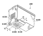
図1は、本実施形態におけるインクジェット記録装置の概略の構成を示す模式図である。インクジェット記録装置は、第1の記録ヘッドH1000、第2の記録ヘッドH1001を主走査方向に往復移動させる動作と、記録媒体108の所定ピッチごとに副走査方向に搬送させる動作とを繰り返している。これらの動きと同期させながら第1の記録ヘッドH1000、第2の記録ヘッドH1001から選択的にインクを吐出させ、記録媒体108に付着させることで、文字や記号、画像等を形成している。
(First embodiment)
FIG. 1 is a schematic diagram illustrating a schematic configuration of an ink jet recording apparatus according to the present embodiment. The ink jet recording apparatus repeats the operation of moving the first recording head H1000 and the second recording head H1001 back and forth in the main scanning direction and the operation of transporting the
第1の記録ヘッドH1000および第2の記録ヘッドH1001は、キャリッジ102に着脱可能に搭載されている。キャリッジ102は、ガイドシャフト103に摺動自在に支持され、不図示のモータ等の駆動手段によりガイドシャフト103に沿って往復移動する。記録媒体108は、搬送ローラ109により第1の記録ヘッドH1000および第2の記録ヘッドH1001のインク吐出面に対面する。そして、インク吐出面との距離を一定に維持するように、キャリッジ102の移動方向と交差する副走査方向に搬送される。
The first recording head H1000 and the second recording head H1001 are detachably mounted on the
本実施形態の記録ヘッドは、インクタンクと一体型のものであり、第1の記録ヘッドH1000にはブラックインクが充填され、第2の記録ヘッドH1001には複数のカラーインクが充填されている。 The recording head of this embodiment is an integral type with an ink tank. The first recording head H1000 is filled with black ink, and the second recording head H1001 is filled with a plurality of color inks.
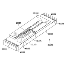
図2は、第1の記録ヘッドH1000を示す斜視図である。また、図3は、第1の記録ヘッドH1000を示す分解斜視図である。 FIG. 2 is a perspective view showing the first recording head H1000. FIG. 3 is an exploded perspective view showing the first recording head H1000.
第1の記録ヘッドは、シリコン製の基板を用いた記録素子基板H1100、電気配線テープH1300、支持部H1400およびインク容器H1500を有している。インク容器H1500は、内部にインクを保持し負圧を発生するためのインク吸収体を有することでインクタンクの機能を備える。インク容器H1500は、例えば、樹脂成形により形成されている。また、記録素子基板H1100にそのインクを導くためのインク流路を形成することでインク供給の機能を備えている。記録素子基板H1100の周囲は、記録素子基板周囲封止剤H1200により封止されている。電気配線テープH1300は、記録素子基板H1100に電力を供給し、信号を伝えるためのものである。 The first recording head includes a recording element substrate H1100 using a silicon substrate, an electric wiring tape H1300, a support portion H1400, and an ink container H1500. The ink container H1500 has an ink tank function by having an ink absorber for holding ink inside and generating negative pressure. The ink container H1500 is formed by resin molding, for example. Further, an ink supply function is provided by forming an ink flow path for guiding the ink to the recording element substrate H1100. The periphery of the recording element substrate H1100 is sealed with a recording element substrate surrounding sealant H1200. The electric wiring tape H1300 is for supplying power to the recording element substrate H1100 and transmitting signals.
支持部H1400は、記録素子基板H1100が接着剤により接合される部分であり、記録素子基板H1100が接合される第1の板状部H1530、空洞部H1600および空洞部を構成する空洞部壁H1700を有している。 The support portion H1400 is a portion to which the recording element substrate H1100 is bonded by an adhesive, and includes a first plate-shaped portion H1530 to which the recording element substrate H1100 is bonded, a cavity portion H1600, and a cavity portion wall H1700 constituting the cavity portion. Have.
支持部H1400は樹脂部材により形成されており、インク収納部H1500と一体に射出成形で製造されている。 The support portion H1400 is formed of a resin member, and is manufactured by injection molding integrally with the ink storage portion H1500.
図4は第1の記録素子基板H1100を示す破断斜視図である。Si基板H1110は、インク流路である貫通口のインク供給口H1102が形成されている。本実施形態のSi基板では、インク供給口H1102はウェット式の異方性エッチングにより形成され、四角錐台の形状を有している。インク供給口H1102を挟んだ両側には、インクを吐出するために利用されるエネルギー発生素子としての電気熱変換素子H1103がそれぞれ1列ずつ並んで配置されている。インク供給口H1102から供給されたインクは、各電気熱変換素子H1103の発熱によって発生した気泡の圧力により、各電気熱変換素子H1103に対向する吐出口H1107から吐出される。 FIG. 4 is a cutaway perspective view showing the first recording element substrate H1100. The Si substrate H1110 has an ink supply port H1102 as a through-hole that is an ink flow path. In the Si substrate of the present embodiment, the ink supply port H1102 is formed by wet-type anisotropic etching and has a quadrangular pyramid shape. On both sides of the ink supply port H1102, electrothermal conversion elements H1103 as energy generating elements used for ejecting ink are arranged in a line. The ink supplied from the ink supply port H1102 is discharged from the discharge port H1107 facing each electrothermal conversion element H1103 due to the pressure of the bubbles generated by the heat generated by each electrothermal conversion element H1103.
次に、本実施形態の第1の記録ヘッドH1000の落下による衝撃を吸収するための構造について説明する。 Next, a structure for absorbing an impact caused by the drop of the first recording head H1000 of this embodiment will be described.
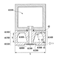
図5は、図2におけるV−V断面を示した断面図である。第1の記録ヘッドH1000は、インク収納部H1500、支持部H1400、記録素子基板H1100で構成されている。支持部H1400の内部には、インク収納部H1500から記録素子基板H1100までインクを供給するインク流路H1800となる空間が形成されている。支持部H1400は、第1板状部H1530と、第2板状部(以下、樹脂部とも称する)H1900と、インク流路H1800を挟むように設けられた2つの空洞部H1600を構成する壁部材(以下、空洞部壁とも称する)H1700とを有している。第2板状部は、第1板状部に関して吐出口H1107からインクが吐出される向きとは反対側に第1板状部からは離れて設けられている。壁部材H1700は第1板状部と第2板状部とをつなぐ板状の部材である。第1板状部は記録ヘッドの底面を構成し、壁部材は記録ヘッドの側面を構成している。 5 is a cross-sectional view showing a VV cross section in FIG. The first recording head H1000 includes an ink storage portion H1500, a support portion H1400, and a recording element substrate H1100. A space serving as an ink flow path H1800 for supplying ink from the ink storage portion H1500 to the recording element substrate H1100 is formed inside the support portion H1400. The support portion H1400 is a wall member that constitutes a first plate-like portion H1530, a second plate-like portion (hereinafter also referred to as a resin portion) H1900, and two hollow portions H1600 provided so as to sandwich the ink flow path H1800. (Hereinafter also referred to as a cavity wall) H1700. The second plate-like portion is provided away from the first plate-like portion on the side opposite to the direction in which ink is ejected from the ejection port H1107 with respect to the first plate-like portion. The wall member H1700 is a plate-like member that connects the first plate-like portion and the second plate-like portion. The first plate portion constitutes the bottom surface of the recording head, and the wall member constitutes the side surface of the recording head.
空洞部壁H1700は、樹脂部H1900に近づくに従い、厚みが増しており、断面形状は曲線状に増加している。すなわち、空洞部壁H1700は、樹脂部H1900につながる部位が曲面になっている。そして、空洞部壁H1700の第1板状部H1530につながる部位の厚みd1に対して、樹脂部H1900につながる部位の厚みd2が大きくなっている。 As the cavity wall H1700 approaches the resin part H1900, the thickness increases and the cross-sectional shape increases in a curved line. That is, the cavity part wall H1700 has a curved surface at the part connected to the resin part H1900. And the thickness d2 of the site | part connected to the resin part H1900 is large with respect to the thickness d1 of the site | part connected to the 1st plate-shaped part H1530 of the cavity part wall H1700.
このように支持部H1400に空洞部H1600を形成することにより、支持部H1400のうち、高度な位置決め精度が求められる記録素子基板H1100が接合される第1板状部H1530は、高い寸法精度と平面性が保たれる。 By forming the hollow portion H1600 in the support portion H1400 as described above, the first plate-like portion H1530 to which the recording element substrate H1100 that requires high positioning accuracy is bonded is provided with a high dimensional accuracy and a flat surface. Sex is maintained.
図6(a)および(b)は、従来の記録ヘッドに衝撃が与えられた場合について、記録素子基板が設けられた側から見た模式図である。高所からの落下等により、記録ヘッドH1000が衝撃を受けた場合、図6(a)に示す従来の記録ヘッドは、図6(b)に示すように変形する。従来の記録ヘッドでは、図6(b)に示すような記録素子基板H1100が接合された接合面の変形により、記録素子基板周囲封止剤H1200や接着剤を介して、記録素子基板は変形し、クラックが発生することがある。従来の構造では、記録素子基板H1100が接合された接合面の変形は、空洞部により空洞部壁が衝撃によってインク流路側に倒れるように変形することから、その変形量が大きくなる傾向にある。 FIGS. 6A and 6B are schematic views as seen from the side where the recording element substrate is provided when an impact is applied to a conventional recording head. When the recording head H1000 receives an impact due to dropping from a high place or the like, the conventional recording head shown in FIG. 6A is deformed as shown in FIG. 6B. In the conventional recording head, the recording element substrate is deformed via the recording element substrate surrounding sealant H1200 and the adhesive due to the deformation of the bonding surface to which the recording element substrate H1100 is bonded as shown in FIG. Cracks may occur. In the conventional structure, the deformation of the joint surface to which the recording element substrate H1100 is bonded is deformed so that the cavity portion wall is tilted to the ink flow path side due to the impact, and the amount of deformation tends to increase.
しかしながら、本実施形態の支持部H1400では、空洞部壁H1700の壁の樹脂部につながる部位の厚みd2を、第1板状部につながる部位の厚みd1よりも厚くしている。すなわち、衝撃を受けた場合に力点となる空洞部壁H1700の第1板状部につながる部位の厚みよりも、変形の支点となる樹脂部につながる部位の厚みの方が大きい構成となっている。このような構成とすることで、空洞部壁の樹脂部H1900につながる部位を支点とし、第1板状部H1530につながる部位を力点とする変形に対する空洞部壁H1700の剛性を上げることができる。これにより、第1板状部H1530の変形を軽減することにより、記録素子基板H1100の変形を低減することができる。 However, in the support part H1400 of this embodiment, the thickness d2 of the part connected to the resin part of the wall of the cavity part wall H1700 is made thicker than the thickness d1 of the part connected to the first plate-like part. That is, the thickness of the portion connected to the resin portion serving as a fulcrum of deformation is greater than the thickness of the portion connected to the first plate-shaped portion of the hollow portion wall H1700 serving as a power point when receiving an impact. . With such a configuration, it is possible to increase the rigidity of the cavity wall H1700 with respect to deformation using the part connected to the resin part H1900 of the cavity part wall as a fulcrum and the part connected to the first plate-like part H1530 as a power point. Accordingly, the deformation of the recording element substrate H1100 can be reduced by reducing the deformation of the first plate-like portion H1530.
また、空洞部壁H1700の厚みの変化を、図5に示すように曲線状にするとで、空洞部H1600を広く確保することができる。また、曲線状にすることで衝撃による応力集中を避け、前述した空洞部壁H1700の変形に対する剛性をさらに上げることができる。 Further, if the change in the thickness of the cavity wall H1700 is curved as shown in FIG. 5, a wide cavity H1600 can be secured. Further, by making the shape curved, it is possible to avoid stress concentration due to impact and further increase the rigidity against deformation of the cavity wall H1700 described above.
さらに、図5に示すように、変形の支点となる樹脂部につながる部位の厚さを、記録ヘッドの内側に向かって増加させることで、記録ヘッドの幅が増加することを抑制しつつ、前述した空洞部壁H1700の変形に対する剛性を上げることができる。 Further, as shown in FIG. 5, the thickness of the portion connected to the resin portion serving as a fulcrum of deformation is increased toward the inner side of the recording head, thereby suppressing the increase in the width of the recording head. The rigidity against the deformation of the hollow wall H1700 can be increased.
また、射出成形による成形する場合に、金型に樹脂が流れやすくするためにd1は最小でも0.4mmの大きさが必要である。d2は最大で図5に示す樹脂部H1900の幅Lの半分の大きさまで設定することができる。好ましくはd2を幅Lの3分の1程度までの大きさとすることで、樹脂部H1900の成形性を良好に保つことができる。 Further, in the case of molding by injection molding, in order to facilitate the flow of the resin into the mold, d1 needs to be at least 0.4 mm. d2 can be set up to half the width L of the resin portion H1900 shown in FIG. Preferably, by setting d2 to a size up to about one third of the width L, the moldability of the resin portion H1900 can be kept good.
図5に示すように、空洞部壁H1700は第1板状部H1530とつながる部位と樹脂部H1900とつながる部位とに曲率を有する。空洞部壁H1700の断面形状について、第1板状部H1530とつながる部位の曲線の曲率半径r1は、クラックが発生しにくいように0.3mm以上とすることが望ましい。本実施形態では、r1=1.0mmとした。樹脂部H1900とつながる部位の曲線の曲率半径r2は、最大で図5に示す壁部材H1700の高さhからr1を引いた大きさとすることができる。好ましくはr2を樹脂部H1900の幅Lの3分の1程度までの大きさとすることで、樹脂部H1900の成形性を良好に保つことができる。本実施形態ではr2=2.5mmとした。 As shown in FIG. 5, the cavity wall H1700 has a curvature at a part connected to the first plate-like part H1530 and a part connected to the resin part H1900. Regarding the cross-sectional shape of the cavity wall H1700, it is desirable that the curvature radius r1 of the curve connected to the first plate-like part H1530 be 0.3 mm or more so that cracks are unlikely to occur. In this embodiment, r1 = 1.0 mm. The radius of curvature r2 of the curve connected to the resin portion H1900 can be set to a size obtained by subtracting r1 from the height h of the wall member H1700 shown in FIG. Preferably, the moldability of the resin portion H1900 can be kept good by setting r2 to a size up to about one third of the width L of the resin portion H1900. In this embodiment, r2 = 2.5 mm.
なお、本実施形態では、空洞部壁H1700の第1板状部につながる部位の厚みd1は、ある程度薄い方が好ましい。空洞部壁H1700と記録素子基板H1100との接合面の間にある、第1板状部H1530の一部が、衝撃を吸収する部位である衝撃吸収部H2000として機能しているためである。壁の厚みd1を壁の厚みd2と同等に大きくしてしまうと、壁の厚みd1の増加分だけ衝撃吸収部H2000の距離が短くなってしまうことによる。 In the present embodiment, it is preferable that the thickness d1 of the portion connected to the first plate-like portion of the cavity wall H1700 is thin to some extent. This is because a part of the first plate-shaped portion H1530 between the cavity portion wall H1700 and the recording element substrate H1100 functions as an impact absorbing portion H2000 that is a portion that absorbs the impact. If the wall thickness d1 is increased to be equal to the wall thickness d2, the distance of the shock absorbing portion H2000 is shortened by the increase in the wall thickness d1.
つまり、本実施形態の支持部H1400は、空洞部壁H1700の樹脂部につながる部位の厚みd2を、第1板状部につなげる部位の厚みd1よりも厚くすることにより、流路H1800側への倒れこみ方向の剛性上げ、空洞部壁H1700の倒れこみによる第1板状部H1530の変形を低減する。さらに、空洞部壁H1700の厚みd1を落下の衝撃によって割れが発生しない程度に薄くして、第1板状部H1530の衝撃吸収部H2000の幅をできるだけ多くとることにより、さらに記録素子基板H1100の接合面の変形を低減している。 That is, the support portion H1400 of the present embodiment is configured such that the thickness d2 of the portion connected to the resin portion of the cavity portion wall H1700 is larger than the thickness d1 of the portion connected to the first plate-like portion, thereby moving toward the flow path H1800 side. The rigidity in the collapse direction is increased, and deformation of the first plate-shaped portion H1530 due to the collapse of the cavity wall H1700 is reduced. Further, by reducing the thickness d1 of the cavity wall H1700 to such an extent that cracks do not occur due to a drop impact, and by making the width of the impact absorbing portion H2000 of the first plate-like portion H1530 as large as possible, the recording element substrate H1100 is further increased. The deformation of the joint surface is reduced.
以上により、空洞部H1600を広く確保することにより、第1板状部H1530の平面性を保つとともに、記録ヘッドH1000の落下等による記録ヘッドH1000の吐出不良による画像劣化を防止することができる。さらに、記録素子基板H1100に複数のインクを供給する場合、別部材を空洞部内に挿入して新たなインク流路を設ける場合の自由度を持たせることもできる。 As described above, by ensuring the wide hollow portion H1600, it is possible to maintain the flatness of the first plate-like portion H1530 and to prevent image deterioration due to defective ejection of the recording head H1000 due to dropping of the recording head H1000 or the like. Further, when supplying a plurality of inks to the recording element substrate H1100, it is possible to provide a degree of freedom when a new ink flow path is provided by inserting another member into the cavity.
なお、本実施形態は、インク収納部と記録ヘッドが一体型である記録ヘッドについて説明をしているが、本発明は、インク収納部が交換可能な記録ヘッドであってもよい。 Although the present embodiment describes a recording head in which the ink storage portion and the recording head are integrated, the present invention may be a recording head in which the ink storage portion is replaceable.
(第1実施形態の変形例)
第1実施形態の記録ヘッドH1000の支持部H1400は、さらに空洞部H1600に、記録素子接合面を補強する梁H2005および溝H2004を備えていてもよい。
(Modification of the first embodiment)
The support portion H1400 of the recording head H1000 of the first embodiment may further include a beam H2005 and a groove H2004 that reinforce the recording element joint surface in the hollow portion H1600.
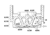
図7は、本実施形態の変形例の、図2におけるVII−VII断面を示した断面図である。本実施形態の支持部H1400は、インク流路H1800を囲む空洞部H1600に、2つの梁H2005を備えている。また、第1板状部の空洞部壁H1700と記録素子基板H1100の接合面の間に、より衝撃を吸収する構造である衝撃吸収溝H2004を備えている。このような梁H2005および衝撃吸収溝H2004を備えることにより、衝撃に対して、より変形を低減させることができる。 FIG. 7 is a cross-sectional view showing a VII-VII cross section in FIG. 2 according to a modification of the present embodiment. The support part H1400 of the present embodiment includes two beams H2005 in a cavity part H1600 that surrounds the ink flow path H1800. Further, an impact absorbing groove H2004 having a structure for absorbing more impact is provided between the cavity wall H1700 of the first plate-like portion and the bonding surface of the recording element substrate H1100. By providing such a beam H2005 and the impact absorbing groove H2004, deformation can be further reduced with respect to the impact.
(第2実施形態)
第1実施形態の記録ヘッドH1000の支持部H1400の形状は、曲線状に空洞壁が変化するものであったが、本発明はこのような形状に限定されるものではない。
(Second Embodiment)
The shape of the support portion H1400 of the recording head H1000 of the first embodiment is such that the cavity wall changes in a curved shape, but the present invention is not limited to such a shape.
図8は本実施形態の記録ヘッドH1000の断面を示した断面図である。本実施形態の支持部H1400の空洞壁H1700は、第1実施形態と同様に、樹脂部H1900に近づくに従い、厚みが増している。空洞部壁H1700の厚みの変化は、直線状になっている。すなわち、第1実施形態の支持部H1400の空洞部壁H1700の厚みの変化は、曲線状であったが、本実施形態の空洞部壁H1700の厚みは、空洞部壁の任意の点p2から点p1では、樹脂部に向かって単調増加している。 FIG. 8 is a sectional view showing a section of the recording head H1000 of the present embodiment. Similar to the first embodiment, the thickness of the hollow wall H1700 of the support portion H1400 of the present embodiment increases as it approaches the resin portion H1900. The change in the thickness of the cavity wall H1700 is linear. That is, the change in the thickness of the cavity portion wall H1700 of the support portion H1400 of the first embodiment is curved, but the thickness of the cavity portion wall H1700 of this embodiment is changed from an arbitrary point p2 of the cavity portion wall. In p1, it is increasing monotonously toward the resin part.
本実施形態のように、空洞部壁H1700を直線状に増加・減少させた場合、空洞部壁H1700を曲線状に増加・減少させるよりも空洞部壁H1700を厚くしやすいため、より剛性を高くしやすい。ただし、射出成形によって製造される樹脂部材のため、空洞部壁H1700が厚くなり過ぎてしまうと、支持部H1400の寸法精度や平面性が維持できる範囲にすることが好ましい。 When the cavity wall H1700 is linearly increased / decreased as in the present embodiment, the cavity wall H1700 is more easily thickened than when the cavity wall H1700 is increased / decreased in a curved line. It's easy to do. However, since the resin member is manufactured by injection molding, when the cavity wall H1700 becomes too thick, it is preferable that the dimensional accuracy and flatness of the support H1400 be maintained.
(第2実施形態の変形例)
第2実施形態の記録ヘッドH1000の支持部H1400は、さらに空洞部壁H1700に空洞を備えていてもよい。
(Modification of the second embodiment)
The support H1400 of the recording head H1000 of the second embodiment may further include a cavity in the cavity wall H1700.
図9は、本実施形態の変形例の記録ヘッドH1000の断面を示した断面図である。本実施形態の変形例の記録ヘッドH1000は、空洞部壁H1700の樹脂部H1900につながる部位に空洞H1601が設けられている。本変形例では、空洞部壁内の任意の点p6から点p5では樹脂部H1900に向かって単調増加している。また、空洞部壁H1700の厚みは、厚みd3<厚みd4の関係になっている。このように、空洞部壁H1700の樹脂部H1900につながる部位に空洞H1601を設けることにより、樹脂硬化時に均一に冷却することができ、寸法精度や平面性を維持することができる。また、空洞部壁H1700の第1板状部H1530につながる部位に、樹脂硬化時に均一に冷却して寸法精度や平面性を維持するために空洞H1602を形成しても良い。 FIG. 9 is a cross-sectional view showing a cross section of a recording head H1000 according to a modification of the present embodiment. In a recording head H1000 according to a modification of the present embodiment, a cavity H1601 is provided at a portion connected to the resin part H1900 of the cavity wall H1700. In this modification, the point increases monotonously from the arbitrary point p6 to the point p5 in the cavity wall toward the resin part H1900. The thickness of the cavity wall H1700 has a relationship of thickness d3 <thickness d4. As described above, by providing the cavity H1601 at the part connected to the resin part H1900 of the cavity part wall H1700, it is possible to cool uniformly when the resin is cured, and it is possible to maintain dimensional accuracy and flatness. In addition, a cavity H1602 may be formed in a part connected to the first plate-like part H1530 of the cavity part wall H1700 in order to cool uniformly during resin curing and maintain dimensional accuracy and flatness.
なお、本実施形態の変形例では、空洞H1601の断面は三角形でるが、本発明の空洞の断面はこのような形に限定されるものではない。すなわち、空洞H1601は、空洞部壁H1700の剛性を大きくする効果を有する構造と、射出成形の寸法精度に重要な、樹脂硬化時の冷却に効果のある位置・形状・サイズを満たしていれば、どのような形状であってもよい。 In the modification of this embodiment, the cross section of the cavity H1601 is a triangle, but the cross section of the cavity of the present invention is not limited to such a shape. That is, the cavity H1601 satisfies the structure, which has the effect of increasing the rigidity of the cavity wall H1700, and the position, shape, and size that are important for the dimensional accuracy of the injection molding and effective for cooling during resin curing. Any shape is acceptable.
また、本変形例の空洞部壁H1700は、樹脂部H1900に向かうにつれて、すなわち点p6から点5に向かって厚さが単調増加するものである。しかしながら、本変形例は、第1実施形態のような、空洞部壁H1700の厚さが曲線状に変化するものであっても適用可能である。 In addition, the cavity wall H1700 of the present modification monotonically increases in thickness as it goes toward the resin part H1900, that is, from the point p6 to the point 5. However, the present modification is applicable even when the thickness of the cavity wall H1700 changes in a curved shape as in the first embodiment.
H1000 記録ヘッド
H1100 記録素子基板
H1400 支持部
H1500 インク収納部
H1530 第1の板状部
H1600 空洞部
H1700 空洞部壁
H1800 インク流路
H1900 樹脂部
H1000 Recording head H1100 Recording element substrate H1400 Support section H1500 Ink storage section H1530 First plate-shaped section H1600 Cavity section H1700 Cavity section wall H1800 Ink flow path H1900 Resin section
Claims (8)
前記壁部材は前記第2板状部につながる部位の厚さが前記第1板状部につながる部位の厚さより大きいことを特徴とする記録ヘッド。 An element substrate provided with an energy generating element that generates energy used for discharging ink, a first plate-like portion provided with the element substrate, and discharging the ink with respect to the first plate-like portion A recording comprising: a second plate-like portion provided away from the first plate-like portion on the opposite side of the direction; and a plate-like wall member connecting the first plate-like portion and the second plate-like portion. Head,
The recording head according to claim 1, wherein a thickness of a portion of the wall member connected to the second plate-shaped portion is larger than a thickness of a portion connected to the first plate-shaped portion.
Priority Applications (2)
| Application Number | Priority Date | Filing Date | Title |
|---|---|---|---|
| JP2009125607A JP5541656B2 (en) | 2008-06-17 | 2009-05-25 | Recording head |
| US12/483,457 US8246146B2 (en) | 2008-06-17 | 2009-06-12 | Printing head |
Applications Claiming Priority (3)
| Application Number | Priority Date | Filing Date | Title |
|---|---|---|---|
| JP2008157901 | 2008-06-17 | ||
| JP2008157901 | 2008-06-17 | ||
| JP2009125607A JP5541656B2 (en) | 2008-06-17 | 2009-05-25 | Recording head |
Publications (2)
| Publication Number | Publication Date |
|---|---|
| JP2010023489A true JP2010023489A (en) | 2010-02-04 |
| JP5541656B2 JP5541656B2 (en) | 2014-07-09 |
Family
ID=41414346
Family Applications (1)
| Application Number | Title | Priority Date | Filing Date |
|---|---|---|---|
| JP2009125607A Active JP5541656B2 (en) | 2008-06-17 | 2009-05-25 | Recording head |
Country Status (2)
| Country | Link |
|---|---|
| US (1) | US8246146B2 (en) |
| JP (1) | JP5541656B2 (en) |
Cited By (1)
| Publication number | Priority date | Publication date | Assignee | Title |
|---|---|---|---|---|
| CN107031189A (en) * | 2016-01-08 | 2017-08-11 | 佳能株式会社 | Fluid ejection head, liquid discharge apparatus and manufacture method |
Families Citing this family (5)
| Publication number | Priority date | Publication date | Assignee | Title |
|---|---|---|---|---|
| JP5340038B2 (en) * | 2008-06-17 | 2013-11-13 | キヤノン株式会社 | Ink jet recording head and liquid jet recording head |
| JP5541655B2 (en) * | 2008-06-17 | 2014-07-09 | キヤノン株式会社 | Recording head |
| JP6137918B2 (en) | 2013-04-12 | 2017-05-31 | キヤノン株式会社 | Inkjet recording head and inkjet recording apparatus |
| JP6562694B2 (en) | 2014-05-30 | 2019-08-21 | キヤノン株式会社 | Liquid discharge head, liquid discharge apparatus, and method for electrically connecting liquid discharge head and liquid storage container |
| JP6494352B2 (en) | 2014-05-30 | 2019-04-03 | キヤノン株式会社 | Liquid discharge head |
Citations (5)
| Publication number | Priority date | Publication date | Assignee | Title |
|---|---|---|---|---|
| JPH03161342A (en) * | 1989-11-21 | 1991-07-11 | Seiko Epson Corp | Ink jet head |
| JP2002248746A (en) * | 2001-02-23 | 2002-09-03 | Canon Inc | Recorder, recording head and carriage |
| JP2005254749A (en) * | 2004-03-15 | 2005-09-22 | Ricoh Co Ltd | Liquid-droplet discharge head and manufacturing method for same, liquid cartridge, liquid-droplet discharge device and ink-jet recording device |
| JP2006102979A (en) * | 2004-09-30 | 2006-04-20 | Fuji Photo Film Co Ltd | Liquid discharge head |
| JP2006231530A (en) * | 2005-02-22 | 2006-09-07 | Brother Ind Ltd | Liquid transfer device |
Family Cites Families (12)
| Publication number | Priority date | Publication date | Assignee | Title |
|---|---|---|---|---|
| SG52140A1 (en) | 1994-03-04 | 1998-09-28 | Canon Kk | Ink jet recording head and method of manufacture therefor and laser processing apparatus and ink jet recording apparatus |
| EP0847866B1 (en) | 1994-11-02 | 2003-01-08 | Seiko Epson Corporation | Ink supply tank for an ink jet type recording unit |
| JP3821498B2 (en) | 1995-01-23 | 2006-09-13 | セイコーエプソン株式会社 | Inkjet recording unit and ink cartridge |
| AUPQ605800A0 (en) * | 2000-03-06 | 2000-03-30 | Silverbrook Research Pty Ltd | Printehead assembly |
| JP2002001959A (en) | 2000-04-17 | 2002-01-08 | Canon Inc | Liquid jet head, cartridge, picture forming device, and manufacturing method for liquid jet head |
| US6631966B2 (en) | 2000-11-13 | 2003-10-14 | Canon Kabushiki Kaisha | Recording head and recording apparatus with temperature control |
| TW577823B (en) | 2003-04-09 | 2004-03-01 | Benq Corp | Ink-jet cartridge |
| JP4743851B2 (en) | 2005-07-08 | 2011-08-10 | キヤノン株式会社 | Recording head manufacturing method |
| US7984967B2 (en) | 2007-04-13 | 2011-07-26 | Canon Kabushiki Kaisha | Ink jet head |
| JP2009090572A (en) | 2007-10-10 | 2009-04-30 | Canon Inc | Ink-jet recording head and recording device |
| JP5541655B2 (en) | 2008-06-17 | 2014-07-09 | キヤノン株式会社 | Recording head |
| JP5340038B2 (en) | 2008-06-17 | 2013-11-13 | キヤノン株式会社 | Ink jet recording head and liquid jet recording head |
-
2009
- 2009-05-25 JP JP2009125607A patent/JP5541656B2/en active Active
- 2009-06-12 US US12/483,457 patent/US8246146B2/en active Active
Patent Citations (5)
| Publication number | Priority date | Publication date | Assignee | Title |
|---|---|---|---|---|
| JPH03161342A (en) * | 1989-11-21 | 1991-07-11 | Seiko Epson Corp | Ink jet head |
| JP2002248746A (en) * | 2001-02-23 | 2002-09-03 | Canon Inc | Recorder, recording head and carriage |
| JP2005254749A (en) * | 2004-03-15 | 2005-09-22 | Ricoh Co Ltd | Liquid-droplet discharge head and manufacturing method for same, liquid cartridge, liquid-droplet discharge device and ink-jet recording device |
| JP2006102979A (en) * | 2004-09-30 | 2006-04-20 | Fuji Photo Film Co Ltd | Liquid discharge head |
| JP2006231530A (en) * | 2005-02-22 | 2006-09-07 | Brother Ind Ltd | Liquid transfer device |
Cited By (1)
| Publication number | Priority date | Publication date | Assignee | Title |
|---|---|---|---|---|
| CN107031189A (en) * | 2016-01-08 | 2017-08-11 | 佳能株式会社 | Fluid ejection head, liquid discharge apparatus and manufacture method |
Also Published As
| Publication number | Publication date |
|---|---|
| US8246146B2 (en) | 2012-08-21 |
| JP5541656B2 (en) | 2014-07-09 |
| US20090309926A1 (en) | 2009-12-17 |
Similar Documents
| Publication | Publication Date | Title |
|---|---|---|
| JP5541656B2 (en) | Recording head | |
| JP4743851B2 (en) | Recording head manufacturing method | |
| US8128199B2 (en) | Ink jet print head, method for manufacturing ink jet print head, and printing apparatus | |
| JP5002232B2 (en) | Inkjet recording device | |
| JP2007283501A (en) | Inkjet recording head | |
| JP4724484B2 (en) | Recording head and ink jet recording apparatus | |
| KR20110047129A (en) | Method for manufacturing liquid jet head, liquid jet device and liquid jet head | |
| JP2011073245A (en) | Liquid ejecting head and liquid ejecting apparatus | |
| JP2009090572A (en) | Ink-jet recording head and recording device | |
| JP5164639B2 (en) | Liquid discharge head and recording apparatus using the same | |
| JP5541655B2 (en) | Recording head | |
| JP4672840B2 (en) | Liquid discharge head | |
| JP4823038B2 (en) | Ink jet head cartridge, recording head, ink storage container, and method of manufacturing ink jet head cartridge | |
| JP2007185835A (en) | Inkjet head, ink tank cartridge, and inkjet printer | |
| JP2005144919A (en) | Inkjet recording head | |
| JP5672249B2 (en) | Inkjet head | |
| JP2007276385A (en) | Ink jet recording head and ink jet recorder | |
| JPH0531908A (en) | Liquid injection device with plurality of discharge parts, and recording device using the same | |
| JP2007230085A (en) | Recording head and recording device | |
| JP5595161B2 (en) | Liquid ejection head, liquid ejection device | |
| JP2009006560A (en) | Ink-jet recording head and recording device | |
| JP2009132095A (en) | Liquid discharge head and liquid discharge device | |
| JP5949891B2 (en) | Inkjet head | |
| JP2007015280A (en) | Liquid delivering head and liquid injecting method for liquid delivering head | |
| JP2007313667A (en) | Liquid jet recording head |
Legal Events
| Date | Code | Title | Description |
|---|---|---|---|
| RD02 | Notification of acceptance of power of attorney |
Free format text: JAPANESE INTERMEDIATE CODE: A7422 Effective date: 20101106 |
|
| A621 | Written request for application examination |
Free format text: JAPANESE INTERMEDIATE CODE: A621 Effective date: 20120521 |
|
| A977 | Report on retrieval |
Free format text: JAPANESE INTERMEDIATE CODE: A971007 Effective date: 20130426 |
|
| A131 | Notification of reasons for refusal |
Free format text: JAPANESE INTERMEDIATE CODE: A131 Effective date: 20130514 |
|
| A521 | Written amendment |
Free format text: JAPANESE INTERMEDIATE CODE: A523 Effective date: 20130708 |
|
| TRDD | Decision of grant or rejection written | ||
| A01 | Written decision to grant a patent or to grant a registration (utility model) |
Free format text: JAPANESE INTERMEDIATE CODE: A01 Effective date: 20140408 |
|
| A61 | First payment of annual fees (during grant procedure) |
Free format text: JAPANESE INTERMEDIATE CODE: A61 Effective date: 20140430 |
|
| R151 | Written notification of patent or utility model registration |
Ref document number: 5541656 Country of ref document: JP Free format text: JAPANESE INTERMEDIATE CODE: R151 |