JP2010022156A - Core for rotor - Google Patents
Core for rotor Download PDFInfo
- Publication number
- JP2010022156A JP2010022156A JP2008181563A JP2008181563A JP2010022156A JP 2010022156 A JP2010022156 A JP 2010022156A JP 2008181563 A JP2008181563 A JP 2008181563A JP 2008181563 A JP2008181563 A JP 2008181563A JP 2010022156 A JP2010022156 A JP 2010022156A
- Authority
- JP
- Japan
- Prior art keywords
- magnet
- magnet holding
- protrusion
- rotor core
- rotation axis
- Prior art date
- Legal status (The legal status is an assumption and is not a legal conclusion. Google has not performed a legal analysis and makes no representation as to the accuracy of the status listed.)
- Granted
Links
Images


Abstract
Description
本発明は、モータの回転子に採用される回転子用コア(以下、「ロータコア」とも称する)に関し、特に磁石埋込型モータに搭載される回転子用コアに関する。 The present invention relates to a rotor core (hereinafter also referred to as “rotor core”) employed in a rotor of a motor, and more particularly to a rotor core mounted on a magnet-embedded motor.
モータにおいて、磁石をロータコアの内部に埋込んだIPMモータ(Interior Permanent Magnet Motor;磁石埋込型モータ)が実用化されている。IPMモータについては、下掲の特許文献1〜4に開示されている。 As a motor, an IPM motor (Interior Permanent Magnet Motor) in which a magnet is embedded in a rotor core has been put into practical use. The IPM motor is disclosed in the following Patent Documents 1 to 4.
図10及び図11は従来の回転子用コア91,95の一部を示す平面図であり、図10は一の磁石埋設孔92が2つの磁石保持部922,924を有している態様を、図11は一の磁石埋設孔96が3つの磁石保持部962,964,966を有している態様を、それぞれ示している。
10 and 11 are plan views showing a part of
これらの磁石保持部922,924のそれぞれに磁石942,944を埋設すると、磁石埋設孔92の内部で磁石942と磁石944とが衝突するおそれがある。また磁石保持部962,964,966のそれぞれに磁石982,984,986を埋設すると、磁石埋設孔96の内部で磁石982と磁石984、あるいは磁石982と磁石986とが衝突するおそれがある。
If the
このような衝突によって磁石942,944,982,984,986の角部が破損する等の不具合を招来する。当該不具合を回避又は抑制するために、磁石942,944,982,984,986の移動を抑制することが肝要である。
Such a collision causes problems such as breakage of the corners of the
図12は図11の態様に磁石保持突起963,965,967,969を設けた回転子用コア95Aの一部を示す平面図である。図12に示す如く、例えば磁石保持突起963,965が第1の磁石保持部962に埋設される磁石982と、第2の磁石保持部964に埋設される磁石984との衝突を抑制する。また、磁石保持突起967,969が磁石982と、第3の磁石保持部966に埋設される磁石986との衝突を抑制する。
12 is a plan view showing a part of a
しかしながら、第1の磁石保持突起963と第2の磁石保持突起965との間、また、第3の磁石保持突起967と第4の磁石保持突起969との間には、それぞれ鋭角で小さな凹部が形成されているため、金型で打抜いて成型するには不向きな形状であった。
However, between the first magnet holding projection 963 and the second
そこで、本発明は上記課題に鑑み、磁石の移動を回避又は抑制してかつ、金型で成型容易な構造を呈する回転子用コアを提供することを目的とする。 SUMMARY OF THE INVENTION In view of the above problems, an object of the present invention is to provide a rotor core that avoids or suppresses movement of a magnet and exhibits a structure that can be easily molded with a mold.
上記課題を解決すべく、第1の発明は、シャフト(12)の回転軸(Q)に沿った方向に延在する柱状部(14,14F)と、前記柱状部の前記回転軸と反対側の側面(140)よりも前記回転軸側で、前記方向に延在する複数の磁石保持部(162,164,166,164F,166F)を有する磁石埋設孔(16,16F)の複数とを備える回転子用コア(10,10F)であって、前記磁石埋設孔は、前記側面側に配置される一対の端部(22,24)を有し、前記端部の各々から相互に近付きつつ前記端部よりも前記回転軸側へと延在して各々の前記端部に対応する第1及び第2の前記磁石保持部を呈し、第1の前記磁石保持部と第2の前記磁石保持部との間に屈曲部(32,42)を呈し、前記屈曲部は、前記磁石埋設孔の内部に向かって突出する突部(30,40,40A,40B,40C,40D,40E,40F)を呈する。 In order to solve the above-mentioned problem, the first invention is a columnar portion (14, 14F) extending in a direction along the rotation axis (Q) of the shaft (12), and the opposite side of the columnar portion to the rotation axis. A plurality of magnet embedding holes (16, 16F) having a plurality of magnet holding portions (162, 164, 166, 164F, 166F) extending in the direction on the rotating shaft side of the side surface (140) of The rotor core (10, 10F), wherein the magnet embedding hole has a pair of end portions (22, 24) disposed on the side surface side, and approaches each other from the end portions. The first and second magnet holding portions and the second magnet holding portions that extend from the end portion toward the rotating shaft side and exhibit the first and second magnet holding portions corresponding to the end portions, respectively. Bend portions (32, 42) between the magnet embedded holes and the bend portions. Toward projection projecting exhibits (30,40,40A, 40B, 40C, 40D, 40E, 40F) and.
第2の発明は、第1の発明であって、前記突部(30,40,40A,40B,40F)は、前記磁石埋設孔を規定する面のうち、前記回転軸(Q)側の第1面(152,154,156,154F,156F)から、前記第1面と対向する第2面(172,174,176)へと向けて突出する。 2nd invention is 1st invention, Comprising: The said protrusion (30, 40, 40A, 40B, 40F) is the 1st by the side of the said rotating shaft (Q) among the surfaces which prescribe | regulate the said magnet embedding hole. Projecting from one surface (152, 154, 156, 154F, 156F) toward a second surface (172, 174, 176) facing the first surface.
第3の発明は、第2の発明であって、前記回転軸(Q)方向を法線とする面内における前記突部(40A)の突端部(44A;62A,66A)は、前記突部と対向する第2面(172,176)と平行を呈する。 3rd invention is 2nd invention, Comprising: The protrusion part (44A; 62A, 66A) of the said protrusion (40A) in the surface which makes the said rotating shaft (Q) direction a normal line is the said protrusion. And parallel to the second surface (172, 176) facing each other.
第4の発明は、第2の発明であって、前記回転軸(Q)方向を法線とする面内における前記突部(40B)の突端部(44B)は、前記突部と対向する第2面(172,176)が呈する外周側屈曲部(42)を中心とする凹弧を呈する。 4th invention is 2nd invention, Comprising: The protrusion part (44B) of the said protrusion (40B) in the surface which makes the said rotating shaft (Q) direction a normal line opposes the said protrusion. It presents a concave arc centered on the outer periphery side bent portion (42) exhibited by the two surfaces (172, 176).
第5の発明は、第1の発明であって、前記突部(40C,40D,40E)は、前記磁石埋設孔を規定する面のうち、前記回転軸(Q)側の第1面(152,154,156)へと向けて、前記第1面と対向する第2面(172,174,176)から突出する。 5th invention is 1st invention, Comprising: The said protrusion (40C, 40D, 40E) is the 1st surface (152) of the said rotating shaft (Q) side among the surfaces which prescribe | regulate the said magnet embedding hole. , 154, 156) projecting from the second surface (172, 174, 176) facing the first surface.
第6の発明は、第5の発明であって、前記回転軸(Q)方向を法線とする面内における前記突部(40D)の突端部(44D)は、前記突部と対向する第1面(152,156)と平行を呈する。 6th invention is 5th invention, Comprising: The protrusion part (44D) of the said protrusion (40D) in the surface which makes the said rotating shaft (Q) direction a normal line opposes the said protrusion. It is parallel to one surface (152, 156).
第7の発明は、第5の発明であって、前記回転軸(Q)方向を法線とする面内における前記突部(40E)の突端部(44E)は、前記突部と対向する第1面(152,156)が呈する内周側屈曲部(48)と略平行な凸弧を呈する。 7th invention is 5th invention, Comprising: The protrusion part (44E) of the said protrusion (40E) in the surface which makes the said rotating shaft (Q) direction a normal line opposes the said protrusion. A convex arc substantially parallel to the inner peripheral bent portion (48) exhibited by one surface (152, 156) is exhibited.
第1の発明によれば、隣接する磁石保持部に配設される磁石が接触することを回避でき、磁石の破損を回避又は抑制できる。また、柱状部から磁石埋設孔を打抜くのが容易である。すなわち、一体成型が容易である。 According to 1st invention, it can avoid that the magnet arrange | positioned by the adjacent magnet holding | maintenance part contacts, and can avoid or suppress breakage | damage of a magnet. Moreover, it is easy to punch out the magnet embedding hole from the columnar part. That is, integral molding is easy.
第2の発明によれば、突部の基底部の強度を確保しやすい。 According to the second invention, it is easy to ensure the strength of the base of the protrusion.
第3の発明によれば、突端部と第2面との間の空隙の幅を一定値以上確保できるので、磁気抵抗の低下を回避又は抑制し、漏洩磁束を低減できる。 According to the third invention, since the width of the gap between the protruding end portion and the second surface can be secured at a certain value or more, the decrease in magnetic resistance can be avoided or suppressed, and the leakage magnetic flux can be reduced.
第4の発明によれば、漏洩磁束を低減してかつ、磁石埋設孔を打抜くための金型の寿命を向上できる。 According to the fourth invention, it is possible to reduce the leakage magnetic flux and improve the life of the mold for punching out the magnet embedding hole.
第5の発明によれば、突端部中心付近の空隙を他の領域付近の空隙に比べて狭くするので、磁気抵抗の低下を回避又は抑制し、漏洩磁束を低減できる。 According to the fifth aspect, since the gap near the center of the tip is made narrower than the gap near the other area, it is possible to avoid or suppress the decrease in magnetic resistance and reduce the leakage magnetic flux.
第6の発明によれば、突端部と第1面との間の空隙の幅を一定値以上確保できるので、磁気抵抗の低下を回避又は抑制し、漏洩磁束を低減できる。 According to the sixth invention, since the width of the gap between the protruding end portion and the first surface can be secured at a certain value or more, the decrease in magnetic resistance can be avoided or suppressed, and the leakage magnetic flux can be reduced.
第7の発明によれば、漏洩磁束を低減してかつ、磁石埋設孔を打抜くための金型の寿命を向上できる。 According to the seventh invention, it is possible to reduce the leakage magnetic flux and improve the life of the mold for punching out the magnet embedding hole.
以下、本発明の好適な実施形態について、図面を参照しながら説明する。なお、図1を初めとする以下の図面には、本発明に関係する要素のみを示す。 Preferred embodiments of the present invention will be described below with reference to the drawings. In the following drawings including FIG. 1, only elements related to the present invention are shown.
〈構成の概略〉
図1は回転子用コア10の概略を例示する斜視図である。回転子用コア10は、磁石埋設孔16を呈する柱状部14を備えている。
<Outline of configuration>
FIG. 1 is a perspective view illustrating an outline of a
柱状部14は例えば、略円柱状に形成され、当該円柱体の上面の中心と下面の中心とを結ぶ高さ方向に沿って当該方向から見た平面視で略円形の貫通孔11を呈しており、貫通孔11にシャフト12が締まりばめされる。そしてシャフト12が回転軸Qを中心に回転する。
The
柱状部14の側面のうち回転軸Q側で貫通孔11を規定する側面110と、側面110とは反対側の側面140との間の領域では、回転軸Q方向に延在する複数の磁石埋設孔16を呈している。
A plurality of magnets extending in the direction of the rotation axis Q are embedded in a region between the
一の磁石埋設孔16は例えば、回転軸Q方向を法線とする面内で略U字型を呈している。具体的には磁石埋設孔16は、貫通孔11に隣接して貫通孔11を規定する円の接線方向に延在する第1の磁石保持部162と、第1の磁石保持部162の両端でそれぞれ屈曲部25,27を呈して回転軸Qから遠離る方向に延在する第2の磁石保持部164及び第3の磁石保持部166とを有している。第1の磁石保持部162と第2の磁石保持部164とが成す角(すなわち、屈曲部25が成す角)、及び第1の磁石保持部162と第3の磁石保持部166とが成す角(すなわち、屈曲部27が成す角)は、ともに180度未満(ただし鈍角)を呈している。つまり、第2の磁石保持部164の側面140側の端部22と、第3の磁石保持部166の側面140側の端部24とを結ぶ線分Lが、第1の磁石保持部162よりも側面140側に位置する。
One
換言すれば、磁石埋設孔16のそれぞれは側面140側に配置される一対の端部22,24を有しており、両端部22,24のそれぞれから相互に近付きつつ両端部22,24よりも回転軸Q側へと延在している。磁石埋設孔16が最もシャフト12に近接する第1の磁石保持部162は、一対の端部22,24同士の回転軸Qについての周方向の位置の間にある。
In other words, each of the
付言すれば、一の磁石埋設孔16は、一対の端部22,24の回転軸Qについての周方向における位置の間において側面140側に鈍角を呈する一対の屈曲部25,27を有する。そして、一対の屈曲部25,27で挟まれる第1の磁石保持部162は、第1の磁石保持部162が配置された位置における回転軸Qについての径方向に対して略直角に平坦となる。
In other words, one
このような概略構成を呈する回転子用コア10が、以下の各実施形態で示す形状を呈することにより、磁石埋設孔16の内部で磁石が破損することを回避又は抑制できる。
The
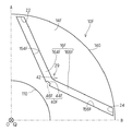
〈第1実施形態〉
図2は本発明の第1実施形態に係る回転子用コア10の一部の平面図であり、図1のAOBで分離した領域を回転軸Q方向に沿って俯瞰した状態を示している。また、図3は図2のうちの一部の領域Pの拡大図である。
<First Embodiment>
FIG. 2 is a plan view of a part of the
第1実施形態では、屈曲部25に相当する位置に突部30を設けている。具体的には、屈曲部25を規定する部位のうち、回転軸Qから遠い側を外周側屈曲部32とすると、外周側屈曲部32と対向する位置、すなわち屈曲部25を規定する部位のうち回転軸Qに近い側の位置において、外周側屈曲部32へと向けて突出する突部30を呈する。同様に、屈曲部27に相当する位置に突部40を設けている。具体的には、屈曲部27を規定する部位のうち、回転軸Qから遠い側を外周側屈曲部42とすると、外周側屈曲部42と対向する位置、すなわち屈曲部27を規定する部位のうち回転軸Qに近い側の位置において、外周側屈曲部42へと向けて突出する突部40を呈する。要するに、突部30,40は回転子用コア10の径方向内側から径方向外側へと向けて突出する。
In the first embodiment, the
突部30は、第1の磁石保持部162を規定する面のうち回転軸Q側の第1面152と、第2の磁石保持部164を規定する面のうち回転軸Q側の第1面154との間に形成される。突部30は、第1の磁石保持部162の第1面152の端部において、回転軸Q方向を法線とする面内で第1面152と略垂直を呈し、第2の磁石保持部164の第1面154の端部(端部22とは反対側の端部)において、同面内で第1面154と略垂直を呈する。これによって、第1の磁石保持部162で保持される磁石(図示省略)と、第2の磁石保持部164で保持される磁石(図示省略)との衝突を回避し、しかも磁石が突部30と衝突して破損することを回避又は抑制できる。
The
突部40も同様に、第1の磁石保持部162を規定する面のうち回転軸Q側の第1面152と、第3の磁石保持部166を規定する面のうち回転軸Q側の第1面156との間に形成される。突部40は、第1の磁石保持部162の第1面152の端部において、回転軸Q方向を法線とする面内で第1面152と略垂直を呈し、第3の磁石保持部166の第1面156の端部(端部24とは反対側の端部)において、同面内で第1面156と略垂直を呈する。これによって、第1の磁石保持部162で保持される磁石(図示省略)と、第3の磁石保持部166で保持される磁石(図示省略)との衝突を回避し、しかも磁石が突部40と衝突して破損することを回避又は抑制できる。
Similarly, the
ここで図3に示す如く、突部40の突端部44は略平坦を呈する。回転軸Q方向を法線とする面内において、第1の磁石保持部162の延在方向と第3の磁石保持部166の延在方向とは非平行である(鈍角を成している)から、突部40が第1の磁石保持部162の第1面152に垂直でかつ第3の磁石保持部166の第1面に垂直にすると、突部40は当該面内で外周側屈曲部42へと向けて幅狭となる。突端部44は当該幅狭となっている部位を予め定められた位置で略平坦を呈する。
Here, as shown in FIG. 3, the projecting
今、第1の磁石保持部162側の突部40の下端及び、第3の磁石保持部166側の突部40の下端を結んだ直線を突部40の基底部46とすると、突部40は当該面内において突端部44及び基底部46を平行な辺とする台形を呈する。なお、図面では一点鎖線で示している。このような簡単な形状を呈することにより、金型を用いて磁石埋設孔16を打抜くのが容易になり、しかも突部40を一体成型できる。また、突端部44よりも基底部46の方が当該面内での長さが長いので、突部40の強度を確保しやすい。これらのことは突部30についても同様である。
Now, assuming that a straight line connecting the lower end of the
〈第2実施形態〉
上記第1実施形態では突端部44が略平坦を呈している態様について説明したが、本発明はこれに限定されるものではない。ここでは、本発明の第2実施形態として突端部の形状が異なる態様について説明する。なお、以下の実施形態において上記第1実施形態と同様の機能を有する要素については同一符号を付してその説明を省略する。
Second Embodiment
Although the said 1st Embodiment demonstrated the aspect in which the
図4は本発明の第2実施形態に係る回転子用コア10の一部の領域Pの拡大図であり、図2中の領域Pに本発明の第2実施形態を適用した場合の拡大図である。
FIG. 4 is an enlarged view of a partial region P of the
図4に示す如く第1の磁石保持部162と第3の磁石保持部166との間の領域で径方向内側から径方向外側へと向けて突出する突部40Aは以下のような構造を呈している。すなわち、上記第1実施形態で示した突端部44に相当する突端部44Aが、回転軸Q方向を法線とする面内において、突端部44Aと対向する面と略平行を呈している。
As shown in FIG. 4, the
具体的には突端部44Aは、外周側屈曲部42と対応する位置を境界として、第1の磁石保持部162を規定する面のうち第1面152と対向する第2面172と略平行を呈する部位62Aと、第3の磁石保持部166を規定する面のうち第1面156と対向する第2面176と略平行を呈する部位66Aとを有している。要するに、突端部44Aと外周側屈曲部42とが略平行を呈していると把握できる。
Specifically, the projecting
このような構造を呈することによって、外周側屈曲部42と突端部44Aとの間の空隙の幅を一定値以上確保できるので、磁気抵抗の低下を招来せず、漏洩磁束を低減できる。
By exhibiting such a structure, the gap width between the outer peripheral side
〈第3実施形態〉
上記第2実施形態は、図12で説明した態様と同様に、突端部44Aに鋭角を呈する箇所が存在する。そのため、金型で磁石埋設孔16を打抜く場合には負担を掛ける場合がある。ここでは、本発明の第3実施形態として突端部の形状が更に異なる態様について説明する。
<Third Embodiment>
In the second embodiment, as in the aspect described with reference to FIG. Therefore, when punching out the
図5は本発明の第3実施形態に係る回転子用コア10の一部の領域Pの拡大図であり、図2中の領域Pに本発明の第3実施形態を適用した場合の拡大図である。
FIG. 5 is an enlarged view of a partial region P of the
図5に示す如く第1の磁石保持部162と第3の磁石保持部166との間の領域で径方向内側から径方向外側へ突出する突部40Bは以下のような構造を呈している。すなわち、上記第1実施形態で示した突端部44に相当する突端部44Bが、回転軸Q方向を法線とする面内において、外周側屈曲部42を中心とする凹弧を呈している。
As shown in FIG. 5, the protrusion 40B protruding from the radially inner side to the radially outer side in the region between the first
望ましくは、当該凹弧の半径は、突端部44Bの辺縁から第2面172,176までの最短距離よりも長いことが望ましい。これにより、外周側屈曲部42と突端部44Bとの間の空隙の幅を一定値以上確保できるので、磁気抵抗の低下を招来せず、漏洩磁束を低減できる。しかも突部40Bは鋭角を呈する部位がないので、金型で打抜いて成型するのが容易である。
Desirably, the radius of the concave arc is longer than the shortest distance from the edge of the projecting end portion 44B to the
〈第4実施形態〉
上記第1ないし第3実施形態では、突部40,40A,40Bが径方向内側から径方向外側へ突出する態様について説明したが、本発明はこれに限定されるものではない。ここでは、本発明の第4実施形態として突部が径方向外側から径方向内側へと突出する態様について説明する。
<Fourth embodiment>
In the first to third embodiments, the
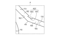
図6は本発明の第4実施形態に係る回転子用コア10の一部の領域Pの拡大図であり、図2中の領域Pに本発明の第4実施形態を適用した場合の拡大図である。
FIG. 6 is an enlarged view of a partial region P of the
図6に示す如く突部40Cは第1の磁石保持部162と第3の磁石保持部166との間の領域において、径方向外側から径方向内側、具体的には内周側屈曲部48へと向けて突出する。
As shown in FIG. 6, the
突部40Cは、第1の磁石保持部162を規定する面のうち回転軸Qとは反対側の第2面172と、第3の磁石保持部166を規定する面のうち回転軸Qとは反対側の第2面176との間に形成される。突部40Cは、第1の磁石保持部162の第2面172の端部において、回転軸Q方向を法線とする面内で第2面172と略垂直を呈し、第3の磁石保持部166の第2面176の端部(端部24とは反対側の端部)において、同面内で第2面176と略垂直を呈する。これによって、第1の磁石保持部162で保持される磁石(図示省略)と、第3の磁石保持部166で保持される磁石(図示省略)との衝突を回避し、しかも磁石が突部40Cと衝突して破損することを回避又は抑制できる。
The
突部40Cを径方向外側に設けることによって、径方向内側に設ける場合に比べて次のような利点を有する。すなわち、突部40Cとこれに対向する第1面152,156との間の空隙の幅を一定値以上確保するには、突部40Cの突端部44Cが略平坦を呈する場合、突端部44Cの辺縁から第1面152,156までの最短距離のみを考慮すれば、突端部44Cの中央部は必然的に当該最短距離よりも長くなるので、突端部44Cの設計の自由度が高まる。
By providing the
ただし、回転軸Q方向を法線とする面内において、第1の磁石保持部162の延在方向と第3の磁石保持部166の延在方向との成す角度が小さくなると、突部40Cの基底部46Dの長さが短くなるので、径方向内側に突部40,40A,40Bを設けるか又は径方向外側に突部40Cを設けるかは適宜に選択することが必要である。
However, if the angle formed by the extending direction of the first
〈第5実施形態〉
上記第4実施形態で示したように突端部44Cが略平坦を呈している場合、突部40Cは第2面172,176のそれぞれに対して略垂直を呈しているので、突端部44Cの辺縁は鋭角を呈することになり、金型の長寿命化を阻害するおそれがある。ここでは、本発明の第5実施形態として突端部の形状を上記第4実施形態とは異ならせる態様について説明する。
<Fifth Embodiment>
As shown in the fourth embodiment, when the
図7は本発明の第5実施形態に係る回転子用コア10の一部の領域Pの拡大図であり、図2中の領域Pに本発明の第5実施形態を適用した場合の拡大図である。
FIG. 7 is an enlarged view of a partial region P of the
図7に示す如く突部40Dは第1の磁石保持部162と第3の磁石保持部166との間の領域で径方向外側から内周側屈曲部48へと向けて突出する突部40Dは以下のような構造を呈している。すなわち、上記第4実施形態で示した突端部44Cに相当する突端部44Dが、回転軸Q方向を法線とする面内において、突端部44Dと対向する面と略平行を呈している。なお、本実施形態の場合には、必ずしも対向する面と平行である必要はなく、鋭角を呈する部位が低減されれば良い。
As shown in FIG. 7, the
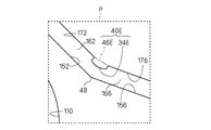
〈第6実施形態〉
図8は本発明の第6実施形態に係る回転子用コア10の一部の領域Pの拡大図であり、図2中の領域Pに本発明の第6実施形態を適用した場合の拡大図である。
<Sixth Embodiment>
FIG. 8 is an enlarged view of a partial region P of the
図8に示す如く、突部40Eは第1の磁石保持部162と第3の磁石保持部166との間の領域で径方向外側から内周側屈曲部48へと向けて突出する突部40Eは以下のような構造を呈している。すなわち、上記第4実施形態で示した突端部44Cに相当する突端部44Eが、回転軸Q方向を法線とする面内において、内周側屈曲部48に接する円弧と略平行な凸弧を呈している。
As shown in FIG. 8, the
このように凸弧を呈することによって金型の寿命を向上できる。 Thus, the lifetime of a metal mold | die can be improved by exhibiting a convex arc.
〈変形例〉
以上、本発明の好適な態様について説明したが、本発明はこれに限定されるものではない。
<Modification>
As mentioned above, although the suitable aspect of this invention was demonstrated, this invention is not limited to this.
図9は本発明の変形例に係る回転子用コア10Fの一部の平面図である。なお、図9の態様の全体図については省略するが、図1のAOBで分離した領域を回転軸Q方向に沿って俯瞰した状態を示している。
FIG. 9 is a plan view of a part of a
本発明の変形例では図9に示す如く、磁石埋設孔16(図1参照)が第2の磁石保持部164F及び第3の磁石保持部166Fの2つを有し、1つの屈曲部29を呈している。そして、屈曲部29に相当する位置に突部40Fを設けている。具体的には、屈曲部29を規定する部位のうち、外周側屈曲部42へと向けて突出する突部40Fを呈する。
In the modified example of the present invention, as shown in FIG. 9, the magnet embedding hole 16 (see FIG. 1) has two of the second
突部40Fは、第2の磁石保持部164Fを規定する面のうち回転軸Q側の第1面154Fと、第3の磁石保持部166Fを規定する面のうち回転軸Q側の第1面156Fとの間に形成される。突部40Fは、第2磁石保持部164Fの第1面154Fの端部(端部22とは反対側の端部)において、回転軸Q方向を法線とする面内で第1面154Fと略垂直を呈し、第3磁石保持部166Fの第1面の端部(端部24とは反対側の端部)において、同面内で第1面156Fとの間と略垂直を呈する。これによって、第2の磁石保持部164Fで保持される磁石(図示省略)と、第3の磁石保持部166Fで保持される磁石(図示省略)との衝突を回避し、しかも磁石が突部40Fと衝突して破損することを回避又は抑制できる。
The
ここでは、突部40Fの突端部44Fが略平坦を呈し、突部40Fの基底部46Fを考慮すると、突部40Fが台形を呈する態様を示しているが、上述の各実施形態を適用しても構わない。
Here, the
ここでは、突部40Fの突端部44Fが略平坦を呈し、突部40Fの基底部46Fを考慮すると、突部40Fが台形を呈する態様を示しているが、上述の実施形態を適宜組合せても良い。
Here, the
10,10F 回転子用コア
12 シャフト
14,14F 柱状部
140 側面
152,154,156,154F,156F 第1面
16,16F 磁石埋設孔
162,164,166,164F,166F 磁石保持部
172,174,176 第2面
22,24 端部
25,27,29 屈曲部
30,40,40A,40B,40C,40D,40E,40F 突部
32,42 外周側屈曲部
48 内周側屈曲部
44,44A,44B,44C,44D,44E,44F 突端部
46,46A,46B,46C,46D,46E,46F 基底部
10, 10F
Claims (7)
前記柱状部の前記回転軸と反対側の側面(140)よりも前記回転軸側で、前記方向に延在する複数の磁石保持部(162,164,166,164F,166F)を有する磁石埋設孔(16,16F)の複数と
を備える回転子用コア(10,10F)であって、
前記磁石埋設孔は、
前記側面側に配置される一対の端部(22,24)を有し、
前記端部の各々から相互に近付きつつ前記端部よりも前記回転軸側へと延在して各々の前記端部に対応する第1及び第2の前記磁石保持部を呈し、
第1の前記磁石保持部と第2の前記磁石保持部との間に屈曲部(32,42)を呈し、
前記屈曲部は、前記磁石埋設孔の内部に向かって突出する突部(30,40,40A,40B,40C,40D,40E,40F)を呈する、回転子用コア。 Columnar portions (14, 14F) extending in a direction along the rotation axis (Q) of the shaft (12);
A magnet embedding hole having a plurality of magnet holding portions (162, 164, 166, 164F, 166F) extending in the direction on the rotating shaft side with respect to the side surface (140) opposite to the rotating shaft of the columnar portion. A rotor core (10, 10F) comprising a plurality of (16, 16F),
The magnet embedding hole is
A pair of end portions (22, 24) disposed on the side surface;
The first and second magnet holding portions corresponding to each of the end portions extending from the end portion toward the rotating shaft side while approaching each other from each of the end portions,
Bends (32, 42) between the first magnet holding part and the second magnet holding part;
The said bending part is a core for rotors which exhibits the protrusion (30, 40, 40A, 40B, 40C, 40D, 40E, 40F) which protrudes toward the inside of the said magnet embedding hole.
前記突部(30,40,40A,40B,40F)は、前記磁石埋設孔を規定する面のうち、前記回転軸(Q)側の第1面(152,154,156,154F,156F)から、前記第1面と対向する第2面(172,174,176)へと向けて突出する、回転子用コア。 The rotor core (10, 10F) according to claim 1,
The protrusions (30, 40, 40A, 40B, 40F) extend from the first surface (152, 154, 156, 154F, 156F) on the rotating shaft (Q) side of the surface defining the magnet embedding hole. A rotor core that protrudes toward a second surface (172, 174, 176) opposite to the first surface.
前記回転軸(Q)方向を法線とする面内における前記突部(40A)の突端部(44A;62A,66A)は、前記突部と対向する第2面(172,176)と平行を呈する、回転子用コア。 A rotor core (10) according to claim 2,
The projecting end (44A; 62A, 66A) of the projecting part (40A) in a plane normal to the direction of the rotation axis (Q) is parallel to the second surface (172, 176) facing the projecting part. Presented core for rotors.
前記回転軸(Q)方向を法線とする面内における前記突部(40B)の突端部(44B)は、前記突部と対向する第2面(172,176)が呈する外周側屈曲部(42)を中心とする凹弧を呈する、回転子用コア。 A rotor core (10) according to claim 2,
The projecting end (44B) of the projecting part (40B) in a plane having the normal to the rotation axis (Q) direction is an outer peripheral side bent part (172, 176) facing the projecting part ( 42) A rotor core having a concave arc centered at 42).
前記突部(40C,40D,40E)は、前記磁石埋設孔を規定する面のうち、前記回転軸(Q)側の第1面(152,154,156)へと向けて、前記第1面と対向する第2面(172,174,176)から突出する、回転子用コア。 A rotor core (10) according to claim 1,
The protrusions (40C, 40D, 40E) are formed on the first surface toward the first surface (152, 154, 156) on the rotating shaft (Q) side of the surface defining the magnet embedding hole. And a rotor core that protrudes from the second surface (172, 174, 176) opposite to.
前記回転軸(Q)方向を法線とする面内における前記突部(40D)の突端部(44D)は、前記突部と対向する第1面(152,156)と平行を呈する、回転子用コア。 A rotor core (10) according to claim 5,
The protrusion (44D) of the protrusion (40D) in a plane normal to the direction of the rotation axis (Q) is parallel to the first surface (152, 156) facing the protrusion. For core.
前記回転軸(Q)方向を法線とする面内における前記突部(40E)の突端部(44E)は、前記突部と対向する第1面(152,156)が呈する内周側屈曲部(48)と略平行な凸弧を呈する、回転子用コア。 A rotor core (10) according to claim 5,
The projecting end (44E) of the projecting part (40E) in a plane having the normal direction to the rotation axis (Q) is an inner circumferential bent part exhibited by the first surface (152, 156) facing the projecting part. A rotor core that exhibits a convex arc substantially parallel to (48).
Priority Applications (1)
| Application Number | Priority Date | Filing Date | Title |
|---|---|---|---|
| JP2008181563A JP5077114B2 (en) | 2008-07-11 | 2008-07-11 | Rotor core |
Applications Claiming Priority (1)
| Application Number | Priority Date | Filing Date | Title |
|---|---|---|---|
| JP2008181563A JP5077114B2 (en) | 2008-07-11 | 2008-07-11 | Rotor core |
Publications (2)
| Publication Number | Publication Date |
|---|---|
| JP2010022156A true JP2010022156A (en) | 2010-01-28 |
| JP5077114B2 JP5077114B2 (en) | 2012-11-21 |
Family
ID=41706502
Family Applications (1)
| Application Number | Title | Priority Date | Filing Date |
|---|---|---|---|
| JP2008181563A Expired - Fee Related JP5077114B2 (en) | 2008-07-11 | 2008-07-11 | Rotor core |
Country Status (1)
| Country | Link |
|---|---|
| JP (1) | JP5077114B2 (en) |
Cited By (4)
| Publication number | Priority date | Publication date | Assignee | Title |
|---|---|---|---|---|
| JP2014107913A (en) * | 2012-11-26 | 2014-06-09 | Honda Motor Co Ltd | Rotor for rotary electric machine |
| JP5609976B2 (en) * | 2010-07-28 | 2014-10-22 | 日産自動車株式会社 | Rotor for rotating electrical machines |
| JP2016105696A (en) * | 2016-03-07 | 2016-06-09 | 日立アプライアンス株式会社 | Permanent magnet synchronous machine |
| JP2017158282A (en) * | 2016-03-01 | 2017-09-07 | 本田技研工業株式会社 | Rotary electric machine |
Citations (2)
| Publication number | Priority date | Publication date | Assignee | Title |
|---|---|---|---|---|
| JP2006296045A (en) * | 2005-04-07 | 2006-10-26 | Asmo Co Ltd | Embedded magnet type motor and its manufacturing method |
| JP2007159196A (en) * | 2005-12-01 | 2007-06-21 | Aichi Elec Co | Permanent magnet rotating machine and compressor |
-
2008
- 2008-07-11 JP JP2008181563A patent/JP5077114B2/en not_active Expired - Fee Related
Patent Citations (2)
| Publication number | Priority date | Publication date | Assignee | Title |
|---|---|---|---|---|
| JP2006296045A (en) * | 2005-04-07 | 2006-10-26 | Asmo Co Ltd | Embedded magnet type motor and its manufacturing method |
| JP2007159196A (en) * | 2005-12-01 | 2007-06-21 | Aichi Elec Co | Permanent magnet rotating machine and compressor |
Cited By (5)
| Publication number | Priority date | Publication date | Assignee | Title |
|---|---|---|---|---|
| JP5609976B2 (en) * | 2010-07-28 | 2014-10-22 | 日産自動車株式会社 | Rotor for rotating electrical machines |
| US9024499B2 (en) | 2010-07-28 | 2015-05-05 | Nissan Motor Co., Ltd. | Rotating electric machine rotor |
| JP2014107913A (en) * | 2012-11-26 | 2014-06-09 | Honda Motor Co Ltd | Rotor for rotary electric machine |
| JP2017158282A (en) * | 2016-03-01 | 2017-09-07 | 本田技研工業株式会社 | Rotary electric machine |
| JP2016105696A (en) * | 2016-03-07 | 2016-06-09 | 日立アプライアンス株式会社 | Permanent magnet synchronous machine |
Also Published As
| Publication number | Publication date |
|---|---|
| JP5077114B2 (en) | 2012-11-21 |
Similar Documents
| Publication | Publication Date | Title |
|---|---|---|
| JP5057171B2 (en) | Embedded magnet type motor | |
| JP2005033941A (en) | Stator core for permanent magnet motor, and permanent magnet motor | |
| JP6343127B2 (en) | motor | |
| JP5042178B2 (en) | Electric motor stator and electric motor and compressor | |
| JP6098614B2 (en) | Manufacturing method of rotor | |
| JP2006311772A (en) | Dynamo-electric motor | |
| JP5256778B2 (en) | Motor rotor and motor | |
| JP2016093021A (en) | Rotor structure | |
| JP5077114B2 (en) | Rotor core | |
| JP2010004663A (en) | Permanent magnet synchronous motor | |
| JP2007028734A (en) | Dynamo-electric machine | |
| TWI487246B (en) | Reluctance motor | |
| JP4457612B2 (en) | Compressor, electric motor and its stator | |
| JP6707726B1 (en) | Rotor, motor using the rotor, and electronic device | |
| JP2010252554A (en) | Rotor and motor | |
| JP2004320989A (en) | Permanent magnet embedding motor | |
| KR20150030040A (en) | Stator core and motor including stator core | |
| JP2011172359A (en) | Split rotor and electric motor | |
| JP2020088879A (en) | Rotor, and rotary electric machine provided with the same | |
| JP2023000580A (en) | Base member, spindle motor, and hard disk driving device | |
| JP2009247111A (en) | Limited angle motor | |
| JP2010063209A (en) | Core for rotor | |
| JP6424171B2 (en) | Tolerance ring and hard disk drive | |
| JP2008022592A (en) | Electric motor | |
| JP2009296859A (en) | Armature |
Legal Events
| Date | Code | Title | Description |
|---|---|---|---|
| A977 | Report on retrieval |
Free format text: JAPANESE INTERMEDIATE CODE: A971007 Effective date: 20111005 |
|
| A131 | Notification of reasons for refusal |
Free format text: JAPANESE INTERMEDIATE CODE: A131 Effective date: 20111011 |
|
| A521 | Written amendment |
Free format text: JAPANESE INTERMEDIATE CODE: A523 Effective date: 20111130 |
|
| TRDD | Decision of grant or rejection written | ||
| A01 | Written decision to grant a patent or to grant a registration (utility model) |
Free format text: JAPANESE INTERMEDIATE CODE: A01 Effective date: 20120731 |
|
| A01 | Written decision to grant a patent or to grant a registration (utility model) |
Free format text: JAPANESE INTERMEDIATE CODE: A01 |
|
| A61 | First payment of annual fees (during grant procedure) |
Free format text: JAPANESE INTERMEDIATE CODE: A61 Effective date: 20120813 |
|
| FPAY | Renewal fee payment (event date is renewal date of database) |
Free format text: PAYMENT UNTIL: 20150907 Year of fee payment: 3 |
|
| FPAY | Renewal fee payment (event date is renewal date of database) |
Free format text: PAYMENT UNTIL: 20150907 Year of fee payment: 3 |
|
| LAPS | Cancellation because of no payment of annual fees |