JP2009247111A - Limited angle motor - Google Patents
Limited angle motor Download PDFInfo
- Publication number
- JP2009247111A JP2009247111A JP2008090626A JP2008090626A JP2009247111A JP 2009247111 A JP2009247111 A JP 2009247111A JP 2008090626 A JP2008090626 A JP 2008090626A JP 2008090626 A JP2008090626 A JP 2008090626A JP 2009247111 A JP2009247111 A JP 2009247111A
- Authority
- JP
- Japan
- Prior art keywords
- coil
- magnetic pole
- base
- stator
- angle motor
- Prior art date
- Legal status (The legal status is an assumption and is not a legal conclusion. Google has not performed a legal analysis and makes no representation as to the accuracy of the status listed.)
- Pending
Links
Images


Abstract
Description
本発明は、有限角モータに関し、特に、固定子基部に第1及び第2磁極を設けることで、コイルを鎖交する有効磁束を高めることができ、単位体積あたりの力密度を大きくできるようにするための新規な改良に関するものである。 The present invention relates to a finite angle motor, and in particular, by providing the first and second magnetic poles at the stator base, the effective magnetic flux interlinking the coils can be increased, and the force density per unit volume can be increased. The present invention relates to a new improvement.
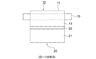
従来用いられていたこの種の有限角モータとしては、例えば特許文献1等に示されている有限角モータが用いられている。図4は、従来の有限角モータを示す断面図である。
図において、有限角モータは、固定子10と可動子20とにより構成されている。前記固定子10は、固定子基部11とコイル15から構成されている。前記固定子基部11の内面側には1/4円筒形状曲面11cが形成されており、この1/4円筒形状曲面11cには予め環状に成形された前記コイル15が貼り付けられている。
前記可動子20は、可動子基部21と永久磁石22とにより構成されている。前記可動子基部21は駆動軸24を中心に回動可能に設けられており、永久磁石22は前記可動子基部21の先端に取り付けられている。
前記コイル15に通電されると、前記コイル15と前記永久磁石22との間に反発力が発生する。すなわち、前記コイル15に流される電流の向きに応じて、前記駆動軸24を中心に前記可動子基部21が所定の有限角で時計方向又は反時計方向に駆動される。
As this type of finite-angle motor conventionally used, for example, a finite-angle motor shown in Patent Document 1 or the like is used. FIG. 4 is a cross-sectional view showing a conventional finite angle motor.
In the figure, the finite angle motor is composed of a
The
When the
上記のような従来の有限角モータでは、コイル15が固定子基部11の内面(1/4円筒形状曲面11c)に貼り付けられただけのコアレス構造とされているので、コイル15を鎖交する有効磁束が低く、単位体積あたりの力密度が小さくなっている。
In the conventional finite angle motor as described above, the
本発明は、上記のような課題を解決するためになされたものであり、その目的は、コイルを鎖交する有効磁束を高めることができ、単位体積あたりの力密度を大きくできる有限角モータを提供することである。 The present invention has been made in order to solve the above-described problems, and an object of the present invention is to provide a finite angle motor that can increase the effective magnetic flux interlinking coils and increase the force density per unit volume. Is to provide.
本発明に係る有限角モータは、固定子基部の基部端面の中央から内方へ突出された第1磁極と、前記基部端面から突出されるとともに前記第1磁極の両側に配置された一対の第2磁極と、前記第1磁極と前記各第2磁極との間のスロットに配設されたコイルと、前記第1磁極及び前記各第2磁極の第1及び第2先端部の端面に形成された円弧状の固定子側曲面と、前記固定子側曲面に対向し、駆動軸を中心に回動可能な可動子基部と、前記可動子基部の内面に設けられた永久磁石とを備え、前記コイルと前記永久磁石との間に発生する反発力によって、前記可動子基部が前記駆動軸を中心に所定の有限角で駆動される構成である。 A finite angle motor according to the present invention includes a first magnetic pole projecting inward from the center of the base end face of the stator base, and a pair of first magnetic poles protruding from the base end face and disposed on both sides of the first magnetic pole. Two magnetic poles, a coil disposed in a slot between the first magnetic pole and each second magnetic pole, and end faces of first and second tip portions of the first magnetic pole and each second magnetic pole. An arc-shaped stator-side curved surface, a mover base facing the stator-side curved surface and rotatable about a drive shaft, and a permanent magnet provided on an inner surface of the mover base, The movable element base is driven at a predetermined finite angle about the drive shaft by a repulsive force generated between a coil and the permanent magnet.
本発明の有限角モータによれば、コイルが第1磁極と第2磁極との間のスロットに配設されているので、コイルを鎖交する有効磁束を高めることができ、単位体積あたりの力密度を大きくできる。 According to the finite angle motor of the present invention, since the coil is disposed in the slot between the first magnetic pole and the second magnetic pole, the effective magnetic flux interlinking the coil can be increased, and the force per unit volume can be increased. The density can be increased.
以下、本発明を実施するための最良の形態について、図面を参照して説明する。
実施の形態1.
図1は本発明の実施の形態1による有限角モータを示す正面図であり、図2は図1の有限角モータを示す側面図であり、図3は図2の有限角モータを示す上面図である。なお、従来の有限角モータと同一又は同等部分については同一の符号を用いて説明する。
図において、有限角モータは、固定子10と可動子20とにより構成されている。前記固定子10には、板状の固定子基部11が設けられており、この固定子基部11の基部端面11aからは第1磁極12と一対の第2磁極13とが内方へ突出されている。前記第1磁極12は前記固定子基部11の幅方向Aに沿う中央に配置されており、前記各第2磁極13は前記第1磁極12の両側に配置されている。具体的には、前記各第2磁極13は、前記固定子基部11の両側の側端部11bに配設されている。前記第1磁極12と前記各第2磁極13との間にはスロットが設けられており、このスロットにはコイル15が配設されている。すなわち、図3に示すように、コイル15の中心孔15aに前記第1磁極12が挿通されており、コイル15の両側に前記各第2磁極13が接している。なお、この実施の形態では、前記コイル15は例えば自動巻線機等により前記第1磁極12に巻回されたものである。
The best mode for carrying out the present invention will be described below with reference to the drawings.
Embodiment 1 FIG.
1 is a front view showing a finite angle motor according to Embodiment 1 of the present invention, FIG. 2 is a side view showing the finite angle motor of FIG. 1, and FIG. 3 is a top view showing the finite angle motor of FIG. It is. The same or equivalent parts as those of the conventional finite angle motor will be described using the same reference numerals.
In the figure, the finite angle motor is composed of a
図1に戻り、前記第1磁極12及び前記各第2磁極13は第1及び第2先端部16,17を有している。前記第1先端部16には、この第1先端部16の両側面から前記各第2磁極13に向かって突出する第1縁部16aが設けられており、前記各第2先端部17には、各第2先端部17の内側面から前記第1磁極12に向かって突出する第2縁部17aがそれぞれ設けられている。第1及び第2先端部16,17の端面には、円弧状の固定子側曲面18が形成されている。なお、前記各第2先端部17の第2先端部17の外側面は平面状に形成されている。
Returning to FIG. 1, the first
前記可動子20は、前記固定子10に対向して配置されており、扇状の可動子基部21と永久磁石22とにより構成されている。前記可動子基部21は、前記固定子側曲面18に対向する円弧状の可動子側曲面23を有しており、駆動軸24を中心に回動可能に設けられている。前記永久磁石22は、可動子基部21の内面すなわち可動子側曲面23に貼り付けられており、具体的には、互いに異なる極が前記固定子側曲面18に対向するように配置された一対の磁石片により構成されている。
The
前記コイル15に通電されると、前記コイル15と前記永久磁石22との間に反発力が発生し、この反発力によって、前記可動子基部21が前記駆動軸24を中心に駆動される。すなわち、前記コイル15に流される電流の向きに応じて、前記可動子基部21が所定の有限角で時計方向又は反時計方向に駆動される。
When the
11 固定子基部
11a 基部端面
12,13 第1及び第2磁極
15 コイル
16,17 第1及び第2先端部
18 固定子側曲面
21 可動子基部
22 永久磁石
23 可動子側曲面
24 駆動軸
DESCRIPTION OF
Claims (1)
前記基部端面(11a)から突出されるとともに前記第1磁極(12)の両側に配置された一対の第2磁極(13)と、
前記第1磁極(12)と前記各第2磁極(13)との間のスロットに配設されたコイル(15)と、
前記第1磁極(12)及び前記各第2磁極(13)の第1及び第2先端部(16,17)の端面に形成された円弧状の固定子側曲面(18)と、
前記固定子側曲面(18)に対向し、駆動軸(24)を中心に回動可能な可動子基部(21)と、
前記可動子基部(21)の内面に設けられた永久磁石(22)と
を備え、
前記コイル(15)と前記永久磁石(22)との間に発生する反発力によって、前記可動子基部(21)が前記駆動軸(24)を中心に所定の有限角で駆動されることを特徴とする有限角モータ。 A first magnetic pole (12) protruding inward from the center of the base end face (11a) of the stator base (11);
A pair of second magnetic poles (13) protruding from the base end face (11a) and disposed on both sides of the first magnetic pole (12);
A coil (15) disposed in a slot between the first magnetic pole (12) and each second magnetic pole (13);
An arcuate stator-side curved surface (18) formed on end surfaces of the first and second tip portions (16, 17) of the first magnetic pole (12) and the second magnetic poles (13);
A mover base (21) facing the stator-side curved surface (18) and rotatable about a drive shaft (24);
A permanent magnet (22) provided on the inner surface of the mover base (21),
The movable element base (21) is driven at a predetermined finite angle about the drive shaft (24) by a repulsive force generated between the coil (15) and the permanent magnet (22). A finite angle motor.
Priority Applications (1)
| Application Number | Priority Date | Filing Date | Title |
|---|---|---|---|
| JP2008090626A JP2009247111A (en) | 2008-03-31 | 2008-03-31 | Limited angle motor |
Applications Claiming Priority (1)
| Application Number | Priority Date | Filing Date | Title |
|---|---|---|---|
| JP2008090626A JP2009247111A (en) | 2008-03-31 | 2008-03-31 | Limited angle motor |
Publications (1)
| Publication Number | Publication Date |
|---|---|
| JP2009247111A true JP2009247111A (en) | 2009-10-22 |
Family
ID=41308423
Family Applications (1)
| Application Number | Title | Priority Date | Filing Date |
|---|---|---|---|
| JP2008090626A Pending JP2009247111A (en) | 2008-03-31 | 2008-03-31 | Limited angle motor |
Country Status (1)
| Country | Link |
|---|---|
| JP (1) | JP2009247111A (en) |
Cited By (4)
| Publication number | Priority date | Publication date | Assignee | Title |
|---|---|---|---|---|
| JP2014022703A (en) * | 2012-07-24 | 2014-02-03 | Takano Co Ltd | Rotary solenoid |
| JP2019509708A (en) * | 2016-02-19 | 2019-04-04 | 胡建坤 | Electric grinder |
| JP2019512198A (en) * | 2016-02-19 | 2019-05-09 | 胡建坤 | Swing motor and electric clipper |
| JP2020156553A (en) * | 2019-03-25 | 2020-10-01 | 多摩川精機株式会社 | Stator mounting structure of finite angle motor |
Citations (8)
| Publication number | Priority date | Publication date | Assignee | Title |
|---|---|---|---|---|
| JPH0260453A (en) * | 1988-08-25 | 1990-02-28 | Nippon Denso Co Ltd | Rotary solenoid |
| JPH0662773U (en) * | 1993-01-29 | 1994-09-02 | 株式会社トーキン | Pump drive actuator |
| JP2000217328A (en) * | 1999-01-25 | 2000-08-04 | Mitsubishi Materials Corp | Oscillating motor |
| JP2000240474A (en) * | 1999-02-24 | 2000-09-05 | Mikuni Corp | Throttle valve control device for internal combustion engine |
| JP2001327142A (en) * | 2000-05-11 | 2001-11-22 | Mikuni Corp | Electromagnetic actuator |
| JP2001352742A (en) * | 2000-06-08 | 2001-12-21 | Sony Corp | Oscillating type vibration actuator and portable electronic equipment |
| JP2002335663A (en) * | 2001-05-09 | 2002-11-22 | Yaskawa Electric Corp | Swing action type motor |
| JP2006037830A (en) * | 2004-07-27 | 2006-02-09 | Mikuni Corp | Cam device, multi-cylinder engine and changing method of valve displacement stroke and displacement timing in cam device |
-
2008
- 2008-03-31 JP JP2008090626A patent/JP2009247111A/en active Pending
Patent Citations (8)
| Publication number | Priority date | Publication date | Assignee | Title |
|---|---|---|---|---|
| JPH0260453A (en) * | 1988-08-25 | 1990-02-28 | Nippon Denso Co Ltd | Rotary solenoid |
| JPH0662773U (en) * | 1993-01-29 | 1994-09-02 | 株式会社トーキン | Pump drive actuator |
| JP2000217328A (en) * | 1999-01-25 | 2000-08-04 | Mitsubishi Materials Corp | Oscillating motor |
| JP2000240474A (en) * | 1999-02-24 | 2000-09-05 | Mikuni Corp | Throttle valve control device for internal combustion engine |
| JP2001327142A (en) * | 2000-05-11 | 2001-11-22 | Mikuni Corp | Electromagnetic actuator |
| JP2001352742A (en) * | 2000-06-08 | 2001-12-21 | Sony Corp | Oscillating type vibration actuator and portable electronic equipment |
| JP2002335663A (en) * | 2001-05-09 | 2002-11-22 | Yaskawa Electric Corp | Swing action type motor |
| JP2006037830A (en) * | 2004-07-27 | 2006-02-09 | Mikuni Corp | Cam device, multi-cylinder engine and changing method of valve displacement stroke and displacement timing in cam device |
Cited By (4)
| Publication number | Priority date | Publication date | Assignee | Title |
|---|---|---|---|---|
| JP2014022703A (en) * | 2012-07-24 | 2014-02-03 | Takano Co Ltd | Rotary solenoid |
| JP2019509708A (en) * | 2016-02-19 | 2019-04-04 | 胡建坤 | Electric grinder |
| JP2019512198A (en) * | 2016-02-19 | 2019-05-09 | 胡建坤 | Swing motor and electric clipper |
| JP2020156553A (en) * | 2019-03-25 | 2020-10-01 | 多摩川精機株式会社 | Stator mounting structure of finite angle motor |
Similar Documents
| Publication | Publication Date | Title |
|---|---|---|
| JP6007593B2 (en) | Rotor, rotating electric machine provided with the same, and method of manufacturing rotor | |
| JP5709907B2 (en) | Permanent magnet embedded rotary electric machine for vehicles | |
| US20110163618A1 (en) | Rotating Electrical Machine | |
| JP2008148391A (en) | Rotor for rotary electric machine, and the rotary electric machine | |
| JP2011024324A (en) | Permanent-magnet type synchronous motor | |
| JP2010106908A (en) | Magnetic bearing | |
| JP2007014178A (en) | Rotor | |
| JP2015070721A (en) | Permanent magnet rotary electric machine | |
| JP2009247111A (en) | Limited angle motor | |
| JP2009195063A (en) | Stator structure, motor, and disc type recording apparatus | |
| JP2008109784A (en) | Stator structure | |
| KR20170050079A (en) | Motor With Notched Rotor For Cogging Torque Reduction | |
| JP2008306796A (en) | Rotary electric machine | |
| JP5621372B2 (en) | Permanent magnet embedded rotor and rotating electric machine | |
| JP2008199846A (en) | Permanent magnet type electric rotating machine | |
| JP4666526B2 (en) | Commutator motor and vacuum cleaner | |
| JP2005039909A (en) | Permanent magnet embedded type motor | |
| JP6012046B2 (en) | Brushless motor | |
| JP2012023855A (en) | Permanent magnet embedded rotor and rotary electric machine | |
| JP5555858B2 (en) | Finite angle motor | |
| JP2010284022A (en) | Permanent magnet rotary machine | |
| JP2009261063A (en) | Permanent-magnet rotary electric machine | |
| JP2005287217A (en) | Stator teeth structure of axial gap rotary electric machine | |
| JP5872605B2 (en) | Rotor | |
| JP2007209175A (en) | Three-phase linear motor |
Legal Events
| Date | Code | Title | Description |
|---|---|---|---|
| A621 | Written request for application examination |
Free format text: JAPANESE INTERMEDIATE CODE: A621 Effective date: 20101216 |
|
| A977 | Report on retrieval |
Free format text: JAPANESE INTERMEDIATE CODE: A971007 Effective date: 20121114 |
|
| A131 | Notification of reasons for refusal |
Free format text: JAPANESE INTERMEDIATE CODE: A131 Effective date: 20121120 |
|
| A521 | Written amendment |
Free format text: JAPANESE INTERMEDIATE CODE: A523 Effective date: 20121228 |
|
| A131 | Notification of reasons for refusal |
Effective date: 20130514 Free format text: JAPANESE INTERMEDIATE CODE: A131 |
|
| A02 | Decision of refusal |
Effective date: 20130924 Free format text: JAPANESE INTERMEDIATE CODE: A02 |