KR20170050079A - Motor With Notched Rotor For Cogging Torque Reduction - Google Patents
Motor With Notched Rotor For Cogging Torque Reduction Download PDFInfo
- Publication number
- KR20170050079A KR20170050079A KR1020150151136A KR20150151136A KR20170050079A KR 20170050079 A KR20170050079 A KR 20170050079A KR 1020150151136 A KR1020150151136 A KR 1020150151136A KR 20150151136 A KR20150151136 A KR 20150151136A KR 20170050079 A KR20170050079 A KR 20170050079A
- Authority
- KR
- South Korea
- Prior art keywords
- magnetic body
- rotor
- groove
- iron core
- body holes
- Prior art date
Links
Images


Classifications
-
- H—ELECTRICITY
- H02—GENERATION; CONVERSION OR DISTRIBUTION OF ELECTRIC POWER
- H02K—DYNAMO-ELECTRIC MACHINES
- H02K1/00—Details of the magnetic circuit
- H02K1/06—Details of the magnetic circuit characterised by the shape, form or construction
- H02K1/22—Rotating parts of the magnetic circuit
- H02K1/27—Rotor cores with permanent magnets
- H02K1/2706—Inner rotors
- H02K1/272—Inner rotors the magnetisation axis of the magnets being perpendicular to the rotor axis
- H02K1/274—Inner rotors the magnetisation axis of the magnets being perpendicular to the rotor axis the rotor consisting of two or more circumferentially positioned magnets
- H02K1/2753—Inner rotors the magnetisation axis of the magnets being perpendicular to the rotor axis the rotor consisting of two or more circumferentially positioned magnets the rotor consisting of magnets or groups of magnets arranged with alternating polarity
- H02K1/278—Surface mounted magnets; Inset magnets
-
- H—ELECTRICITY
- H02—GENERATION; CONVERSION OR DISTRIBUTION OF ELECTRIC POWER
- H02K—DYNAMO-ELECTRIC MACHINES
- H02K1/00—Details of the magnetic circuit
- H02K1/06—Details of the magnetic circuit characterised by the shape, form or construction
- H02K1/22—Rotating parts of the magnetic circuit
Landscapes
- Engineering & Computer Science (AREA)
- Power Engineering (AREA)
- Iron Core Of Rotating Electric Machines (AREA)
- Permanent Field Magnets Of Synchronous Machinery (AREA)
- Permanent Magnet Type Synchronous Machine (AREA)
Abstract
Description
본 발명은 코깅 토크 저감을 위한 홈이 형성된 회전자를 구비한 전동기에 관한 것이다. 보다 상세하게는, 회전자 철심의 측면 길이방향으로 노치 형태의 홈을 형성하고, 그 홈의 최적 위치와 크기를 결정하여 매립형 영구자석 전동기에서 발생하는 소음과 진동을 감소시키며, 전동기의 성능을 향상시킬 수 있는 코깅 토크 저감을 위한 홈이 형성된 회전자를 구비한 전동기에 관한 것이다.The present invention relates to an electric motor having a rotor with grooves for cogging torque reduction. More specifically, a notch-shaped groove is formed in the longitudinal direction of the rotor iron core, and the optimum position and size of the notch are determined to reduce noise and vibration generated in the buried permanent magnet motor and improve the performance of the motor The present invention relates to an electric motor having a rotor with a groove formed therein for reducing cogging torque.
영구자석 동기전동기(PMSM-permanent magnet synchronous motors)는 효율과 역률이 좋고 고속운전이 가능하며, 다양한 구조설계가 가능하여 여러 분야에 걸쳐 오래전부터 연구되고 사용되어 왔다. PMSM (permanent magnet synchronous motors) have been studied and used in various fields for a long time since they have high efficiency and power factor, can operate at high speed, and can design various structures.
특히, 최근에는 고에너지 밀도의 영구자석 재질이 개발됨에 따라 고출력의 영구자석 전동기의 설계가 가능해졌다.In particular, recently, as a permanent magnet material of high energy density has been developed, it becomes possible to design a permanent magnet motor with high output.
그러나, 고성능의 영구자석 동기 전동기가 운전할 때, 필연적으로 진동과 소음의 원인이 되는 큰 코깅 토크(cogging torque)를 수반하게 되며, 이러한 코깅 토크는 전동기가 클수록, 자화량이 많을수록 더욱 심화 된다.However, when a high-performance permanent magnet synchronous motor is driven, a large cogging torque is inevitably accompanied by vibration and noise. Such cogging torque becomes worse as the motor is larger and the magnetization amount is larger.
코깅 토크는 회전자의 여러 위치에서 회전자와 고정자의 상대 위치가 변화함에 따라 회전자의 영구자석과 고정자의 슬롯 사이의 상호 작용에 의해 발생하는 것으로, 극/슬롯의 비율, 권선 방법, 자석과 슬롯의 형상, 고정자/회전자의 스큐(skew)의 유무 등에 따라 특성이 달라진다.The cogging torque is generated by the interaction between the permanent magnet of the rotor and the slot of the stator as the relative position of the rotor and the stator varies at various positions of the rotor. The ratio of the pole / slot, the winding method, The shape of the slot, the skew of the stator / rotor, and the like.
코깅 토크로 인한 토크 변동(torque ripple)은 동기기에 소음과 진동을 유발하며, 전동기의 수명을 단축 시킬 수 있으며, 영구자석 동기 전동기의 정밀 위치 및 속도 제어 성능에 직접적으로 영향을 끼치기 때문에 코깅 토크를 저감하기 위해서는 전동기 구성요소의 구조적 변경이 수반하게 된다. The torque ripple caused by the cogging torque causes noise and vibration in the synchronizer, shortens the service life of the motor, and directly affects the precision position and speed control performance of the permanent magnet synchronous motor. Reduction involves a structural change in the motor components.
그러나 이러한 구조적 변경은 전동기의 생산성과 경제성을 저하할 우려있어 전동기를 구성하는 각 구성요소의 설계 단계에서 생산성과 경제성을 고려한 구조적 변경을 통해 코깅 토크를 최소화할 수 있는 방안이 필요한 실정이다.However, such a structural change may deteriorate the productivity and economical efficiency of the electric motor. Therefore, in order to minimize the cogging torque, it is necessary to change the structure considering the productivity and economical efficiency in the design stage of each constituent element of the motor.
선행기술문헌 : KR등록특허공보 제10-0992738호(2010.11.05 공고)Prior Art Document: KR Patent Publication No. 10-0992738 (published on Nov. 5, 2010)
본 발명은 상기와 같은 문제점을 해결하기 위해 안출된 것으로, 회전자 철심의 측면 길이방향으로 노치 형태의 홈을 형성하고, 그 홈의 최적 위치와 크기를 결정하여 매립형 영구자석 전동기에서 발생하는 소음과 진동을 감소시키며, 전동기의 성능을 향상시킬 수 있는 코깅 토크 저감을 위한 홈이 형성된 회전자를 구비한 전동기를 제공하는 데 그 목적이 있다.SUMMARY OF THE INVENTION The present invention has been devised to solve the problems described above, and it is an object of the present invention to provide a rotor core in which notch-shaped grooves are formed in the longitudinal direction of the rotor core, And it is an object of the present invention to provide an electric motor having a groove-shaped rotor for reducing cogging torque and capable of improving the performance of the electric motor.
상기 목적을 달성하기 위해 안출된 본 발명에 따른 코깅 토크 저감을 위한 홈이 형성된 회전자를 구비한 전동기는 외주면에 다수의 용접홈이 소정간격 이격되어 형성되고, 중심부에 관통공이 형성되며, 외측 원주면을 따라 소정간격으로 다수의 슬롯이 형성된 원형의 고정자 철심; 내측 중심부에 회전축이 삽입되어 고정될 수 있도록 양측에 대칭되게 복수의 축 고정홈이 구비된 축 삽입공이 형성되고, 일측 단은 상호 인접하고, 타측 단에는 돌출된 에어갭이 형성되며 중심부를 기준으로 "V" 자 형태로 상호 대칭되게 쌍으로 원주면 가장자리를 따라 다수의 제1 자성체 홀이 형성되며, 대칭되는 제1 자성체 홀의 중심부의 하방에 다수의 제2 자성체 홀이 형성되고, 일측 단이 제2 자성체 홀의 양측 단에 인접하고, 타측 단에는 돌출된 에어갭이 형성되어 제2 자성체 홀을 중심으로 "V" 자 형태로 상호 대칭되게 다수의 제3 자성체 홀이 형성되며, 외주 단에는 측면 길이방향으로 노치 형태의 다수의 홈이 원주방향을 따라 소정간격 이격되어 형성되고, 고정자 철심의 중심부 관통공 내측에 수용되는 원형의 회전자 철심; 및 회전자 철심에 형성된 제1 자성체 홀, 제2 자성체 홀 및 제3 자성체 홀 각각에 매립되는 자성체를 포함한다.According to an aspect of the present invention, there is provided an electric motor including a rotor having grooves for reducing cogging torque, the motor having a plurality of welding grooves spaced apart from each other by a predetermined distance on an outer circumferential surface thereof, A circular stator iron core having a plurality of slots formed at predetermined intervals along a main surface thereof; A shaft insertion hole having a plurality of shaft fixing grooves symmetrically formed on both sides thereof so that a rotary shaft can be inserted and fixed to an inner center portion of the rotary shaft and has an air gap formed at one end thereof and a protruded air gap at the other end thereof, A plurality of first magnetic body holes are formed along the circumferential edge in pairs mutually symmetrical in a "V" shape, a plurality of second magnetic body holes are formed below the central portion of the symmetrical first magnetic body holes, A plurality of third magnetic body holes are formed so as to be mutually symmetrical in a "V" shape around the second magnetic body holes with the air gap formed at the other end adjacent to both ends of the two magnetic body holes, A circular rotor iron core formed in a notch-shaped groove in the circumferential direction at a predetermined interval and received in the central through hole of the stator core; And a magnetic body embedded in each of the first magnetic body holes, the second magnetic body holes and the third magnetic body holes formed in the rotor iron core.
또한, 회전자 철심의 외주단에서 측면 길이방향의 노치 형태로 형성된 홈은 회전자 철심의 중심점을 기준으로 홈의 중심부와 제1 자성체 홀의 중심부 사이의 홈 각도가 21.5˚가 되는 곳에 위치하고, 회전자 철심의 중심점에서 홈의 중심부까지의 거리는 95 mm이며, 홈의 반경이 6 mm인 것을 포함할 수 있다.The groove formed in the shape of a notch in the side lengthwise direction at the outer peripheral end of the rotor iron core is located at a position where the groove angle between the central portion of the groove and the center portion of the first magnetic body hole is 21.5 DEG with respect to the center point of the rotor iron core, The distance from the central point of the iron core to the center of the groove is 95 mm, and the radius of the groove is 6 mm.
본 발명에 의하면 매립형 영구자석 전동기에서 발생하는 코깅 토크를 감소시켜 소음과 진동을 감소시킬 수 있고, 전동기의 성능을 향상시킬 수 있는 효과가 있다.According to the present invention, it is possible to reduce the cogging torque generated in the buried permanent magnet motor to reduce noise and vibration, and improve the performance of the electric motor.
특히, 전동기의 회전자 철심의 구조적 변경을 최소화할 수 있어 전동기의 생산성과 경제성을 향상시킬 수 있는 효과가 있다. Particularly, it is possible to minimize the structural change of the rotor core of the electric motor, thereby improving the productivity and economy of the electric motor.
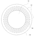
도 1은 본 발명의 바람직한 실시예에 따른 코깅 토크 저감을 위한 홈이 형성된 회전자를 구비한 전동기의 전체 구성도,
도 2는 고정자 철심의 평면도,
도 3은 회전자 철심의 평면도,
도 4는 회전자 철심에 형성된 홈의 위치와 크기를 도시한 도면,
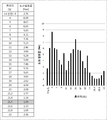
도 5는 홈이 형성된 회전자의 회전각에 따른 코깅 토크 변화를 도시한 그래프,
도 6는 회전자 철심에 형성된 홈의 각도에 따른 토크 실효 값을 도시한 도면,
도 7는 회전자의 중심점에서 회전자 철심에 형성된 홈의 중심까지 거리에 따른 토크 실효 값을 도시한 도면,
도 8은 회전자 철심에 형성된 홈의 반경에 따른 토크 실효 값을 도시한 도면이다.1 is an overall configuration diagram of an electric motor having a rotor with grooves for reducing cogging torque according to a preferred embodiment of the present invention;
2 is a plan view of the stator core,
3 is a plan view of the rotor iron core,
4 is a view showing a position and a size of a groove formed in a rotor iron core,
FIG. 5 is a graph showing changes in cogging torque according to the rotation angle of the grooved rotor,
6 is a graph showing the torque effective value according to the angle of the groove formed in the rotor iron core,
7 is a graph showing torque effective values according to the distance from the center of the rotor to the center of the groove formed in the rotor iron core,
8 is a graph showing the torque effective value according to the radius of the groove formed in the rotor iron core.
이하, 본 발명의 바람직한 실시예를 첨부된 도면들을 참조하여 상세히 설명한다. 우선 각 도면의 구성 요소들에 참조 부호를 부가함에 있어서, 동일한 구성 요소들에 대해서는 비록 다른 도면상에 표시되더라도 가능한 한 동일한 부호를 가지도록 하고 있음에 유의해야 한다. 또한, 본 발명을 설명함에 있어, 관련된 공지 구성 또는 기능에 대한 구체적인 설명이 본 발명의 요지를 흐릴 수 있다고 판단되는 경우에는 그 상세한 설명은 생략한다. 또한, 이하에서 본 발명의 바람직한 실시예를 설명할 것이나, 본 발명의 기술적 사상은 이에 한정하거나 제한되지 않고 당업자에 의해 변형되어 다양하게 실시될 수 있음은 물론이다.Hereinafter, preferred embodiments of the present invention will be described in detail with reference to the accompanying drawings. In the drawings, the same reference numerals are used to designate the same or similar components throughout the drawings. In the following description of the present invention, a detailed description of known functions and configurations incorporated herein will be omitted when it may make the subject matter of the present invention rather unclear. In addition, the preferred embodiments of the present invention will be described below, but it is needless to say that the technical idea of the present invention is not limited thereto and can be variously modified by those skilled in the art.
도 1은 본 발명의 바람직한 실시예에 따른 코깅 토크 저감을 위한 홈이 형성된 회전자를 구비한 전동기의 전체 구성도, 도 2는 고정자 철심의 평면도, 도 3은 회전자 철심의 평면도, 도 4는 회전자 철심에 형성된 홈의 위치와 크기를 도시한 도면, 도 5는 홈이 형성된 회전자의 회전각에 따른 코깅 토크 변화를 도시한 그래프, 도 6는 회전자 철심에 형성된 홈의 각도에 따른 토크 실효 값을 도시한 도면, 도 7는 회전자의 중심점에서 회전자 철심에 형성된 홈의 중심까지 거리에 따른 토크 실효 값을 도시한 도면, 도 8은 회전자 철심에 형성된 홈의 반경에 따른 토크 실효 값을 도시한 도면이다.FIG. 2 is a plan view of a stator iron core, FIG. 3 is a plan view of a rotor iron core, and FIG. 4 is a plan view of the iron core of the rotor core according to a preferred embodiment of the present invention. FIG. 5 is a graph showing the change in cogging torque according to the rotation angle of the rotor with the grooves formed thereon, FIG. 6 is a graph showing the torque according to the angle of the groove formed in the rotor iron core, Fig. 7 is a diagram showing the torque effective value according to the distance from the center of the rotor to the center of the groove formed in the rotor iron core, Fig. 8 is a graph showing the torque rms value according to the radius of the groove formed in the rotor iron core Fig.
본 발명의 따른 코깅 토크 저감을 위한 홈이 형성된 회전자를 구비한 전동기는 고정자 철심의 슬롯에 권취된 코일에 전류를 인가하면, 코일에서의 극성이 순차로 변화되면서 회전자 철심에 매립된 다수 개의 영구자석을 포함한 자성체에 의한 마그넷 토크(Magnet Torque) 및 자기저항 토크(Reluctance Torque)를 이용하여 회전자 철심을 구동시키는 매립형 영구자석 전동기의 일종이다.According to the present invention, when an electric current is applied to a coil wound on a slot of a stator core, a polarity of the coil is changed in order, and a plurality of coils Type permanent magnet motor that drives a rotor iron core by using a magnet torque and a reluctance torque by a magnetic body including a permanent magnet.
본 발명의 바람직한 실시예에 따른 코깅 토크 저감을 위한 홈이 형성된 회전자를 구비한 전동기는, 도 1 내지 도 4를 참조하면, 고정자 철심(10)(Stator Core), 회전자 철심(40)(Rotor Core), 자성체(50)(Magnet)를 포함하여 이루어진다.Referring to FIGS. 1 to 4, an electric motor including a rotor having grooves for reducing cogging torque according to a preferred embodiment of the present invention includes a
원형의 고정자 철심(10)은 도 1 및 도 2를 참조하면, 외주면에 길이방향으로 전동기의 하우징 내측과 용접하여 고정하기 위한 다수의 용접홈(12)이 소정간격 이격되어 형성된다. Referring to FIGS. 1 and 2, the
또한, 통상적인 전동기와 같이 중심부에 아래의 회전자 철심(40)이 삽입되기 위한 관통공(14)이 형성되며, 외측 원주면을 따라 소정간격으로 다수의 슬롯(16)이 형성된다.A
원형의 회전자 철심(40)은 도 3을 참조하면, 고정자 철심(10)의 중심부 관통공(14) 내측에서 회전이 가능하게 수용된다.Referring to FIG. 3, the circular
회전자 철심(20)에는 내측 중심부에 전동기의 회전축이 삽입되어 고정될 수 있도록 양측에 대칭되게 복수의 축 고정홈(22)이 구비된 축 삽입공(24)이 형성된다.The
한편, 회전자 철심(20)에는 아래의 영구자석을 포함한 자성체(50)가 매립될 수 있도록 다수의 자성체 홀이 형성된다.On the other hand, a plurality of magnetic body holes are formed in the
도 3을 참조하면, 제1 자성체 홀(28)은 일측 단이 상호 간에 인접하여 위치하고, 타측 단에는 돌출된 에어갭이 형성되며, 중심부를 기준으로 "V" 자 형태로 상호 좌측 및 우측이 대칭되게 쌍으로 형성되며, 이 쌍은 원주면 가장자리를 따라 다수 개가 형성된다.Referring to FIG. 3, the first
회전자 철심(40)의 제2 자성체 홀(30)은 대칭되는 제1 자성체 홀(28)의 중심부의 하방에 위치하며 원주 방향을 따라 제1 자성체 홀(28)이 형성된 위치마다 각 하나씩 다수 개가 형성된다. The second
회전자 철심의 제3 자성체 홀(32)은 일측 단이 제2 자성체 홀(28)의 양측 단에 인접하고, 타측 단에는 돌출된 에어갭이 형성되고, 제2 자성체 홀을 중심으로 "V" 자 형태로 상호 좌측 및 우측이 대칭되게 형성되며, 제2 자성체 홀을 따라 원주방향으로 다수 개가 형성된다.The third
회전자 철심(40)의 각 자성체 홀은 영구자석을 포함한 자성체가 분산되도록 배치하여 자속 경로를 분산시키는 효과가 있으며, 회전자 철심의 한정된 공간에 많은 자성체가 수용될 수 있도록 한다.Each magnetic hole of the
한편, 제1 자성체 홀과 제3 자성체 홀에 형성된 에어갭은 자성체의 자속에 영향을 주는 역할을 수행한다.On the other hand, the air gap formed in the first magnetic body hole and the third magnetic body hole plays a role in influencing the magnetic flux of the magnetic body.
또한, 도 3 및 도 4를 참조하면, 전동기의 코깅 토크를 감소시키기 위해 회전자 철심(40)의 외주 단에는 측면 길이방향으로 노치 형태의 다수의 홈(34)이 원주방향을 따라 소정간격 이격되어 형성된다. 3 and 4, in order to reduce the cogging torque of the electric motor, a plurality of
이 노치 형태의 홈(34)은 도 5를 참조하면, 회전자 철심(40)에 형성되는 그 위치와 크기에 따라 코깅 토크의 실효값에 영향을 미친다.Referring to FIG. 5, the
본 발명의 바람직한 실시예에 따른 전동기의 회전자 철심(40)에 형성된 노치 형태의 홈의 위치와 크기는 도 4를 참조하면, 회전자의 외주단에 노치 형태로 형성된 홈은 회전자의 중심점을 기준으로 홈의 중심부와 제1 자성체 홀의 중심부 사이의 홈 각도가 21.5˚가 되는 곳에 위치하고, 회전자의 중심점에서 홈의 중심까지의 거리는 95 mm이며, 홈의 반경이 6 mm인 일 때 전동기가 최소한의 코깅토크 실효 값을 가진다. Referring to FIG. 4, the notch-shaped grooves formed in the
또한, 본 발명의 바람직한 실시예에 따른 회전자 철심(40)에 형성된 노치 형태의 홈의 위치와 크기는 아래에 서술된 실험에 의한 데이터의 획득을 통해 확인할 수 있다.In addition, the position and size of the notched groove formed in the
본 발명의 바람직한 실시예에 따른 전동기의 크기는, 고정자 철심(10)의 외경은 306.50mm, 내경은 182.0mm 이고, 회전자 철심(40)의 외경은 81.5mm, 내경은 90.0mm로 하여 실험을 수행하였다.In the motor according to the preferred embodiment of the present invention, the outer diameter of the
먼저, 회전자 철심의 외주단에서 측면 길이방향으로 노치 형태로 형성된 홈(34)의 위치를 설정하기 위한 홈의 각도는 도 4를 참조하면, 회전자 철심(40)의 중심점(원점)을 기준으로 홈의 중심부와 제1 자성체 홀의 중심부 사이에 형성된 각도로 표현된다.Referring to FIG. 4, the angle of the groove for setting the position of the
도 6을 참조하면, 이 홈의 각도에 따라 토크 실효 값이 달라지며, 그 홈의 각도가 21.5˚일 때 될 때 토크 실효 값이 1.09 Nm로 최소가 됨을 알 수 있다.Referring to FIG. 6, the effective torque value varies depending on the angle of the groove, and when the angle of the groove is 21.5 degrees, the effective torque value is minimized to 1.09 Nm.
또한, 회전자 철심의 중심점(원점)에서 홈의 중심부까지의 거리는 도 4에 도시한 바와 같이 표현된다.The distance from the center point (origin) of the rotor iron core to the center of the groove is expressed as shown in Fig.
도 7을 참조하면, 회전자 철심의 중심점에서 홈의 중심부까지의 거리가 95 mm 일 때 토크 실효 값이 1.09 Nm로 최소가 됨을 알 수 있다.Referring to FIG. 7, when the distance from the center of the rotor iron core to the center of the groove is 95 mm, the torque effective value is minimized to 1.09 Nm.
또한, 홈의 반경은 도 4에 도시한 바와 같이 회전자 철심의 중심점(원점)에서 홈의 중심부까지의 거리에서 형성된 원의 반경으로 표현된다.Further, the radius of the groove is expressed by a radius of a circle formed at a distance from the center point (origin) of the rotor iron core to the center of the groove as shown in Fig.
도 8을 참조하면, 회전자 철심의 중심점에서 홈의 중심부까지의 거리에서 형성된 홈의 반경이 6 mm 일 때 토크 실효 값이 1.09 Nm로 최소가 됨을 알 수 있다.Referring to FIG. 8, when the radius of the groove formed at the distance from the central point of the rotor iron core to the center of the groove is 6 mm, the torque effective value is minimized to 1.09 Nm.
한편, 자성체(50)는 회전자 철심(40)에 형성된 제1 자성체 홀, 제2 자성체 홀 및 제3 자성체 홀 각각에 매립되어 고정자 철심의 코일(미도시)에 전류를 인가하면, 코일에서의 극성이 순차로 변화되면서 회전자 철심에 매립된 영구자석 등을 포함한 자성체와 반발력 및 흡인력을 발생시키고, 이에 따른 원심력에 의해 회전 구동력을 발생시킨다.On the other hand, when the
이상의 설명은 본 발명의 기술 사상을 예시적으로 설명한 것에 불과한 것으로서, 본 발명이 속하는 기술 분야에서 통상의 지식을 가진 자라면 본 발명의 본질적인 특성에서 벗어나지 않는 범위 내에서 다양한 수정, 변경 및 치환이 가능할 것이다. 따라서, 본 발명에 개시된 실시예 및 첨부된 도면들은 본 발명의 기술 사상을 한정하기 위한 것이 아니라 설명하기 위한 것이고, 이러한 실시예 및 첨부된 도면에 의하여 본 발명의 기술 사상의 범위가 한정되는 것은 아니다. 본 발명의 보호 범위는 아래의 청구범위에 의하여 해석되어야 하며, 그와 동등한 범위 내에 있는 모든 기술 사상은 본 발명의 권리범위에 포함되는 것으로 해석되어야 할 것이다.It will be apparent to those skilled in the art that various modifications, substitutions and substitutions are possible, without departing from the scope and spirit of the invention as disclosed in the accompanying claims. will be. Therefore, the embodiments disclosed in the present invention and the accompanying drawings are intended to illustrate and not to limit the technical spirit of the present invention, and the scope of the technical idea of the present invention is not limited by these embodiments and the accompanying drawings . The scope of protection of the present invention should be construed according to the following claims, and all technical ideas within the scope of equivalents should be construed as falling within the scope of the present invention.
10 - 고정자 철심
12 - 용접홈
14 - 관통공
16 - 슬롯
22 - 고정홈
24 - 삽입공
26 - 에어갭
28 - 제1 자성체 홀
30 - 제2 자성체 홀
32 - 제3 자성체 홀
34 - 홈
40 - 회전자 철심
50 - 자성체
10 - Stator core 12 - Welding groove
14 - Through hole 16 - Slot
22 - Fixing groove 24 - Insertion hole
26 - Air gap 28 - First magnetic material hole
30 - Second magnetic body hole 32 - Third magnetic body hole
34 - Groove 40 - Rotor iron core
50 - magnetic substance
Claims (2)
내측 중심부에 회전축이 삽입되어 고정될 수 있도록 양측에 대칭되게 복수의 축 고정홈이 구비된 축 삽입공이 형성되고,
일측 단은 상호 인접하고, 타측 단에는 돌출된 에어갭이 형성되며 중심부를 기준으로 "V" 자 형태로 상호 대칭되게 쌍으로 원주면 가장자리를 따라 다수의 제1 자성체 홀이 형성되며,
대칭되는 제1 자성체 홀의 중심부의 하방에 다수의 제2 자성체 홀이 형성되고,
일측 단이 제2 자성체 홀의 양측 단에 인접하고, 타측 단에는 돌출된 에어갭이 형성되어 제2 자성체 홀을 중심으로 "V" 자 형태로 상호 대칭되게 다수의 제3 자성체 홀이 형성되며,
외주 단에는 측면 길이방향으로 노치 형태의 다수의 홈이 원주방향을 따라 소정간격 이격되어 형성되고,
고정자 철심의 중심부 관통공 내측에 수용되는 원형의 회전자 철심; 및
회전자 철심에 형성된 제1 자성체 홀, 제2 자성체 홀 및 제3 자성체 홀 각각에 매립되는 자성체
를 포함하는, 코깅 토크 저감을 위한 홈이 형성된 회전자를 구비한 전동기.A circular stator iron core having a plurality of welding grooves spaced apart from each other by a predetermined distance on an outer circumferential surface thereof, a through hole formed in the center thereof, and a plurality of slots formed at predetermined intervals along the outer circumferential surface;
A shaft insertion hole having a plurality of shaft fixing grooves symmetrically formed on both sides so that a rotary shaft can be inserted and fixed to an inner center portion,
And a plurality of first magnetic body holes are formed along the circumferential surface of the pair in mutually symmetrical shapes with a "V" shape on the basis of the central portion,
A plurality of second magnetic body holes are formed below the central portion of the symmetrical first magnetic body holes,
And a plurality of third magnetic body holes are formed symmetrically with respect to the second magnetic body holes in a "V" shape, and a plurality of second magnetic body holes are formed on the other end of the third magnetic body holes,
A plurality of grooves in the shape of a notch are formed at the outer circumferential end at predetermined intervals along the circumferential direction,
A circular rotor iron core accommodated inside the central through hole of the stator core; And
A magnetic body embedded in each of the first magnetic body holes, the second magnetic body holes and the third magnetic body holes formed in the rotor iron core,
And a rotor having a groove formed therein for cogging torque reduction.
회전자 철심의 외주단에서 측면 길이방향의 노치 형태로 형성된 홈은 회전자 철심의 중심점을 기준으로 홈의 중심부와 제1 자성체 홀의 중심부 사이의 홈 각도가 21.5˚가 되는 곳에 위치하고,
회전자 철심의 중심점에서 홈의 중심부까지의 거리는 95 mm이며,
홈의 반경이 6 mm인 것
을 특징으로 하는, 코깅 토크 저감을 위한 홈이 형성된 회전자를 구비한 전동기.The method according to claim 1,
The groove formed in the shape of a notch in the side lengthwise direction at the outer peripheral end of the rotor iron core is located at a position where the groove angle between the center of the groove and the center of the first magnetic body hole is 21.5 DEG with respect to the center point of the rotor iron core,
The distance from the center of the rotor iron core to the center of the groove is 95 mm,
A groove having a radius of 6 mm
And a rotor having a groove formed therein for cogging torque reduction.
Priority Applications (2)
| Application Number | Priority Date | Filing Date | Title |
|---|---|---|---|
| KR1020150151136A KR20170050079A (en) | 2015-10-29 | 2015-10-29 | Motor With Notched Rotor For Cogging Torque Reduction |
| PCT/KR2015/011533 WO2017073813A1 (en) | 2015-10-29 | 2015-10-30 | Motor comprising rotor on which groove for reducing cogging torque is formed |
Applications Claiming Priority (1)
| Application Number | Priority Date | Filing Date | Title |
|---|---|---|---|
| KR1020150151136A KR20170050079A (en) | 2015-10-29 | 2015-10-29 | Motor With Notched Rotor For Cogging Torque Reduction |
Publications (1)
| Publication Number | Publication Date |
|---|---|
| KR20170050079A true KR20170050079A (en) | 2017-05-11 |
Family
ID=58630320
Family Applications (1)
| Application Number | Title | Priority Date | Filing Date |
|---|---|---|---|
| KR1020150151136A KR20170050079A (en) | 2015-10-29 | 2015-10-29 | Motor With Notched Rotor For Cogging Torque Reduction |
Country Status (2)
| Country | Link |
|---|---|
| KR (1) | KR20170050079A (en) |
| WO (1) | WO2017073813A1 (en) |
Cited By (3)
| Publication number | Priority date | Publication date | Assignee | Title |
|---|---|---|---|---|
| KR20190128370A (en) * | 2018-05-08 | 2019-11-18 | 엘지전자 주식회사 | Rotor assembly |
| KR20200014040A (en) * | 2018-07-31 | 2020-02-10 | 한국생산기술연구원 | Motor of motch structure for torque ripple |
| KR20200106553A (en) | 2018-03-16 | 2020-09-14 | 그리 일렉트릭 어플라이언시즈, 인코포레이티드 오브 주하이 | Rotor structure, permanent magnet auxiliary synchronous magnetoresistive motor and electric vehicle |
Families Citing this family (1)
| Publication number | Priority date | Publication date | Assignee | Title |
|---|---|---|---|---|
| JP2022107335A (en) * | 2021-01-08 | 2022-07-21 | トヨタ自動車株式会社 | Motor magnet oil-cooled structure and motor |
Family Cites Families (5)
| Publication number | Priority date | Publication date | Assignee | Title |
|---|---|---|---|---|
| JP2002078259A (en) * | 2000-08-31 | 2002-03-15 | Yamaha Motor Co Ltd | Permanent magnet rotor |
| US7498708B2 (en) * | 2004-10-26 | 2009-03-03 | Kollmorgen Corporation | Design of the magnet and webs in interior permanent magnet rotors |
| EP2083503A3 (en) * | 2008-01-22 | 2017-03-29 | LG Electronics Inc. | Brushless direct current motor |
| JP2013162556A (en) * | 2012-02-01 | 2013-08-19 | Suzuki Motor Corp | Electric rotary machine |
| JP6379462B2 (en) * | 2013-09-03 | 2018-08-29 | 富士電機株式会社 | Permanent magnet embedded rotary electric machine |
-
2015
- 2015-10-29 KR KR1020150151136A patent/KR20170050079A/en not_active Application Discontinuation
- 2015-10-30 WO PCT/KR2015/011533 patent/WO2017073813A1/en active Application Filing
Cited By (4)
| Publication number | Priority date | Publication date | Assignee | Title |
|---|---|---|---|---|
| KR20200106553A (en) | 2018-03-16 | 2020-09-14 | 그리 일렉트릭 어플라이언시즈, 인코포레이티드 오브 주하이 | Rotor structure, permanent magnet auxiliary synchronous magnetoresistive motor and electric vehicle |
| US11689071B2 (en) | 2018-03-16 | 2023-06-27 | Gree Electric Appliances, Inc. Of Zhuhai | Rotor structure, permanent magnet auxiliary synchronous reluctance motor, and electric vehicle |
| KR20190128370A (en) * | 2018-05-08 | 2019-11-18 | 엘지전자 주식회사 | Rotor assembly |
| KR20200014040A (en) * | 2018-07-31 | 2020-02-10 | 한국생산기술연구원 | Motor of motch structure for torque ripple |
Also Published As
| Publication number | Publication date |
|---|---|
| WO2017073813A1 (en) | 2017-05-04 |
Similar Documents
| Publication | Publication Date | Title |
|---|---|---|
| US20070018520A1 (en) | Motor/generator to reduce cogging torque | |
| JP2013055872A (en) | Switched reluctance motor | |
| JP2008206308A (en) | Permanent-magnet rotating electric machine | |
| JP2014050211A (en) | Permanent magnet rotary electric machine | |
| US20170338726A1 (en) | Polyphase motor having an alternation of permanent magnets and salient poles | |
| CN107852045B (en) | Rotary motor | |
| US20130278106A1 (en) | Rotor assembly | |
| US10236732B2 (en) | Inductor type rotary motor | |
| KR20170050079A (en) | Motor With Notched Rotor For Cogging Torque Reduction | |
| KR20140088267A (en) | Permanent magnet synchronous motor rotor with a structure providing the high torque | |
| KR100548278B1 (en) | Magnet for hybrid induction motor and magnetization method thereof | |
| JP2006087283A (en) | Permanent magnet type rotation motor | |
| WO2020194390A1 (en) | Rotating electric machine | |
| JP7047337B2 (en) | Permanent magnet type rotary electric machine | |
| JP4855747B2 (en) | Permanent magnet type reluctance rotating electric machine | |
| WO2021149473A1 (en) | Magnetic geared rotary electric machine | |
| JP6083640B2 (en) | Permanent magnet embedded motor | |
| JP2007143331A (en) | Permanent-magnet-embedded rotor | |
| JP2018085877A (en) | Rotary electric machine | |
| JP2005130689A (en) | Rotating electric machine | |
| JP2005278268A (en) | Permanent magnet type motor | |
| JP6012046B2 (en) | Brushless motor | |
| JP6201405B2 (en) | Rotating electric machine | |
| KR101228454B1 (en) | Self magnetizing motor | |
| JP2012060709A (en) | Permanent magnet motor |
Legal Events
| Date | Code | Title | Description |
|---|---|---|---|
| A201 | Request for examination | ||
| E902 | Notification of reason for refusal | ||
| E601 | Decision to refuse application |