JP2010022002A - Method for quantizing of signal value and quantizer - Google Patents
Method for quantizing of signal value and quantizer Download PDFInfo
- Publication number
- JP2010022002A JP2010022002A JP2009164615A JP2009164615A JP2010022002A JP 2010022002 A JP2010022002 A JP 2010022002A JP 2009164615 A JP2009164615 A JP 2009164615A JP 2009164615 A JP2009164615 A JP 2009164615A JP 2010022002 A JP2010022002 A JP 2010022002A
- Authority
- JP
- Japan
- Prior art keywords
- quantization
- signal
- value
- numerical range
- communication device
- Prior art date
- Legal status (The legal status is an assumption and is not a legal conclusion. Google has not performed a legal analysis and makes no representation as to the accuracy of the status listed.)
- Granted
Links
Images


Classifications
-
- H—ELECTRICITY
- H03—ELECTRONIC CIRCUITRY
- H03M—CODING; DECODING; CODE CONVERSION IN GENERAL
- H03M1/00—Analogue/digital conversion; Digital/analogue conversion
- H03M1/12—Analogue/digital converters
- H03M1/1235—Non-linear conversion not otherwise provided for in subgroups of H03M1/12
-
- H—ELECTRICITY
- H03—ELECTRONIC CIRCUITRY
- H03M—CODING; DECODING; CODE CONVERSION IN GENERAL
- H03M1/00—Analogue/digital conversion; Digital/analogue conversion
- H03M1/66—Digital/analogue converters
- H03M1/664—Non-linear conversion not otherwise provided for in subgroups of H03M1/66
Abstract
Description
〔技術分野〕
実施形態は、概して、信号値を量子化する方法および量子化器に関する。
〔Technical field〕
Embodiments generally relate to methods and quantizers for quantizing signal values.
〔背景〕
無線通信システムでは、アナログからデジタルおよびデジタルからアナログへの変換が行われる。本質的にこれらの変換では、信号値の量子化が行われる。用いられる量子化のタイプおよび設計は、量子化誤差(ひいては信号対雑音比)と、量子化を行う回路の電力消費とに影響を及ぼす。少ない電力消費および少ない量子化誤差が望まれることから、改善された量子化方法が必要とされている。
〔background〕
In wireless communication systems, analog to digital and digital to analog conversions are performed. In essence, these transformations involve quantization of signal values. The type and design of quantization used affects the quantization error (and hence the signal to noise ratio) and the power consumption of the circuit that performs the quantization. Since low power consumption and low quantization error are desired, an improved quantization method is needed.
〔図面の簡単な説明〕
全ての図面において、同様の参照符号は概して同一の箇所を示す。これらの図面は、互いに相対的な縮尺になっているとは限らず、代わりに、様々な実施形態の原理を示す箇所が概して強調されている。以下の説明では、様々な実施形態について図面を参照しながら説明する。
図1は、アップリンクおよびダウンリンク用の3GPP LTE規格の枠組み内における線形量子化器の伝達関数を示す図である。
図2は、典型的なLTE構造内におけるアップリンク信号およびダウンリンク信号の正規化された確率密度関数(PDF)を有する図表を示す図である。
図3は、一実施形態に係る通信システムを示す図である。
図4は、無線インターフェースを介して受信または伝送される信号の信号値を量子化する方法を示す図である。
図5は、通信装置から受信された信号または通信装置へ伝送される信号を量子化する方法を示す図である。
図6は、一実施形態に係る信号処理構成を示す図である。
図7は、一実施形態に係る信号処理構成を示す図である。
図8は、マルチパス環境用の信号例の正規化された確率密度関数を有する図表を示す図である。
図9は、LTE構造内におけるアップリンク信号およびダウンリンク信号の正規化された確率密度関数を有する3つの図表を示す図である。
図10は、一実施形態に係る量子化器の伝達関数を有する図表を示す図である。
図11は、一実施形態に係るフローチャートを示す図である。
図12は、一実施形態に係る機能グラフを示す図である。
図13は、一実施形態に係るフローチャートを示す図である。
[Brief description of the drawings]
Like reference symbols generally refer to the same parts throughout the drawings. These drawings are not necessarily drawn to scale relative to each other, but instead are emphasized generally to illustrate the principles of various embodiments. In the following description, various embodiments will be described with reference to the drawings.
FIG. 1 is a diagram illustrating a transfer function of a linear quantizer within the framework of the 3GPP LTE standard for uplink and downlink.
FIG. 2 is a diagram illustrating a diagram with normalized probability density functions (PDF) of uplink and downlink signals in a typical LTE structure.
FIG. 3 is a diagram illustrating a communication system according to an embodiment.
FIG. 4 is a diagram illustrating a method of quantizing a signal value of a signal received or transmitted via a wireless interface.
FIG. 5 is a diagram illustrating a method of quantizing a signal received from a communication device or a signal transmitted to the communication device.
FIG. 6 is a diagram illustrating a signal processing configuration according to an embodiment.
FIG. 7 is a diagram illustrating a signal processing configuration according to an embodiment.
FIG. 8 is a diagram illustrating a chart having a normalized probability density function of an example signal for a multipath environment.
FIG. 9 shows three diagrams with normalized probability density functions for uplink and downlink signals in the LTE structure.
FIG. 10 is a diagram illustrating a diagram having a transfer function of a quantizer according to an embodiment.
FIG. 11 is a diagram illustrating a flowchart according to an embodiment.
FIG. 12 is a diagram illustrating a function graph according to an embodiment.
FIG. 13 is a diagram illustrating a flowchart according to an embodiment.
〔説明〕
移動体通信システムでは、情報を交換するために、移動体端末(ユーザ装置(User Equipment;UE)とも称される)と基地局との間において無線リンクが使用される。このため、交換される情報(例えば、テキストメッセージ、ビデオクリップ等)は、無線伝送に適した無線信号に変換される。
〔Explanation〕
In a mobile communication system, a radio link is used between a mobile terminal (also referred to as user equipment (UE)) and a base station to exchange information. For this reason, information to be exchanged (for example, a text message, a video clip, etc.) is converted into a radio signal suitable for radio transmission.
典型的には、そのような変換処理は以下の工程に分割されうる(記載されている順序は伝送のための順序であって、受信には逆の順序が適用される):
i)ベースバンド処理(チャネル符号化等の、伝送されるデータのデジタル処理を含む)、
ii)伝送のためのデジタル/アナログ(D/A)変換(または、受信のためのアナログ/デジタル(A/D)変換)、および、
iii)無線周波数(RF)処理。
Typically, such a conversion process may be divided into the following steps (the order described is the order for transmission and the reverse order is applied for reception):
i) Baseband processing (including digital processing of transmitted data, such as channel coding),
ii) digital / analog (D / A) conversion for transmission (or analog / digital (A / D) conversion for reception), and
iii) Radio frequency (RF) processing.
一実施形態では、上記第2の工程、すなわちA/D変換およびD/A変換に焦点が当てられる。 In one embodiment, the second step is focused on: A / D conversion and D / A conversion.
A/D部品およびD/A部品の電力消費は、それらの入力信号の特性およびそれらの量子化誤差のサイズに密接に関連しているため、例えば移動体端末および基地局において、A/D部品およびD/A部品の電力消費を最小限にすることを目的とする場合、以下の問題が生じる:
1)i)特定の平均量子化誤差レベルでの電力消費を最小限にするために、ii)特定の電力消費での平均量子化誤差を最小限にするために、または、iii)これら2つを混ぜ合わせた目的のために、基地局および移動体端末の両方におけるA/D部品およびD/A部品の最適な設定をどのように選択するのか。
Since the power consumption of A / D components and D / A components is closely related to the characteristics of their input signals and the size of their quantization error, for example in mobile terminals and base stations, A / D components And when aiming to minimize the power consumption of D / A components, the following problems arise:
1) i) to minimize power consumption at a specific average quantization error level, ii) to minimize average quantization error at a specific power consumption, or iii) these two How to select the optimal settings for A / D components and D / A components in both the base station and the mobile terminal for the purpose of mixing
2)移動体通信システム内で生じる入力信号特性を考慮に入れながら、最適なA/D量子化戦略、および/または、D/A量子化戦略(すなわち、A/D部品(および/または、D/A部品)の入力と出力との最適な関係)をどのように選択するのか。 2) Optimum A / D quantization strategy and / or D / A quantization strategy (ie A / D components (and / or D), taking into account the input signal characteristics occurring within the mobile communication system How to select the optimal relationship between the input and output of / A part).
一実施形態では、3GPP 長期発展(Long Term Evolution;LTE)規格の枠組みに準拠した移動体無線通信システムが使用される(しかし別の実施形態では、任意の他の移動体無線通信規格に準拠した他の任意の移動体無線通信技術が提供されうる)。例えば、一実施形態では、(逆フーリエ変換に基づく)従来の直交周波数分割多重(Orthogonal Frequency Division Multiplexing;OFDM)変調器と、フーリエ変換係数を含むプリコーディング行列とを組み合わせた、特別な3GPP LTEアップリンク変調方式のための量子化方法が提供されうる。 In one embodiment, a mobile radio communication system that conforms to the framework of the 3GPP Long Term Evolution (LTE) standard is used (but in another embodiment, it complies with any other mobile radio communication standard). Any other mobile radio communication technology can be provided). For example, in one embodiment, a special 3GPP LTE up-combination that combines a conventional Orthogonal Frequency Division Multiplexing (OFDM) modulator (based on an inverse Fourier transform) and a precoding matrix that includes Fourier transform coefficients. A quantization method for a link modulation scheme may be provided.
入力信号特性とは無関係な量子化に対しては、標準的な線形量子化方法が用いられうる。従って、量子化のステップサイズは、例えば入力信号電力に応じて選択されうる。 For quantization independent of input signal characteristics, standard linear quantization methods can be used. Therefore, the quantization step size can be selected according to, for example, the input signal power.
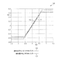
図1は、アップリンクおよびダウンリンク用の3GPP LTE規格の枠組み内における線形量子化器の伝達関数を示している。図表100では、入力値(x軸103に沿って示されている)と出力値(y軸104に沿って示されている)との関係が、例えばSC−OFDMに準拠した信号の入力値に用いられる線形量子化(曲線102)と、例えばOFDMAに準拠した信号の入力値に用いられる線形量子化(曲線101)とに対して示されている。
FIG. 1 shows the transfer function of a linear quantizer within the framework of the 3GPP LTE standard for uplink and downlink. In the
アップリンクおよびダウンリンクの最適なステップサイズは、複数の異なる信号特性ゆえに、同一の電力レベルにおいて異なりうる。分かり易くするために、図1には16の量子化ステップが示されている。 The optimal uplink and downlink step sizes can be different at the same power level due to multiple different signal characteristics. For the sake of clarity, FIG. 1 shows 16 quantization steps.
鍵となる問題は、A/D変換器、および/または、D/A変換器における固有の量子化への入力信号値の分配に見られる。 A key problem is seen in the distribution of input signal values to the A / D converter and / or inherent quantization in the D / A converter.
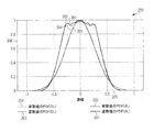
図2は、典型的なLTE構造内におけるアップリンク信号およびダウンリンク信号の正規化された確率密度関数(probability density function;PDF)を示す図表200を示している。電力レベルは、用いられる信号キャリアの平均電力が1となるように選択される。 FIG. 2 shows a diagram 200 illustrating the normalized probability density function (PDF) of uplink and downlink signals within a typical LTE structure. The power level is selected such that the average power of the signal carrier used is 1.
x軸205に沿って、信号値が示されている。y軸206に沿って、確率が示されている。図表200は、アップリンク伝送信号の虚数値(曲線201)、アップリンク伝送信号の実数値(曲線202)、ダウンリンク伝送信号の虚数値(曲線203)、およびダウンリンク伝送信号の実数値(曲線204)の確率分布関数を示している。
A signal value is shown along the
確率分布関数(probability distribution function;PDF)は、負の無限大から正の無限大までの積分が1と等しくなる関数である。PDFを示す図では、PDFは、最大値が1となるようにスケールされている。これには2つの理由がある:i)図の解釈が促進される、および、ii)数値的に不安定となりうる、ひいては誤りうる積分の数値計算が回避される(すなわち、誤る可能性のある計算結果が回避される)。従って、適用可能な場合であれば、「確率密度関数」という用語は、このように正規化された確率密度関数、すなわち「正規化された確率密度関数」を言う。さらに、正規化された確率密度関数が一実施形態に従って生成または使用される場合、これはまた、(正規の、すなわち、積分1を有する)確率密度関数が生成または使用されること、およびその逆も意味する。 The probability distribution function (PDF) is a function in which the integral from negative infinity to positive infinity is equal to 1. In the figure showing PDF, the PDF is scaled so that the maximum value is 1. There are two reasons for this: i) facilitates interpretation of the figure, and ii) avoids numerical calculations of integrals that can be numerically unstable and thus erroneous (ie, can be erroneous). Calculation results are avoided). Thus, where applicable, the term “probability density function” refers to a probability density function thus normalized, ie, “normalized probability density function”. Furthermore, if a normalized probability density function is generated or used according to one embodiment, this also means that a probability density function (normal, ie with integral 1) is generated or used, and vice versa. Also means.
図2に示されている分布グラフからは、線形量子化の使用の特性が分かる:
1)平均二乗量子化誤差を最小限にするためには、量子化範囲にわたって入力信号を一定に分配する線形量子化法が最適である。しかし、図2に示されているような一定でないPDFは、複数の異なる量子化要件を生じさせる:量子化誤差は、最も頻繁に生じる数値範囲では可能な限り小さくなければならない。他方で、量子化誤差制限を、非常に稀にしか生じない数値範囲では軽減することができる。従って、線形量子化に基づく標準的な方法によって、準最適な解決策がもたらされる。この直観的な考えは、一実施形態において、最適な量子化ステップの順序を厳密に誘導する基礎として用いられる。固定数の量子化ステップにおいて、最適化された量子化ステップ設定を用いて、より良好な雑音レベルを得ることができる。この最適化された量子化ステップ設定によって、場合によっては、必要とされる量子化ビット数を低減することもでき、これにより量子化を含む部品の電力消費を低減することができる。
The distribution graph shown in FIG. 2 shows the characteristics of using linear quantization:
1) In order to minimize the mean square quantization error, a linear quantization method that distributes the input signal uniformly over the quantization range is optimal. However, a non-constant PDF as shown in FIG. 2 gives rise to several different quantization requirements: the quantization error should be as small as possible in the most frequently occurring numerical range. On the other hand, the quantization error limit can be reduced in a numerical range that occurs very rarely. Thus, a standard method based on linear quantization provides a sub-optimal solution. This intuitive idea is used in one embodiment as a basis for rigorously deriving the optimal quantization step order. In a fixed number of quantization steps, a better noise level can be obtained using an optimized quantization step setting. This optimized quantization step setting can also reduce the number of required quantization bits in some cases, thereby reducing the power consumption of components including quantization.
2)従来、アップリンク信号およびダウンリンク信号には、同様の量子化タイプ(すなわち線形量子化)が使用されている。しかし、例えばLTEでは、図2に見られるように、確率分布はアップリンク信号とダウンリンク信号とでは異なる。従って、一実施形態によれば、以下の特別な構成が考慮される:
a)ユーザ装置(UE):A/D変換は、一実施形態では、ダウンリンク信号を受信するように適応される。最適な量子化ステップ順序の対応する選択は、例えば、図2に示されているようなダウンリンクPDFの形式に基づいている。標準的なOFDMシンボルでは、対応する実時間領域信号および虚時間領域信号のPDFは準ガウスである。他方、D/A変換は、一実施形態では、アップリンク信号を伝送するように適応される。このアップリンク信号は、例えば3GPP LTEアップリンク信号、または、3GPP LTEアップリンク信号に(その信号値分布に関して)特性が類似したアップリンク信号である。最適な量子化ステップ順序の選択は、例えば、上述のようなアップリンクPDFの形式に基づいている。このように上記例では、このPDFは、ゼロ付近の数値範囲(この例において使用される平均電力の約−0.3...+0.3)においてほぼ一定であり、その後急激に低下する。これは、一実施形態では、線形に近い量子化がほぼ一定の数値範囲に適した量子化として用いられる一方で、「より粗い」量子化(すなわち、量子化ステップ幅がより大きい量子化)が、一実施形態では、残りの値(すなわち、より大きい信号値)には十分であると考えられることを意味している。
2) Conventionally, similar quantization types (ie, linear quantization) are used for uplink and downlink signals. However, in LTE, for example, as seen in FIG. 2, the probability distribution is different between the uplink signal and the downlink signal. Thus, according to one embodiment, the following special configuration is considered:
a) User equipment (UE): A / D conversion is adapted to receive a downlink signal in one embodiment. The corresponding selection of the optimal quantization step order is based, for example, on the format of the downlink PDF as shown in FIG. For standard OFDM symbols, the corresponding real time and imaginary time domain PDFs are quasi-Gaussian. On the other hand, D / A conversion is adapted to transmit uplink signals in one embodiment. This uplink signal is, for example, a 3GPP LTE uplink signal or an uplink signal having characteristics similar to those of the 3GPP LTE uplink signal (with respect to its signal value distribution). The selection of the optimal quantization step order is based on the format of the uplink PDF as described above, for example. Thus, in the above example, this PDF is substantially constant in the numerical range near zero (about -0.3 ... + 0.3 of the average power used in this example), and then decreases rapidly. This is because, in one embodiment, near-linear quantization is used as quantization suitable for a substantially constant numerical range, while “coarsier” quantization (ie, quantization with a larger quantization step width) is used. In one embodiment, this means that the remaining value (ie, a larger signal value) is considered sufficient.
b)基地局(BS):A/D変換は、一実施形態では、アップリンク信号を受信するように適応され、D/Aは、ダウンリンク信号を伝送するように適応されうる。これは、一実施形態では、部品構成が、使用される量子化方法に関して、移動体端末に比べて逆に構成されていることを意味する。 b) Base Station (BS): A / D conversion may be adapted to receive uplink signals and D / A may be adapted to transmit downlink signals in one embodiment. This means that in one embodiment, the component configuration is reversed compared to the mobile terminal with respect to the quantization method used.
上述のように、A/D、および/または、D/Aの固有の(線形)量子化の典型的な実施は、例えば3GPP LTEの状況においては準最適であり、また、(特別に最適化された量子化と比較して)i)平均二乗量子化誤差が高くなり、およびii)量子化ビット数の要件が高くなり、これによって平均二乗量子化誤差目標を満たすための電力消費が高くなりうることが分かっている。 As mentioned above, the typical implementation of A / D and / or D / A inherent (linear) quantization is sub-optimal, for example in the 3GPP LTE context, and (specially optimized) I) higher mean square quantization error, and ii) higher quantization bit rate requirements, which results in higher power consumption to meet the mean square quantization error goal. I know that I can.
後者においては、A/D部品の電力消費は、典型的には、2を有効ビット数(effective number of bits;ENOB)で累乗した値に比例することに留意されたい。これは、追加の各ビットが、A/D部品の電力消費を約2倍にすることが予想されることを意味している。例えば、ENOBが11.2ビットで、20メガサンプル/秒を提供する適切な部品の予想されるA/D電力消費は、120mWでありうる。従って、ENOB要件の低減によって、数十mWの電力消費低下につながると予想される。 Note that in the latter, the power consumption of the A / D component is typically proportional to the value of 2 raised to the effective number of bits (ENOB). This means that each additional bit is expected to approximately double the power consumption of the A / D component. For example, the expected A / D power consumption of a suitable component that provides 20 megasamples / second with an ENOB of 11.2 bits may be 120 mW. Therefore, it is expected that reducing the ENOB requirement will lead to a reduction in power consumption of several tens of mW.
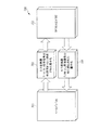
図3は、一実施形態に係る通信システムを示している。 FIG. 3 shows a communication system according to an embodiment.
本実施例における通信システムは、移動体無線通信システムである。移動体端末301は、例えばコアネットワーク304に結合された移動体無線通信ネットワーク302と通信しうる。この移動体無線通信ネットワークは、無線アクセスネットワーク303を含んでいる。上記移動体無線通信ネットワークは、基地局305を含みうる。移動体端末301は、無線信号を用いて基地局305とデータを交換する。これを行うために、移動体端末301は、無線周波数フロントエンド部品307(例えば無線周波数回路)に結合されたアンテナ306を含んでいる。無線周波数フロントエンド部品307は、ベースバンド回路308に結合されている。無線周波数フロントエンド部品307からベースバンド回路308に伝送された信号は、第1のA/D変換部品309によってアナログからデジタルへ変換され、ベースバンド回路308から無線周波数フロントエンド部品307に伝送された信号は、第1のD/A変換部品310によってデジタルからアナログへ変換される。無線周波数フロントエンド部品307は、例えば、1つ以上のミキサ、および/または、1つ以上のフィルタを含んでいる。これは、受信した信号からベースバンド信号を抽出するか(受信用)、または、ベースバンド信号に基づいた伝送に用いられる周波数帯域内に伝送信号を生成する(伝送用)ためである。ベースバンド回路308は、例えばOFDMで、(デジタル)ベースバンド信号を処理し、逆高速フーリエ変換(伝送用)または高速フーリエ変換(受信用)を行う。
The communication system in the present embodiment is a mobile radio communication system. The
同様に、基地局305は、無線周波数フロントエンド部品312に結合されたアンテナ311を含んでいる。無線周波数フロントエンド部品312は、ベースバンド回路313に結合されている。無線周波数フロントエンド部品312からベースバンド回路313に伝送された信号は、第2のA/D変換部品314によってアナログからデジタルへ変換され、ベースバンド回路313から無線周波数フロントエンド部品312に伝送された信号は、第2のD/A変換部品315によってデジタルからアナログへ変換される。
Similarly,
一実施形態では、第1のA/D変換部品309、第1のD/A変換部品310、第2のA/D変換部品314、および/または、第2のD/A変換部品315において行われる量子化は、図4に示されているように行われる。
In one embodiment, a row in the first A /
図4には、無線インターフェースを介して受信または伝送される信号の信号値を量子化する方法が示されている。 FIG. 4 shows a method for quantizing a signal value of a signal received or transmitted via a wireless interface.
401では、複数の量子化ステップを有する第1の量子化に従って、第1の数値範囲内の信号値が量子化される。上記第1の量子化では、2つの量子化ステップ間における量子化ステップ幅は、同数の量子化ステップを有する線形量子化とは、多くとも当該同数の量子化ステップを有する線形量子化のステップ幅だけ異なる。一実施形態では、第1の量子化は擬似線形量子化であると見なされうる。 In 401, signal values within a first numerical range are quantized according to a first quantization having a plurality of quantization steps. In the first quantization, the quantization step width between two quantization steps is equal to the linear quantization having the same number of quantization steps and the linear quantization step width having the same number of quantization steps. Only different. In one embodiment, the first quantization can be considered a quasi-linear quantization.
402では、複数の量子化ステップを有する第2の量子化に従って、第2の数値範囲内の信号値が量子化される。上記第2の量子化では、2つの量子化ステップ間における量子化ステップ幅は、第1の量子化の2つの量子化ステップ間における量子化ステップ幅よりも大きい。第2の量子化は、一実施形態では、非線形量子化である。 At 402, signal values within the second numerical range are quantized according to a second quantization having a plurality of quantization steps. In the second quantization, the quantization step width between the two quantization steps is larger than the quantization step width between the two quantization steps of the first quantization. The second quantization is non-linear quantization in one embodiment.
図4に示されている順序は、例証するためのみの順序であって、第1の数値範囲内の信号値または第2の数値範囲内の信号値の量子化は、特定の順序で行われる必要はなく、任意の順序で行われてもよいし、あるいは同時に行われてもよい。複数とは、例えば3つ以上を意味する。 The order shown in FIG. 4 is for illustration only, and the quantization of signal values within the first numerical range or signal values within the second numerical range is performed in a specific order. It is not necessary and may be performed in any order or simultaneously. Multiple means, for example, three or more.
一実施形態では、値の量子化は、1セットの離散値内の値の表現、すなわち、例えば、第1の設定(例えば、アナログ値または離散値の数値範囲)内の値の、第2の設定(例えば、離散値の数値範囲)へのマッピングを意味する。ここで、上記第2の設定は、上記第1の設定よりも小さい、すなわち、第1の設定よりも可能値が少ない。量子化されるこれらの値は、例えばアナログ値(例えばA/D変換の場合)、すなわち連続的な数値範囲からの値でありうる。また、量子化されるこれらの値は、1セットの離散値(例えばD/A変換の場合)からの値でもありうる。この場合、例えば、より大きい設定(例えば、これら値の分解能がより高い設定)の離散値からの値は、より小さい設定(例えば、これら値の分解能がより低い設定)にマッピングされる。 In one embodiment, the quantization of the value is a representation of the value within a set of discrete values, i.e., a second of a value within a first setting (e.g., an analog value or a numerical range of discrete values). It means mapping to a setting (for example, a numerical range of discrete values). Here, the second setting is smaller than the first setting, that is, has a smaller possible value than the first setting. These values to be quantized can be, for example, analog values (eg in the case of A / D conversion), ie values from a continuous numerical range. Further, these values to be quantized can be values from a set of discrete values (for example, in the case of D / A conversion). In this case, for example, values from discrete values with larger settings (eg, settings with higher resolution of these values) are mapped to smaller settings (eg, settings with lower resolution of these values).
一実施形態では、第1の数値範囲内の信号値は、(例えば、信号値の確率分布関数内に反映されるように)第2の数値範囲内の信号値よりも頻繁に生じる。従って、一実施形態では、信号値の確率のこの差異を考慮するために、異なる複数の量子化が用いられる。例えば、他の信号値よりは生じる可能性の低い信号値は、より低い精度で量子化されるが、平均量子化誤差を低く維持することができる。これは、より高い量子化誤差が、稀にしか生じない信号値にのみ導入されるからである。 In one embodiment, signal values within the first numerical range occur more frequently than signal values within the second numerical range (eg, as reflected in the probability distribution function of the signal values). Thus, in one embodiment, different quantizations are used to account for this difference in signal value probabilities. For example, signal values that are less likely to occur than other signal values are quantized with lower accuracy, but the average quantization error can be kept low. This is because higher quantization errors are only introduced for signal values that occur infrequently.
一実施形態では、第1の量子化の量子化ステップは、同数の量子化ステップを有する線形量子化の量子化ステップとは、多くとも当該同数の量子化ステップを有する線形量子化のステップ幅だけ異なる。従って、第1の量子化は、実質的には線形量子化あるいは擬似線形量子化であると見なされうる。 In one embodiment, the quantization step of the first quantization is a linear quantization step having the same number of quantization steps as much as the linear quantization step width having the same number of quantization steps. Different. Therefore, the first quantization can be regarded as substantially a linear quantization or a pseudo-linear quantization.
一実施形態では、第2の数値範囲内にある信号値の絶対値は、第1の数値範囲内にある信号値の絶対値よりも大きい。これは、一実施形態において、第2の量子化が、第1の量子化よりも大きい信号値に適用されることを意味している。 In one embodiment, the absolute value of the signal value within the second numerical range is greater than the absolute value of the signal value within the first numerical range. This means that in one embodiment, the second quantization is applied to signal values that are larger than the first quantization.
一実施形態では、第2の量子化の量子化ステップ幅は、第2の数値範囲内にある信号値の絶対値が高くなるにつれて増加する。従って、一実施形態では、量子化の精度は、信号値(の絶対値)が高くなるにつれて低下する。 In one embodiment, the quantization step width of the second quantization increases as the absolute value of the signal value within the second numerical range increases. Therefore, in one embodiment, the accuracy of quantization decreases as the signal value (absolute value) increases.
一実施形態では、第1の数値範囲は、入力信号として受信されると予想される最大信号値の絶対値の最大でも3分の1である絶対値を有する信号値を含む数値範囲である。予想される最大信号値は、例えば、異常値を除く、生じうる最大信号値である。この異常値は、例えば、予測不可能な影響(例えば雑音または干渉)によって増加した信号値である。従って、予想される最大信号値は、例えば、妨害がないという仮定のもとに予想されうる最大信号値である。 In one embodiment, the first numerical range is a numerical range that includes signal values having an absolute value that is at most one third of the absolute value of the maximum signal value expected to be received as an input signal. The expected maximum signal value is, for example, the maximum signal value that can occur, excluding abnormal values. This abnormal value is, for example, a signal value increased due to an unpredictable influence (for example, noise or interference). Thus, the expected maximum signal value is, for example, the maximum signal value that can be expected under the assumption that there is no interference.
例えば、第2の数値範囲は、受信されると予想される最大信号値の絶対値の3分の1よりも高い絶対値を有する信号値を含む数値範囲である。 For example, the second numerical range is a numerical range that includes signal values having an absolute value higher than one third of the absolute value of the maximum signal value expected to be received.
一実施形態では、第1の数値範囲の定義は、信号の信号値の確率分布関数の近似に基づいている。 In one embodiment, the definition of the first numerical range is based on an approximation of a probability distribution function of the signal value of the signal.
一実施形態では、信号の信号値の確率分布関数は、信号値の確率分布関数の区分線形近似とは、最大でも(関数値内、すなわち確率内において)0.1だけ異なる。これは、例えば、積分1に正規化されるか、(例えばゼロにおいて)最大値が1となるように正規化される、確率分布関数(およびその近似)に適用される。 In one embodiment, the probability distribution function of the signal value of the signal differs from the piecewise linear approximation of the probability distribution function of the signal value by a maximum of 0.1 (within the function value, ie within the probability). This applies, for example, to probability distribution functions (and approximations thereof) that are normalized to integral 1 or normalized to have a maximum value of 1 (eg, at zero).
一実施形態では、信号の信号値の確率分布関数は、信号値の確率分布関数の区分線形近似とは、多くとも0.05だけ異なる。これは、例えば、積分1に正規化されるか、(例えばゼロにおいて)最大値が1となるように正規化される、確率分布関数(およびその近似)に適用される。 In one embodiment, the probability distribution function of the signal value of the signal differs from the piecewise linear approximation of the probability distribution function of the signal value by at most 0.05. This applies, for example, to probability distribution functions (and approximations thereof) that are normalized to integral 1 or normalized to have a maximum value of 1 (eg, at zero).
一実施形態では、確率分布関数の区分線形近似は、y軸に対して軸対称である。 In one embodiment, the piecewise linear approximation of the probability distribution function is axisymmetric with respect to the y-axis.
一実施形態では、第1の数値範囲は、確率分布関数の区分線形近似が一定である数値範囲に対応するように定義される。 In one embodiment, the first numerical range is defined to correspond to a numerical range in which the piecewise linear approximation of the probability distribution function is constant.
一実施形態では、確率分布関数の区分線形近似は、0と第1の正値との間の第1の区間において一定であり、第1の正値と第2の正値との間の第2の区間において線形に減少し、そして第2の正値と第3の正値との間の第3の区間において線形に減少する。例えば、第2の区間における線形の減少は、第3の区間における減少よりも急速である。
In one embodiment, the piecewise linear approximation of the probability distribution function is constant in a first interval between 0 and a first positive value, and a first interval between the first positive value and the second positive value. It decreases linearly in
一実施形態では、第1の数値範囲は、第1の区間、および、x軸の負の部分における反映された第1の区間に対応するように定義される。第2の数値範囲は、例えば、第2の区間、第3の区間、x軸の負の部分における反映された第2の区間、および、x軸の負の部分における反映された第3の区間に対応するように定義される。 In one embodiment, the first numerical range is defined to correspond to the first interval and the reflected first interval in the negative portion of the x-axis. The second numerical range is, for example, the second interval, the third interval, the reflected second interval in the negative portion of the x-axis, and the reflected third interval in the negative portion of the x-axis. Is defined to correspond to
例えば、第2の正値と第1の正値との比率は、最大でも11、および/または、少なくとも2である。第2の正値と第1の正値との比率は、例えば、最大でも10.5である。一実施形態では、第3の正値と第2の正値との比率は、最大でも2、および/または、少なくとも1.2である。第3の正値と第2の正値との比率は、例えば、最大でも1.5である。 For example, the ratio of the second positive value to the first positive value is at most 11 and / or at least 2. The ratio between the second positive value and the first positive value is, for example, 10.5 at the maximum. In one embodiment, the ratio of the third positive value to the second positive value is at most 2 and / or at least 1.2. The ratio between the third positive value and the second positive value is, for example, 1.5 at the maximum.
信号は、複素数値信号の実数部または虚数部に対応しうる。従って、第1の量子化および第2の量子化は、複素数値信号の実数部分および虚数部分の両方に適用されうる。実数部分および虚数部分の確率分布関数は異なりうる。従って、実数部分および虚数部分の確率分布関数の近似は異なりうる。 The signal may correspond to the real or imaginary part of the complex value signal. Thus, the first quantization and the second quantization can be applied to both the real and imaginary parts of the complex-valued signal. The probability distribution functions for the real and imaginary parts can be different. Therefore, the approximation of the probability distribution function of the real part and the imaginary part can be different.
信号は、例えば無線伝送信号(場合によっては、受信処理においてスケーリングまたは正規化される)であり、例えば、ユニバーサル・モバイル・テレコミュニケーション・システム(Universal Mobile Telecommunication System;UMTS)、CDMA2000(Code Division Multiple Access;CDMA;符号分割多元接続)、フォーマ(Freedom Of Mobile Access;FOMA)、またはグローバル・システム・オブ・モバイル・コミュニケーションズ(Global System of Mobile Communications;GSM)などに準拠する移動体通信システムにおいて使用される無線伝送信号である。一実施形態では、信号は、UMTS LTEアップリンク伝送に使用される無線伝送信号である。例えば、信号は、一実施形態では、シングルキャリア直交周波数分割多重(Single Carrier Orthogonal Frequency Division Multiplexing;SC−OFDM)に準拠する無線伝送信号である。一実施形態では、信号は、OFDM伝送(あるいは、概して、例えば受信器におけるフーリエ変換、および、例えば伝送器内における逆フーリエ変換を含む伝送)に準拠し、プリコーディング(例えば、逆フーリエ変換前に行われる)される信号である。プリコーディングは、例えば、データシンボルの伝送に用いられる無線信号の平均電力にピークを低減するために、伝送されるデータシンボルをインタリーブする工程を含んでいる。 The signal is, for example, a radio transmission signal (sometimes scaled or normalized in the reception process), for example, Universal Mobile Telecommunication System (UMTS), CDMA2000 (Code Division Multiple Access). CDMA; code division multiple access), Forma (Freedom Of Mobile Access; FOMA), or used in a mobile communication system conforming to Global System of Mobile Communications (GSM), etc. It is a radio transmission signal. In one embodiment, the signal is a radio transmission signal used for UMTS LTE uplink transmission. For example, in one embodiment, the signal is a wireless transmission signal that conforms to Single Carrier Orthogonal Frequency Division Multiplexing (SC-OFDM). In one embodiment, the signal is compliant with OFDM transmission (or generally including, for example, a Fourier transform at the receiver and an inverse Fourier transform within the transmitter, for example) and precoding (eg, before the inverse Fourier transform). Signal to be performed). Precoding includes the step of interleaving the transmitted data symbols, for example, to reduce the peak in the average power of the radio signal used to transmit the data symbols.
図4に係る方法は、例えば、第1の量子化および第2の量子化を行う部品(例えば回路)を有する通信装置によって行われる。例えば、通信装置301,305(本実施例では、移動体端末および基地局)の第1のA/D部品309、第1のD/A部品310、第2のA/D部品314、および/または、第2のD/A部品315が量子化を行う。
The method according to FIG. 4 is performed by, for example, a communication device having a component (for example, a circuit) that performs first quantization and second quantization. For example, the first A /
一実施形態では、「回路」は、論理を実行する任意のタイプの部品であると理解され、ハードウェア、ソフトウェア、ファームウェア、あるいはこれらの任意の組み合わせでありうる。従って、一実施形態では、「回路」は、配線論理回路またはプログラマブル論理回路でありうる。プログラマブル論理回路は、例えば、マイクロプロセッサ(例えば複数命令セットコンピュータ(Complex Instruction Set Computer;CISC)プロセッサ、または縮小命令セットコンピュータ(Reduced Instruction Set Computer;RISC)プロセッサ)などのプログラマブルプロセッサでありうる。「回路」は、プロセッサによって実施または実行されるソフトウェアでもありうる。このソフトウェアは、例えば任意のタイプのコンピュータプログラムであり、例えばジャバなどのバーチャルマシンコードを用いたコンピュータプログラムである。以下により詳しく説明する各機能の任意の他のタイプの実施も、別の実施形態に係る「回路」であると理解されうる。 In one embodiment, a “circuit” is understood to be any type of component that performs logic, and may be hardware, software, firmware, or any combination thereof. Thus, in one embodiment, the “circuit” can be a wiring logic circuit or a programmable logic circuit. The programmable logic circuit may be a programmable processor such as, for example, a microprocessor (e.g., a multiple instruction set computer (CISC) processor or a reduced instruction set computer (RISC) processor). A “circuit” can also be software implemented or executed by a processor. This software is, for example, an arbitrary type of computer program, for example, a computer program using virtual machine code such as Java. Any other type of implementation of each function described in more detail below may also be understood as a “circuit” according to another embodiment.
一実施形態では、移動体端末301および基地局305が、図5に示されているように量子化を行う。
In one embodiment,
図5は、通信装置から受信された信号または通信装置へ伝送される信号を量子化する方法を示している。 FIG. 5 illustrates a method for quantizing a signal received from a communication device or a signal transmitted to the communication device.
501では、通信装置に伝送される信号が、第1の量子化に従って量子化される。 In 501, the signal transmitted to the communication device is quantized according to the first quantization.
502では、通信装置から受信された信号が、第2の量子化に従って量子化される。 At 502, a signal received from a communication device is quantized according to a second quantization.
図5に示されている順序は、例証のためのみの順序であって、伝送される信号および受信される信号の量子化は、特定の順序で量子化される必要はなく、任意の順序で行ってもよいし、あるいは同時に行ってもよい。 The order shown in FIG. 5 is for illustration only, and the quantization of the transmitted and received signals need not be quantized in any particular order, but in any order. May be performed or may be performed simultaneously.
第1の量子化は、第2の量子化が量子化ステップを含まない信号値において、量子化ステップ(すなわち、或る出力値から異なる出力値へのステップ)を含みうる。第2の量子化は、第1の量子化が量子化ステップを含まない信号値において、量子化ステップを含みうる。 The first quantization may include a quantization step (ie, a step from one output value to a different output value) at a signal value where the second quantization does not include a quantization step. The second quantization may include a quantization step at signal values where the first quantization does not include a quantization step.
これは、一実施形態では、第1の量子化および第2の量子化は異なっており、例えば、一方の量子化は他方の量子化に単に微調整を加えたものではないことを意味する。各量子化は、少なくとも1つの量子化ステップ(或る入力値に位置され、或る出力値を有する)を含みうり、他方の量子化は量子化ステップ(この入力値に位置され、この出力値を有する)を含まない。 This means that in one embodiment, the first quantization and the second quantization are different, for example, one quantization is not just a fine adjustment to the other. Each quantization may include at least one quantization step (located at an input value and having an output value), while the other quantization is located at this input value and this output value. Not included).
一実施形態では、これらの量子化は異なる。異なる点は、一方の量子化においては、或る信号値範囲に対して相対的な量子化ステップ幅の増加または減少がある(例えば、量子化ステップ幅は、量子化ステップから量子化ステップへと二倍になる)が、これは他方の量子化によるこの数値範囲に対しては生じない、という点である。 In one embodiment, these quantizations are different. The difference is that in one quantization there is an increase or decrease in the quantization step width relative to a signal value range (eg, the quantization step width is changed from the quantization step to the quantization step). However, this does not occur for this numerical range due to the other quantization.
伝送される信号および/または受信される信号は、例えば、無線伝送信号(場合によっては、受信処理においてスケーリングまたは正規化される)であり、例えば、ユニバーサル・モバイル・テレコミュニケーション・システム(Universal Mobile Telecommunication System;UMTS)、CDMA2000(Code Division Multiple Access;CDMA;符号分割多元接続)、フォーマ(Freedom Of Mobile Access;FOMA)、またはグローバル・システム・オブ・モバイル・コミュニケーションズ(Global System of Mobile Communications;GSM)などに準拠する移動体通信システムにおいて使用される無線伝送信号である。一実施形態では、伝送される信号および受信される信号の、一方はアップリンク無線伝送信号であり、他方はダウンリンク無線伝送信号である。 The transmitted signal and / or the received signal is, for example, a wireless transmission signal (possibly scaled or normalized in the reception process), for example, a Universal Mobile Telecommunication System (Universal Mobile Telecommunication System). System; UMTS), CDMA2000 (Code Division Multiple Access), Forma (Freedom Of Mobile Access; FOMA), Global System of Mobile Communications (GSM), etc. Is a radio transmission signal used in a mobile communication system conforming to the above. In one embodiment, one of the transmitted signal and the received signal is an uplink radio transmission signal and the other is a downlink radio transmission signal.
一実施形態では、上記信号の一方は、UMTS LTEアップリンク伝送に用いられる無線伝送信号である。例えば、上記信号は、シングルキャリア直交周波数分割多重(Single Carrier Orthogonal Frequency Division Multiplexing;SC−OFDM)に準拠する無線伝送信号である。他方の信号は、例えば、UMTS LTEダウンリンク伝送に用いられる無線伝送信号である。 In one embodiment, one of the signals is a radio transmission signal used for UMTS LTE uplink transmission. For example, the signal is a radio transmission signal that conforms to Single Carrier Orthogonal Frequency Division Multiplexing (SC-OFDM). The other signal is, for example, a radio transmission signal used for UMTS LTE downlink transmission.
一実施形態では、通信装置から受信された信号または通信装置へ伝送される信号を量子化する方法が用いられる。当該方法は、上記通信装置に伝送される信号の信号値の確率分布に適応されている第1の量子化に従って、上記通信装置に伝送される信号を量子化する工程と、上記通信装置から受信された信号の信号値の確率分布に適応されている第2の量子化に従って、上記通信装置から受信された信号を量子化する工程とを含んでいる。 In one embodiment, a method of quantizing a signal received from a communication device or a signal transmitted to the communication device is used. The method includes: quantizing a signal transmitted to the communication device according to a first quantization adapted to a probability distribution of a signal value of the signal transmitted to the communication device; and receiving from the communication device Quantizing the signal received from the communication device according to a second quantization adapted to the probability distribution of the signal value of the received signal.
例えば、一実施形態では、受信される信号および伝送される信号(例えば、アップリンク信号およびダウンリンク信号)の異なる特性または特徴(例えば、異なる確率分布)は、例えば受信信号と伝送信号とで(すなわち伝送方向が異なる)異なる伝送技術に起因して生じ、伝送信号および受信信号用の異なる量子化を用いることによって考慮される。 For example, in one embodiment, different characteristics or characteristics (eg, different probability distributions) of a received signal and a transmitted signal (eg, uplink signal and downlink signal) are, for example, between the received signal and the transmitted signal ( It arises due to different transmission techniques (that is, the transmission directions are different) and is taken into account by using different quantizations for the transmitted and received signals.
第1の量子化および第2の量子化は、それぞれの確立分布に適応される。例えば、量子化ステップおよび/または量子化ステップ幅の数および位置は、確立分布または決定される確立分布の近似に基づいて決定される。 The first quantization and the second quantization are adapted to each probability distribution. For example, the number and location of quantization steps and / or quantization step widths are determined based on the probability distribution or an approximation of the probability distribution to be determined.
一実施形態では、通信装置は、移動体端末または基地局である。 In one embodiment, the communication device is a mobile terminal or a base station.
図5に示されている方法が移動体端末301によって行われ、通信装置が基地局305である一実施形態では、移動体端末301が、アップリンクおよびダウンリンクにおいて異なる複数の量子化(言い換えると、異なる複数の量子化方法または量子化規則)を用いること、あるいは、第1のA/D部品309が第1のD/A部品310とは異なる量子化を用いることを、上記方法は意味している。これは図6に示されている。
In an embodiment where the method shown in FIG. 5 is performed by a
図6は、一実施形態に係る信号処理構成600を示している。
FIG. 6 shows a
信号処理構成600は、ベースバンド回路601、RFフロントエンド回路602、D/A変換器603、およびA/D変換器604を有している。D/A変換器603はアップリンク信号を処理し、A/D変換器604はダウンリンク信号を処理する。D/A変換器603およびA/D変換器604は、異なる複数の量子化に基づいている。従って、これは、D/A変換器603およびA/D変換器604の非対称の構造として見ることができる。
The
図6に示されている実施形態では、行われる量子化は、それぞれ、アップリンクまたはダウンリンクにおいて量子化される信号に適応される(例えば、信号の信号確率分布に適応される)と仮定される。例えば、信号は、UMTS LTEに準拠して通信システム内に伝送される、それぞれ、アップリンク信号またはダウンリンク信号である。従って、D/A量子化は、図2に示されているようなLTE UL信号特性に適応されうる。A/D量子化は、ほぼガウスであるLTE DL信号特性に適応されうる、すなわち、ダウンリンク信号の(ほぼ)ガウス確率分布に適応されうる。 In the embodiment shown in FIG. 6, it is assumed that the quantization performed is adapted to the signal to be quantized in the uplink or downlink, respectively (eg adapted to the signal probability distribution of the signal). The For example, the signal is an uplink signal or a downlink signal, respectively, transmitted in the communication system according to UMTS LTE. Thus, D / A quantization can be adapted to LTE UL signal characteristics as shown in FIG. A / D quantization can be adapted to LTE DL signal characteristics that are approximately Gaussian, i.e., can be adapted to a (approximately) Gaussian probability distribution of the downlink signal.
図6と同様に、図5に示されている方法が基地局305によって行われ、通信装置が基地局301である一実施形態では、基地局305は、アップリンクおよびダウンリンクにおいて異なる複数の量子化を用い、第2のA/D部品314は、第2のD/A部品315とは異なる量子化を用いる。これは図7に示されている。
Similar to FIG. 6, in one embodiment where the method shown in FIG. 5 is performed by
図7は、一実施形態に係る信号処理構成700を示している。
FIG. 7 shows a
信号処理構成700は、ベースバンド回路701、RFフロントエンド回路702、D/A変換器703、およびA/D変換器704を有している。D/A変換器703はダウンリンク信号を処理し、A/D変換器704はアップリンク信号を処理する。D/A変換器703およびA/D変換器704は、異なる複数の量子化に基づいている。従って、これは、D/A変換器703およびA/D変換器704の非対称の構造として見ることができる。
The
上述のように、行われる量子化は、それぞれ、アップリンクまたはダウンリンクにおいて量子化される信号に適応される(例えば、その信号確率分布に適応される)。例えば、信号は、UMTS LTEに準拠して通信システム内に伝送される、それぞれ、アップリンク信号またはダウンリンク信号である。従って、A/D量子化は、図2に示されているようなLTE UL信号特性に適応されうる。D/A量子化は、ほぼガウスであるLTE DL信号特性に適応されうる。図7に係る構造は、図6に係る構造に対し逆の構造であると見ることができる。 As described above, the quantization performed is applied to a signal that is quantized in the uplink or downlink, respectively (eg, adapted to its signal probability distribution). For example, the signal is an uplink signal or a downlink signal, respectively, transmitted in the communication system according to UMTS LTE. Thus, A / D quantization can be adapted to LTE UL signal characteristics as shown in FIG. D / A quantization can be adapted to LTE DL signal characteristics that are approximately Gaussian. The structure according to FIG. 7 can be seen as the opposite structure to the structure according to FIG.
図6および図7を参照して説明された実施形態では、移動体端末および/または基地局の伝送および受信の両方に適用される同一の(典型的には線形の)量子化タイプは、非対称の構造によって置き換えられる。これは、一実施形態では、TX(伝送)連鎖内の量子化とRX(受信)連鎖内の量子化との間に、量子化ステップ数の差異があるだけではなく、TX連鎖(すなわち信号送信用)内およびRX連鎖(すなわち信号受信用)内において、異なる複数の量子化が用いられることを意味する。これら異なる複数の量子化は、例えば、各量子化が、他の量子化のあらゆる量子化ステップとは(位置および/または出力値において)異なる量子化ステップを有しうる点において異なっている。A/D変換は、典型的にはD/A変換と比較して電力消費量が多いため、A/D変換においてよりもD/A変換においてより多くの量子化ステップを用いることが望ましい。 In the embodiments described with reference to FIGS. 6 and 7, the same (typically linear) quantization type applied to both mobile terminal and / or base station transmission and reception is asymmetric. Replaced by the structure of This is because, in one embodiment, there is not only a difference in the number of quantization steps between the quantization in the TX (transmission) chain and the quantization in the RX (reception) chain, but also the TX chain (ie signaling). It means that different quantizations are used in (trust) and in the RX chain (ie for signal reception). These different quantizations differ, for example, in that each quantization can have a different quantization step (in position and / or output value) than every other quantization step. Since A / D conversion typically consumes more power than D / A conversion, it is desirable to use more quantization steps in D / A conversion than in A / D conversion.
マルチパスフェージングの存在下での実際の使用に関し、A/D変換器への入力は、チャネルインパルス応答によって畳み込み後に考慮されうる。この目的のために、3つのチャネルモデルが定義されうる:拡張歩行者Aモデル(Extended Pedestrian A model;EPA)、拡張乗物Aモデル(Extended Vehicular A model;EVA)、および拡張典型的都市モデル(Extended Typical Urban model;ETU)である。シミュレーションは、A/D変換器への入力信号の対応するPDFが、i)チャネル畳み込みがない場合、ii)チャネルモデルEPAの場合、およびiii)チャネルモデルEVAの場合に、非常に類似していることを示している。モデルETUの場合、分布はガウス分布に向かう傾向がある。量子化は、それぞれのシナリオに従って適応されうる。しかし、量子化ステップ設定が固定されたA/D変換器のみが用いられる場合、量子化は、EPA/EVA/チャネルなしの状況の必要性に適応されうる。 For practical use in the presence of multipath fading, the input to the A / D converter can be considered after convolution with the channel impulse response. For this purpose, three channel models can be defined: Extended Pedestrian A model (EPA), Extended Vehicular A model (EVA), and Extended Typical City Model (Extended). Typical Urban model (ETU). The simulation is very similar when the corresponding PDF of the input signal to the A / D converter is i) without channel convolution, ii) with the channel model EPA, and iii) with the channel model EVA. It is shown that. In the case of the model ETU, the distribution tends to a Gaussian distribution. The quantization can be adapted according to each scenario. However, if only A / D converters with a fixed quantization step setting are used, quantization can be adapted to the need for EPA / EVA / no channel situations.
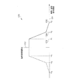
図8は、マルチパス環境用の信号例(例えば、A/D変換器への信号入力)の正規化された確率密度関数(PDF)を有する図表800を示している。 FIG. 8 shows a diagram 800 having a normalized probability density function (PDF) of an example signal for a multipath environment (eg, signal input to an A / D converter).
x軸805に沿って、信号値が示されている。y軸806に沿って、確率が示されている。図表800は、チャネルなし(曲線804)、チャネルが1つ(曲線803)、チャネルが2つ(曲線802)、およびチャネルが3つ(曲線801)のマルチパス環境におけるアップリンク伝送信号の実数値の確率分布関数を示している。
Signal values are shown along the
以下では、一実施形態に従って、アップリンク信号に適応される量子化ステップを選択するための一般的な規則について説明する。 In the following, the general rules for selecting the quantization step adapted to the uplink signal according to one embodiment will be described.
アップリンク量子化方法(移動体端末301内におけるD/A量子化、および基地局305内におけるA/D量子化)を選択するために従う一般的な規則は、様々なLTEパラメータ設定用の信号分布を考慮することによって得られうる。例えば、キャリア数は、周波数領域内において6リソースブロック(resource block;RB)から最大で110リソースブロックまで変更されうる。一実施形態では、「リソースブロック」(RB)という用語は、3GPP LTEに準拠して定義されるリソースブロックをいう(例えば、Release8)。極端な場合(周波数領域内のリソースブロックが6および110)および中間的な場合(周波数領域内のリソースブロックが50)において生じる信号分布は、図9に示されている。
The general rule to follow for selecting the uplink quantization method (D / A quantization in the
図9は、LTE構造内におけるアップリンク信号およびダウンリンク信号の正規化された確率密度関数(PDF)を有する3つの図表907,908,909を示している。 FIG. 9 shows three diagrams 907, 908, 909 having normalized probability density functions (PDFs) of uplink and downlink signals in the LTE structure.
各x軸905に沿って、信号値が示されている。各y軸906に沿って、確率が示されている。これら3つの図表907,908,909は、アップリンク伝送信号の虚数値(曲線901)、アップリンク伝送信号の実数値(曲線902)、ダウンリンク伝送信号の虚数値(曲線903)、およびダウンリンク伝送信号の実数値(曲線904)の確率分布関数を示している。第1の図表907は、6リソースブロックに対するこれらの信号を示し、第2の図表908は、50リソースブロックに対するこれらの信号を示し、第3の図表909は、110リソースブロックに対するこれらの信号を示している。
A signal value is shown along each
図9では、信号電力は、使用されるキャリアの平均電力が「1」となり、使用されていないキャリアの平均電力が「0」となるように選択されている。これは、例えば、なぜ右側のPDFの振幅値範囲が、 In FIG. 9, the signal power is selected such that the average power of the used carrier is “1” and the average power of the unused carrier is “0”. This is because, for example, the amplitude value range of the right PDF is
よりも大きいのかを説明している。 Explains what is bigger than.
図9によると、アップリンク(UL)(実数部および虚数部の両方)の場合、信号分布は、 According to FIG. 9, for the uplink (UL) (both real and imaginary parts), the signal distribution is
の数値範囲にわたって一定分布に近いことが観察される。ここで、「max」は、グラフ上方において識別される最大近似が観察される振幅である(6RBに対して約+/−0.3、50RBに対して約+/−1、110RBに対して約+/−1.3等)。 It is observed that the distribution is close to a constant distribution over a numerical range. Here, “max” is the amplitude at which the maximum approximation identified above the graph is observed (about +/− 0.3 for 6 RB, about +/− 1 for 50 RB, for 110 RB About +/- 1.3).
従って、一実施形態では、アップリンク量子化は以下に従って行われる:
1)関連するD/A変換器および/またはA/D変換器の、(移動体端末の伝送連鎖内のD/A、および基地局の受信連鎖内のA/Dに対する)量子化ステップは、
Thus, in one embodiment, uplink quantization is performed according to the following:
1) The quantization steps (for D / A in the mobile terminal's transmission chain and A / D in the base station's reception chain) of the associated D / A converter and / or A / D converter are:
の振幅領域内においてほぼ線形となるように選択される。 Are selected so as to be substantially linear within the amplitude region.
2) 2)
の数値範囲外では、量子化ステップサイズは、ステップからステップへ(入力値の増加する絶対値の方向に)、顕著に増加するように選択される。 Outside of this numerical range, the quantization step size is chosen to increase significantly from step to step (in the direction of absolute value where the input value increases).
3)一実施形態では、ほぼゼロの入力に対して非ゼロの量子化振幅をもたらす(これは、正値範囲および負値範囲での量子化ステップの非対称性に起因する:「N=2M」(「M」は整数)の量子化ステップの場合、典型的には「N/2−1」の負量子化振幅、「N/2」の正量子化振幅、およびゼロ振幅がある)量子化最適化手順とは対照的に、ほぼゼロの入力の量子化振幅は、ゼロになるように選択される。このことは、この場合では直流オフセットが問題となりうるため、同期化関数において有利となりうる。 3) In one embodiment, results in a quantized amplitude of the non-zero for near-zero input (which is due to the asymmetry of the quantization step in the positive range and negative value range: "N = 2 M ”(Where“ M ”is an integer) typically has a negative quantization amplitude of“ N / 2−1 ”, a positive quantization amplitude of“ N / 2 ”, and a zero amplitude) In contrast to the optimization optimization procedure, the near zero input quantization amplitude is chosen to be zero. This can be advantageous in the synchronization function, since in this case DC offset can be a problem.
上記1)〜3)に係る量子化の実施例は、図10に示されている。 An example of quantization according to the above 1) to 3) is shown in FIG.
図10は、一実施形態に係る量子化器の伝達関数を有する図表1000を示している。図表1000では、入力値(x軸1001に沿って示されている)と出力値(y軸1002に沿って示されている)との関係が示されている。中間的な数値範囲(ゼロ周辺)に対しては、楕円1003で示されているように準線形量子化が用いられる。中間的な数値範囲内の絶対値よりも大きい絶対値を有する信号値では、量子化ステップサイズは、矢印1004で示されているように、信号値の絶対値の増加に伴って増加する。
FIG. 10 shows a diagram 1000 having a transfer function of a quantizer according to one embodiment. The
図10に示されている可変範囲は、周波数領域内の50リソースブロックを用いたLTEパラメータ化に基づいており、用いられた各OFDMキャリアの平均電力は「1」である。別のパラメータ設定に従って、用いられたOFDMキャリアの数が、(例えば、図9のように6リソースブロックおよび110リソースブロックに)変更されるとき、対応する入力/出力値は、図10に示されている量子化器の入力/出力値を、この平均電力差分数の平方根に対応する因数で乗算することによって取得されうる。言い換えると、平均入力電力レベルが変化する場合、量子化ステップ設定間における単純線形関係が用いられうる。 The variable range shown in FIG. 10 is based on LTE parameterization using 50 resource blocks in the frequency domain, and the average power of each OFDM carrier used is “1”. When the number of used OFDM carriers is changed (eg, to 6 resource blocks and 110 resource blocks as in FIG. 9) according to different parameter settings, the corresponding input / output values are shown in FIG. Can be obtained by multiplying the input / output values of the quantizers by a factor corresponding to the square root of this average power difference number. In other words, if the average input power level changes, a simple linear relationship between the quantization step settings can be used.
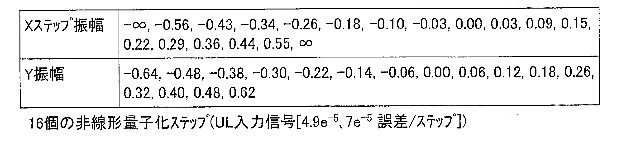
一実施形態では、例えば、表1〜6に与えられた量子化ステップが適用される。これらの値は、50リソースブロックに基づいて、LTEアップリンク信号用の電力レベルに適応される。他の電力レベルでは、表1〜6に与えられた振幅は、例えば、 In one embodiment, for example, the quantization steps given in Tables 1-6 are applied. These values are adapted to the power level for LTE uplink signals based on 50 resource blocks. At other power levels, the amplitudes given in Tables 1-6 are, for example,
で線形にスケーリングされる。 Is scaled linearly.
表7には、図10に示されている量子化の性能が、線形量子化の平均量子化誤差と比較して示されている。 Table 7 shows the performance of the quantization shown in FIG. 10 compared to the average quantization error of linear quantization.
なお、図10に係る量子化と線形量子化との性能差は、量子化ステップ数と共に生じることに留意されたい。より多い有効ビット数(または量子化ステップ数)にとっては、この差によって、変換器の精度を1ビット低下させることができるので、この差は電力消費を顕著に低減させるために用いられうる。この性質の理由は、i)少ない量子化ステップ数に対しては、頻繁に生じる振幅に対して(両方の量子化法に対して)全てのステップが用いられ、他の全ては飽和領域内にあるので、両方の量子化法間における差は小さい、およびii)より多い量子化ステップ数に対しては、これらはより低い頻度で生じる振幅でより効率的に用いられるので、性能差が生じる、という点に見られる。 It should be noted that the performance difference between the quantization and the linear quantization according to FIG. 10 occurs with the number of quantization steps. For larger effective bits (or quantization steps), this difference can reduce the accuracy of the converter by 1 bit, so this difference can be used to significantly reduce power consumption. The reasons for this property are: i) For a small number of quantization steps, all steps are used (for both quantization methods) for frequently occurring amplitudes, all others within the saturation region. As such, the difference between both quantization methods is small, and ii) for higher number of quantization steps, there is a performance difference because they are used more efficiently with less frequently occurring amplitudes, It is seen in the point.
一実施形態では、UL信号に適応される(最適な)量子化ステップを見つけるために、以下の方法が用いられる。これは、反復処理に基づいており、一般的な任意のタイプの信号分配に適用可能である。 In one embodiment, the following method is used to find the (optimal) quantization step adapted to the UL signal. This is based on iterative processing and is applicable to any general type of signal distribution.
この処理によると、
1)ほぼゼロの信号の量子化振幅は、ゼロになるように保証される(これは、例えば、典型的には相関器に基づく時間同期には重要であり、非常に小さい入力信号のための非ゼロ量子化振幅によって導入される直流オフセットによって、同期化の精度および効率の劣化が生じうる)、および、
2)量子化ステップサイズは、前述の制約下において、所定の信号分配に(最適に)適応される。
According to this process,
1) The quantized amplitude of a nearly zero signal is guaranteed to be zero (this is important for time synchronization, eg typically based on correlators, for very small input signals DC offset introduced by non-zero quantizing amplitude can cause degradation of synchronization accuracy and efficiency), and
2) The quantization step size is (optimally) adapted to a given signal distribution under the aforementioned constraints.
図11は、一実施形態に係るフローチャート1100を示している。フローチャート1100は、一実施形態に係る量子化ステップを設定する方法を示している。
FIG. 11 shows a
1101では、一部の初期化が行われる:
・目標とする量子化ステップ数「N=2M」(Mは整数)を設定し、
・初期の量子化誤差「eq」が、量子化ステップ毎に達成されるように設定し(最良の推測)、
・正値範囲および負値範囲のための初期入力変数をxpos=0およびxneg=0に設定し、また、対応する量子化出力をypos=0,yneg=0に設定し、
・(対応するPDF「p(x)」(約ゼロ)と共に)考慮されるように、最小および最大入力振幅を設定する:xmax,xmin。
At 1101, some initialization is performed:
Set the target number of quantization steps “N = 2 M ” (M is an integer)
Set the initial quantization error “e q ” to be achieved at each quantization step (best guess),
Set initial input variables for positive and negative ranges to x pos = 0 and x neg = 0, and corresponding quantized outputs to y pos = 0, y neg = 0,
Set the minimum and maximum input amplitudes as considered (with corresponding PDF “p (x)” (approximately zero)): x max , x min .
1102では、ypos=0として、平均量子化誤差が、 In 1102, assuming y pos = 0, the average quantization error is
を満たすまで、xposを増加させる。 Increase x pos until
1103では、ypos=2xpos−yposと設定し、平均量子化誤差 1103 sets y pos = 2x pos −y pos, and average quantization error
が得られるまで、またはxpos>xmaxとなるまで、xposを増加させる。 X pos is increased until x pos > x max is obtained.
1103は、xpos<xmaxである間、繰り返される。 1103 is repeated as long as x pos <x max .
1104では、目標とする量子化ステップ数が達せられたかどうか、および、全ての量子化ステップに対して同一の平均量子化誤差が達成されたかどうか、が検査される。 At 1104, it is checked whether the target number of quantization steps has been reached and whether the same average quantization error has been achieved for all quantization steps.
これら2つの目的が達成されていない場合、eqは更新され、処理は1102に戻る。そうでない場合、処理は1108において終了する。 If these two objectives are not achieved, eq is updated and processing returns to 1102. Otherwise, the process ends at 1108.
1105では、yneg=0として、平均量子化誤差が、 In 1105, assuming y neg = 0, the average quantization error is
を満たすまで、xnegを減少させる。 X neg is decreased until
1006では、yneg=2xneg−ynegと設定し、平均量子化誤差 In 1006, y neg = 2x neg −y neg is set and the average quantization error is set.
が得られるまで、またはxneg<xminとなるまで、xnegを減少させる。 X neg is reduced until x is obtained or until x neg <x min .
1106は、xpos>xminである間、繰り返される。 1106 is repeated as long as x pos > x min .
1107では、目標とする量子化ステップ数が達せられたかどうか、および、全ての量子化ステップに対して同一の平均量子化誤差が達成されたかどうか、が検査される。 At 1107, it is checked whether the target number of quantization steps has been reached and whether the same average quantization error has been achieved for all quantization steps.
これら2つの目的が達成されていない場合、eqは更新され、処理は1105に戻る。そうでない場合、処理は1108において終了する。 If these two objectives are not achieved, eq is updated and processing returns to 1105. Otherwise, the process ends at 1108.
一実施例として、信号の正規化された確率密度関数が、シミュレーションによってどのように近似されうるのかについて以下に説明する。これは、3GPP LTEに準拠する物理アップリンク共有チャネル(Physical Uplink Shared Channel;PUSC)に対して行われる。このチャネルは、有用なデータを搬送し、また最高感度の変調方式(QPSKから64QAMまで)を有している。他のチャネルは、例えば、物理アップリンク制御チャネル(Physical Uplink Control Channel;PUCCH)および物理ランダムアクセスチャネル(Physical Random Access Channel;PRACH)である。 As an example, the following describes how the normalized probability density function of a signal can be approximated by simulation. This is performed for a physical uplink shared channel (PUSC) compliant with 3GPP LTE. This channel carries useful data and has the most sensitive modulation scheme (QPSK to 64QAM). Other channels are, for example, a physical uplink control channel (PUCCH) and a physical random access channel (PRACH).
シミュレーションには以下のパラメータが考慮されうる:
リソースブロック毎のサブキャリア数:値は、
The following parameters can be considered for the simulation:
Number of subcarriers per resource block:
に固定される。 Fixed to.
アップリンクスロット内のSC−FDMAシンボル数は、 The number of SC-FDMA symbols in the uplink slot is
である。この値は、変調器出力の分配に影響を及ぼすことはなく、以下に説明する解析には考慮されない。 It is. This value does not affect the distribution of the modulator output and is not considered in the analysis described below.
配置タイプは、QAM4、QAM16、QAM64である。一実施形態では、量子化の最適化は、特定の実施によって支持される最も高い配置タイプに対して行われる。なぜなら、これが最も高い要求につながるからである。 The arrangement types are QAM4, QAM16, and QAM64. In one embodiment, quantization optimization is performed on the highest placement type supported by a particular implementation. This is because it leads to the highest demands.
結果は、アップリンク通信のための複素数値時間領域信号の実数値および虚数値の両方に適用する。実信号および虚信号の変換に対しては、それぞれ、異なるA/D変換器またはD/A変換器が用いられると仮定される。従って、低い変換周波数速度を達成することができる(「アナログI/Q法」として知られている)。あるいは、バンド幅が最小バンド幅の二倍(またはそれ以上)であるデジタルベースバンド信号が、1つの単一A/DまたはD/A変換器で十分であるように生成される(「デジタルI/Q法」)。結果は、後者の方法にも直接的に適用することができる。 The results apply to both real and imaginary values of complex valued time domain signals for uplink communications. It is assumed that different A / D converters or D / A converters are used for real signal and imaginary signal conversion, respectively. Thus, low conversion frequency rates can be achieved (known as “analog I / Q method”). Alternatively, a digital baseband signal whose bandwidth is twice (or more) the minimum bandwidth is generated such that one single A / D or D / A converter is sufficient (“Digital I / Q method "). The results can be applied directly to the latter method.
なお、シミュレーション結果は、考慮されるリソースブロックのいかなる周波数シフトにも無関係であることに留意されたい。周波数シフトは、信号の分配に影響を及ぼさない時間領域において、単純な相変化に変換する。これは、異なる複数のユーザがアップリンク構造に同時に信号を伝送している場合、各ユーザは、様々な信号が干渉しないように、自身の対応するリソースブロックに周波数シフトを適用していると考えられることを意味する。この場合、量子化の最適化は、各ハンド設定内において独立して行われうる。 Note that the simulation results are independent of any frequency shift of the considered resource block. The frequency shift converts to a simple phase change in the time domain that does not affect the distribution of the signal. This is because when different users are simultaneously transmitting signals to the uplink structure, each user applies a frequency shift to their corresponding resource block so that various signals do not interfere. Means that In this case, quantization optimization can be performed independently within each hand setting.
以下に説明するシミュレーション結果は、信号の実数部分および虚数部分に適用可能な信号分配の近似(すなわち信号の確率分布)を与えるものである。すなわち、両分配は同一である。さらに、これらの結果は、正の振幅値に対してのみ与えられる。これは、負の振幅に対して全く同一の分配を観察することができるからである:f(x)=f(−x)。ここで、f(x)は正規化された確率密度関数である。以下に与えられた全ての値は、使用された各キャリアの電力が「1」と等しく、キャリアの総数が4096(これは、本実施例ではFFT/IFFTサイズでもある)と等しいと仮定している。これは、リソースブロック数が多いほど、信号の全電力がより高くなることを意味している。全てのシミュレーションは、データシンボルのみに基づいており、プリアンブルおよび他のラーニングフィールドは考慮されない。この理由は、SNR要件が、データシンボル内においてより高くなることが予想されるという事実にある。 The simulation results described below provide an approximation of signal distribution (ie, the probability distribution of the signal) applicable to the real and imaginary parts of the signal. That is, both distributions are the same. Furthermore, these results are given only for positive amplitude values. This is because the exact same distribution can be observed for negative amplitudes: f (x) = f (−x). Here, f (x) is a normalized probability density function. All the values given below assume that the power of each carrier used is equal to “1” and the total number of carriers is equal to 4096 (which is also the FFT / IFFT size in this example). Yes. This means that the greater the number of resource blocks, the higher the total power of the signal. All simulations are based on data symbols only and the preamble and other learning fields are not considered. The reason for this is the fact that the SNR requirement is expected to be higher in the data symbols.
信号分布(すなわち信号値の確率分布)は、図12に示されているように、確率密度関数によって近似されうる。 The signal distribution (ie, the probability distribution of signal values) can be approximated by a probability density function, as shown in FIG.
図12は、一実施形態に係る関数グラフ1200を示している。
FIG. 12 shows a
x軸1201に沿って、信号値が示されている。y軸1202に沿って、近似に従った確率が示されている。本実施例では、近似は、軸対称の区分線形関数である。ゼロから第1の値1203(A1で示されている)までの第1の区間では、確率分布関数(正規化された確率密度関数とも称される)は一定である。第1の値1203から第2の値1204(A2で示されている)までの第2の区間では、確率分布関数は線形に減少している。第2の値1203から第3の値1205(A3で示されている)までの第3の区間においても同様である。本実施例では、確率分布関数は、第3の区間よりも第2の区間において、より急速に減少する。
A signal value is shown along the
シミュレーションから得られた、異なる変調方式およびリソースブロック数に対する、関数グラフ1200のエッジ値A1,A2,およびA3が、表8に示されている。表8では、これらの変調技術に対して、直交位相シフトキーイング(Quadrature Phase Shift Keying;QPSK)および直交振幅変調(Quadrature Amplitude Modulation;QAM)が用いられている。
Table 8 shows the edge values A 1 , A 2 , and A 3 of the
無線信号の正規化された確率密度関数(例えば、図12に示されているもの)の近似を、例えば表8のパラメータを用いて生成する処理を、図13に示す。 FIG. 13 shows a process for generating an approximation of the normalized probability density function (for example, shown in FIG. 12) of the radio signal using, for example, the parameters in Table 8.
図13は、一実施形態に係るフローチャートを示している。 FIG. 13 shows a flowchart according to an embodiment.
1301では、選択された配置タイプ(本実施例では、QPSK配置)内のポイントが無作為に選択され、キャリアグリッド上にマッピングされる。使用されていないキャリアは0に設定される。 At 1301, points within the selected placement type (QPSK placement in this example) are randomly selected and mapped onto the carrier grid. Unused carriers are set to zero.
1302では、例えば3GPPに準拠するプリコーディングが行われる。このプリコーディングタイプは、典型的には、高速フーリエ変換(Fast Fourier Transform;FFT)によって実施される。図13に示されている式は、そのような3GPPに準拠するプリコーディングに対応している。 In 1302, for example, precoding conforming to 3GPP is performed. This precoding type is typically implemented by Fast Fourier Transform (FFT). The equation shown in FIG. 13 corresponds to such 3GPP-compliant precoding.
なお、図13に示されているフローは、LTEアップリンクの場合に関するフローであることに留意されたい。ダウンリンクの場合は、1302が省略される。 Note that the flow shown in FIG. 13 is for the LTE uplink. In the case of the downlink, 1302 is omitted.
1303では、SC−FDMAベースバンド信号生成(アップリンクの場合)、またはOFDM(A)信号生成(ダウンリンクの場合)が、例えば3GPPに準拠して行われる。このプリコーディングタイプは、典型的には、逆高速フーリエ変換(Inverse Fast Fourier Transform;IFFT)によって実施されることに留意されたい。 In 1303, SC-FDMA baseband signal generation (in the case of uplink) or OFDM (A) signal generation (in the case of downlink) is performed based on, for example, 3GPP. Note that this precoding type is typically implemented by an Inverse Fast Fourier Transform (IFFT).
図13に示されている式は、そのような3GPPに準拠する信号生成に対応している。 The equation shown in FIG. 13 corresponds to such 3GPP-compliant signal generation.
1304では、複素数値SC−FDMA信号またはOFDM(A)信号の、実数値および虚数値の統計が、それぞれ更新される。正規化された確率密度関数は、実数値および虚数値がどの程度の頻度で生じているのかを評価することによって得られうる。この目的のために、十分に小さい区間が定義されうる。これらの区間では、実数値および虚数値が一定であると仮定される。これらの区間のそれぞれでは、発生回数が数えられた後、真に正規化された確率密度関数を近似することができるように、適切に正規化される。 At 1304, real-valued and imaginary-value statistics of the complex-valued SC-FDMA signal or OFDM (A) signal are updated respectively. A normalized probability density function can be obtained by evaluating how often real and imaginary values occur. For this purpose, a sufficiently small interval can be defined. In these intervals, the real and imaginary values are assumed to be constant. In each of these intervals, after the number of occurrences is counted, it is appropriately normalized so that a true normalized probability density function can be approximated.
上記処理は、統計が十分に正確となる(すなわち、結果の変化が反復後に十分に小さくなる)まで、要求されるたびに、(1301から再度開始して)反復される。 The above process is repeated as needed (starting again at 1301) until the statistics are sufficiently accurate (ie the change in results is sufficiently small after the iterations).
特定の正規化された確率密度関数を有する信号用の最適な量子化を生成するとき、最適な解決手段(これにより、より多い量子化ステップ数にとって、平均二乗誤差性能が数デシベル向上されうる)と線形量子化と間の差異が、典型的にはステップサイズのわずか一部分であることが観察されうる。従って、一実施形態では、量子化(擬似線形量子化と称される)は、第1の振幅値範囲内において用いられる。この第1の振幅値範囲の量子化ステップは、この範囲における対応する線形量子化の量子化ステップとは、多くとも当該線形量子化の量子化ステップサイズのサイズだけ異なる。 Optimal solution when generating optimal quantization for signals with a particular normalized probability density function (this can improve the mean square error performance by several decibels for a larger number of quantization steps) It can be observed that the difference between and linear quantization is typically only a fraction of the step size. Thus, in one embodiment, quantization (referred to as quasi-linear quantization) is used within the first amplitude value range. The quantization step of this first amplitude value range differs from the corresponding linear quantization quantization step in this range by at most the size of the quantization step size of the linear quantization.
一実施形態では、そのような擬似線形量子化が用いられる信号値範囲を設定するために、エッジ値A1,A2,およびA3が用いられる。例えば、擬似線形量子化は、−A1からA1の信号値範囲内において用いられる、すなわち、その絶対値が最大でもA1である信号値に用いられる。正規化された確率密度関数の「エッジ近似」に対して必要とされる精度に関しては、エッジ振幅A1,A2,およびA3が、一実施形態では、振幅誤差が量子化ステップ幅(各振幅値において、すなわち、絶対値A1,A2,またはA3をそれぞれ有する)よりも小さくなるような精度で実施される。 In one embodiment, in order to set such a pseudo-linear quantized signal value range used, edge values A 1, A 2, and A 3 is used. For example, quasi-linear quantization is used within a signal value range of −A 1 to A 1 , that is, a signal value whose absolute value is at most A 1 . With respect to the accuracy required for the “edge approximation” of the normalized probability density function, the edge amplitudes A 1 , A 2 , and A 3 are, in one embodiment, the amplitude error is the quantization step width (each in the amplitude value, that is, carried out at an absolute value a 1, a 2 or with a 3, respectively) becomes smaller such precision than,.
本発明について、具体的な実施形態を参照しながら図示および説明した。しかし当業者であれば、特許請求の範囲によって定義される本発明の精神および範囲から逸脱することなく、形式および詳細に様々な変更を加えることができることを理解するであろう。従って、本発明の範囲は特許請求の範囲によって示されており、特許請求の範囲に相当する部分の意味および範囲内での全ての変更が包含されるものと意図されている。 The invention has been illustrated and described with reference to specific embodiments. However, one of ordinary skill in the art appreciates that various changes can be made in form and detail without departing from the spirit and scope of the invention as defined by the claims. Accordingly, the scope of the present invention is defined by the terms of the claims, and is intended to include any modifications within the meaning and scope of the parts corresponding to the claims.
Claims (25)
2つの量子化ステップ間における量子化ステップ幅が、同数の量子化ステップを有する線形量子化とは、多くとも上記同数の量子化ステップを有する線形量子化のステップ幅だけ異なる、複数の量子化ステップを有する第1の量子化に従って、第1の数値範囲内にある信号値を量子化する工程と、
2つの量子化ステップ間における量子化ステップ幅が、上記第1の量子化の2つの量子化ステップ間における量子化ステップ幅よりも大きい、複数の量子化ステップを有する第2の量子化に従って、第2の数値範囲内にある信号値を量子化する工程とを含む、方法。 A method for quantizing a signal value of a signal received or transmitted via a wireless interface, comprising:
A plurality of quantization steps in which the quantization step width between two quantization steps is different from the linear quantization having the same number of quantization steps by at least the linear quantization step width having the same number of quantization steps. Quantizing a signal value within a first numerical range according to a first quantization having:
According to a second quantization having a plurality of quantization steps, the quantization step width between the two quantization steps being larger than the quantization step width between the two quantization steps of the first quantization. Quantizing a signal value within a numerical range of two.
2つの量子化ステップ間における量子化ステップ幅が、同数の量子化ステップを有する線形量子化とは、多くとも当該同数の量子化ステップを有する線形量子化のステップ幅だけ異なる、複数の量子化ステップを有する第1の量子化に従って、第1の数値範囲内にある信号値を量子化するように構成された、第1の量子化回路と、
2つの量子化ステップ間における量子化ステップ幅が、上記第1の量子化の2つの量子化ステップ間における量子化ステップ幅よりも大きい、複数の量子化ステップを有する第2の量子化に従って、第2の数値範囲内にある信号値を量子化する、第2の量子化回路とを含む、量子化器。 A quantizer for quantizing a signal value of a signal received or transmitted via a wireless interface,
A plurality of quantization steps in which the quantization step width between two quantization steps differs from the linear quantization having the same number of quantization steps by at most the linear quantization step width having the same number of quantization steps. A first quantization circuit configured to quantize a signal value within a first numerical range according to a first quantization having:
According to a second quantization having a plurality of quantization steps, the quantization step width between the two quantization steps being larger than the quantization step width between the two quantization steps of the first quantization. And a second quantizing circuit for quantizing a signal value within a numerical range of 2.
第1の量子化に従って、上記通信装置に伝送される信号を量子化する工程と、
第2の量子化に従って、上記通信装置から受信された信号を量子化する工程とを含み、
上記第1の量子化は、上記第2の量子化が量子化ステップを含まない信号値において、量子化ステップを含んでおり、
上記第2の量子化は、上記第1の量子化が量子化ステップを含まない信号値において、量子化ステップを含んでいる、方法。 A method of quantizing a signal received from a communication device or a signal transmitted to the communication device,
Quantizing a signal transmitted to the communication device according to a first quantization;
Quantizing a signal received from the communication device according to a second quantization,
The first quantization includes a quantization step in a signal value where the second quantization does not include a quantization step;
The method wherein the second quantization includes a quantization step at a signal value where the first quantization does not include a quantization step.
第1の量子化に従って、上記通信装置に伝送される信号を量子化するように構成されている第1の量子化回路と、
第2の量子化に従って、上記通信装置から受信された信号を量子化するように構成されている第2の量子化回路とを備え、
上記第1の量子化は、上記第2の量子化が量子化ステップを含まない信号値において、量子化ステップを含んでおり、
上記第2の量子化は、上記第1の量子化が量子化ステップを含まない信号値において、量子化ステップを含んでいる、量子化器。 A quantizer that quantizes a signal received from a communication device or a signal transmitted to the communication device,
A first quantization circuit configured to quantize a signal transmitted to the communication device according to a first quantization;
A second quantization circuit configured to quantize a signal received from the communication device according to a second quantization,
The first quantization includes a quantization step in a signal value where the second quantization does not include a quantization step;
The quantizer in which the second quantization includes a quantization step in a signal value in which the first quantization does not include a quantization step.
上記通信装置に伝送される信号の信号値の確率分布に適応されている第1の量子化に従って、上記通信装置に伝送される信号を量子化する工程と、
上記通信装置から受信された信号の信号値の確率分布に適応されている第2の量子化に従って、上記通信装置から受信された信号を量子化する工程とを含む、方法。 A method of quantizing a signal received from a communication device or a signal transmitted to the communication device,
Quantizing the signal transmitted to the communication device according to a first quantization adapted to a probability distribution of signal values of the signal transmitted to the communication device;
Quantizing the signal received from the communication device according to a second quantization adapted to a probability distribution of signal values of the signal received from the communication device.
Applications Claiming Priority (2)
| Application Number | Priority Date | Filing Date | Title |
|---|---|---|---|
| US12/171,696 US7688245B2 (en) | 2008-07-11 | 2008-07-11 | Method for quantizing of signal values and quantizer |
| US12/171,696 | 2008-07-11 |
Publications (2)
| Publication Number | Publication Date |
|---|---|
| JP2010022002A true JP2010022002A (en) | 2010-01-28 |
| JP4860727B2 JP4860727B2 (en) | 2012-01-25 |
Family
ID=41412966
Family Applications (1)
| Application Number | Title | Priority Date | Filing Date |
|---|---|---|---|
| JP2009164615A Expired - Fee Related JP4860727B2 (en) | 2008-07-11 | 2009-07-13 | Method and quantizer for quantizing signal values |
Country Status (3)
| Country | Link |
|---|---|
| US (1) | US7688245B2 (en) |
| JP (1) | JP4860727B2 (en) |
| DE (1) | DE102009023578A1 (en) |
Cited By (3)
| Publication number | Priority date | Publication date | Assignee | Title |
|---|---|---|---|---|
| KR20140111461A (en) * | 2013-03-11 | 2014-09-19 | 삼성전자주식회사 | Method and apparatus for timing acquisition in code division multiple access system |
| JP2015070545A (en) * | 2013-09-30 | 2015-04-13 | Kddi株式会社 | Transmitter and receiver for base band signal |
| US9800264B2 (en) | 2015-03-09 | 2017-10-24 | Panasonic Corporation | Transmission device and quantization method |
Families Citing this family (10)
| Publication number | Priority date | Publication date | Assignee | Title |
|---|---|---|---|---|
| US9247547B2 (en) * | 2009-10-15 | 2016-01-26 | Qualcomm Incorporated | Downlink and uplink resource element mapping for carrier extension |
| US8542605B2 (en) * | 2009-10-15 | 2013-09-24 | Qualcomm Incorporated | System and method for allocating resources in an extended bandwidth wireless network |
| CN101764817A (en) * | 2009-12-24 | 2010-06-30 | 中兴通讯股份有限公司 | Wireless access data terminal and system and method for realizing data communication |
| GB2478000B (en) * | 2010-02-23 | 2016-01-06 | Qualcomm Technologies Int Ltd | Improved quantization method for ofdm |
| GB2499671B (en) * | 2012-02-27 | 2014-04-09 | Broadcom Corp | Apparatus and method for communication |
| DE102014116909B4 (en) * | 2014-11-19 | 2016-07-28 | Infineon Technologies Ag | A receiver, transmitter, method for retrieving an additional data value from a signal and method for transmitting a data value and an additional data value in a signal |
| US10459079B2 (en) | 2015-10-09 | 2019-10-29 | Zte Corporation | Method for transmitting a quantized value in a communication system |
| DE102016102005B4 (en) * | 2016-02-04 | 2018-08-02 | Rheinisch-Westfälische Technische Hochschule Aachen (RWTH) | Circuit arrangement and method for generating a high-frequency, analog transmission signal |
| US10467433B2 (en) | 2017-03-17 | 2019-11-05 | Mediasift Limited | Event processing system |
| DE102021100771A1 (en) | 2021-01-15 | 2022-07-21 | Universität Stuttgart, Körperschaft Des Öffentlichen Rechts | Mixed signal circuitry and method for efficient pulse shaping of digital signals |
Citations (4)
| Publication number | Priority date | Publication date | Assignee | Title |
|---|---|---|---|---|
| WO1989012359A1 (en) * | 1988-06-08 | 1989-12-14 | Fujitsu Limited | Signal processor |
| JPH04313928A (en) * | 1991-03-25 | 1992-11-05 | Mitsubishi Electric Corp | Voice signal processing circuit |
| JPH06244887A (en) * | 1992-10-26 | 1994-09-02 | Philips Electron Nv | Digital radio equipment |
| JPH09319868A (en) * | 1996-05-31 | 1997-12-12 | Pentel Kk | A/d conversion reference voltage setting circuit |
Family Cites Families (43)
| Publication number | Priority date | Publication date | Assignee | Title |
|---|---|---|---|---|
| US3305855A (en) * | 1962-11-08 | 1967-02-21 | Nippon Electric Co | Encoder and a decoder with nonlinear quantization |
| US4791483A (en) * | 1987-11-20 | 1988-12-13 | The Grass Valley Group, Inc. | Adaptive differential pulse code modulation video encoder |
| JPH01256278A (en) * | 1988-04-06 | 1989-10-12 | Canon Inc | Prediction coding system |
| JP2754741B2 (en) * | 1989-06-09 | 1998-05-20 | キヤノン株式会社 | Encoding device |
| US5053771A (en) * | 1990-07-16 | 1991-10-01 | Eastman Kodak Company | Adaptive dual range analog to digital converter |
| JP2790240B2 (en) | 1994-06-07 | 1998-08-27 | 日本ビクター株式会社 | Orthogonal frequency division multiplexed signal transmitting / receiving device |
| JPH0846660A (en) | 1994-07-29 | 1996-02-16 | Sony Corp | Digital signal modulation circuit |
| JP3086636B2 (en) | 1995-08-31 | 2000-09-11 | 三洋電機株式会社 | Analog-digital conversion circuit |
| GB9821385D0 (en) | 1998-10-01 | 1998-11-25 | British Broadcasting Corp | Improvements relating to measuring channel state from a received signal and discriminating digital values from a received signal,suitable for use in cofdm |
| SE513113C2 (en) | 1998-11-11 | 2000-07-10 | Ericsson Telefon Ab L M | Method and apparatus for maximizing the ratio of signal to quantization noise in AD conversion of a multicarrier signal |
| FR2789501B1 (en) * | 1999-02-09 | 2001-04-13 | St Microelectronics Sa | METHOD AND DEVICE FOR REDUCING THE CONSUMPTION OF A MICROCONTROLLER |
| EP1041790B1 (en) | 1999-03-30 | 2004-11-24 | Nec Corporation | Symbol timing recovery for OFDM demodulator |
| JP4109404B2 (en) * | 2000-04-26 | 2008-07-02 | 松下電器産業株式会社 | Encoding apparatus and encoding method |
| JP3976168B2 (en) | 2001-09-06 | 2007-09-12 | 株式会社エヌ・ティ・ティ・ドコモ | Transmitter and receiver |
| JP4078581B2 (en) | 2002-02-04 | 2008-04-23 | ソニー株式会社 | Image processing apparatus and method, recording medium, and program |
| US7133473B1 (en) * | 2002-02-15 | 2006-11-07 | Marvell International Ltd. | Divisionless baseband equalization in symbol modulated communications |
| KR20040027153A (en) | 2002-09-27 | 2004-04-01 | 엘지전자 주식회사 | Transmitting and receiving system of orthogonal frequency division multiplexing type using companding |
| US7274750B1 (en) * | 2002-09-27 | 2007-09-25 | 3Com Corporation | Gain and phase imbalance compensation for OFDM systems |
| KR20040032683A (en) * | 2002-10-10 | 2004-04-17 | 엘지전자 주식회사 | Fast fourier transform apparatus for wireless lan system |
| EP1445958A1 (en) * | 2003-02-05 | 2004-08-11 | STMicroelectronics S.r.l. | Quantization method and system, for instance for video MPEG applications, and computer program product therefor |
| ATE336107T1 (en) | 2003-04-30 | 2006-09-15 | Freescale Semiconductor Inc | METHOD AND DEVICE FOR DIGITAL-ANALOG/ANALOG-DIGITAL CONVERSION WITH REDUCED ENERGY CONSUMPTION |
| US6873280B2 (en) * | 2003-06-12 | 2005-03-29 | Northrop Grumman Corporation | Conversion employing delta-sigma modulation |
| CA2433139C (en) * | 2003-06-23 | 2012-03-27 | Wavesat Wireless Inc. | Synchronizing method and apparatus |
| US7280612B2 (en) * | 2003-07-25 | 2007-10-09 | Zarbana Digital Fund Llc | Digital branch calibrator for an RF transmitter |
| US7257175B2 (en) * | 2003-08-20 | 2007-08-14 | Afa Technologies, Inc. | Method and apparatus for periodic signal detection in OFDM/DMT systems |
| KR100510549B1 (en) * | 2003-09-26 | 2005-08-26 | 삼성전자주식회사 | Channel state measurement apparatus providing for detecting and suppressing of co-channel interference in digital video broadcasting receiver and method therefor |
| JP3933626B2 (en) | 2003-12-18 | 2007-06-20 | 株式会社東芝 | OFDM modulator |
| JP4486387B2 (en) | 2004-03-19 | 2010-06-23 | パナソニック株式会社 | Error compensation apparatus and error compensation method |
| US7539253B2 (en) * | 2004-09-10 | 2009-05-26 | Intel Corporation | Interpolation in channel state feedback |
| KR100929084B1 (en) * | 2004-12-03 | 2009-11-30 | 삼성전자주식회사 | Dithering device and method in communication system |
| JP2006186427A (en) * | 2004-12-24 | 2006-07-13 | Toshiba Corp | Wireless communication method and device |
| KR100605109B1 (en) * | 2005-01-18 | 2006-07-28 | 삼성전자주식회사 | Method and Apparatus for Improving SNR with Oversampling in an OFDM Systems |
| KR100938792B1 (en) | 2005-03-10 | 2010-01-27 | 퀄컴 인코포레이티드 | A method to track analog gain step magnitudes online during operation of wireless mobile devices |
| KR100754622B1 (en) * | 2005-03-25 | 2007-09-05 | 삼성전자주식회사 | Apparatus and method for transmitting a signal in a communication system |
| US7233633B2 (en) * | 2005-04-04 | 2007-06-19 | Motorola, Inc. | Channel estimation using linearly constrained filter coefficients |
| US7257171B2 (en) | 2005-04-04 | 2007-08-14 | Motorola, Inc. | Method and apparatus for reference symbol aided channel estimation |
| CN101248608B (en) | 2005-08-24 | 2012-03-14 | 松下电器产业株式会社 | Mimo-ofdm transmission device and mimo-ofdm transmission method |
| US7529531B2 (en) | 2005-11-09 | 2009-05-05 | Qualcomm, Incorporated | Apparatus and methods for estimating a sleep clock frequency |
| WO2007094832A2 (en) | 2005-11-17 | 2007-08-23 | The University Of Connecticut | Recursive and trellis-based feedback reduction for mimo-ofdm with rate-limited feedback |
| US20070211813A1 (en) | 2006-03-10 | 2007-09-13 | Shilpa Talwar | MIMO precoding in the presence of co-channel interference |
| US7756222B2 (en) * | 2006-05-04 | 2010-07-13 | Integrated System Solution Corporation | Adaptive quantization method and apparatus for an OFDM receiver |
| US8654912B2 (en) * | 2006-05-05 | 2014-02-18 | Samsung Electronics Co., Ltd. | MIMO transmitter with pooled adaptive digital filtering |
| US7295144B1 (en) * | 2006-05-22 | 2007-11-13 | Redpine Signals, Inc. | Quantizer responsive to noise level for a wireless communications system |
-
2008
- 2008-07-11 US US12/171,696 patent/US7688245B2/en not_active Expired - Fee Related
-
2009
- 2009-06-02 DE DE102009023578A patent/DE102009023578A1/en not_active Withdrawn
- 2009-07-13 JP JP2009164615A patent/JP4860727B2/en not_active Expired - Fee Related
Patent Citations (4)
| Publication number | Priority date | Publication date | Assignee | Title |
|---|---|---|---|---|
| WO1989012359A1 (en) * | 1988-06-08 | 1989-12-14 | Fujitsu Limited | Signal processor |
| JPH04313928A (en) * | 1991-03-25 | 1992-11-05 | Mitsubishi Electric Corp | Voice signal processing circuit |
| JPH06244887A (en) * | 1992-10-26 | 1994-09-02 | Philips Electron Nv | Digital radio equipment |
| JPH09319868A (en) * | 1996-05-31 | 1997-12-12 | Pentel Kk | A/d conversion reference voltage setting circuit |
Cited By (4)
| Publication number | Priority date | Publication date | Assignee | Title |
|---|---|---|---|---|
| KR20140111461A (en) * | 2013-03-11 | 2014-09-19 | 삼성전자주식회사 | Method and apparatus for timing acquisition in code division multiple access system |
| KR102028011B1 (en) * | 2013-03-11 | 2019-10-02 | 삼성전자주식회사 | Method and apparatus for timing acquisition in code division multiple access system |
| JP2015070545A (en) * | 2013-09-30 | 2015-04-13 | Kddi株式会社 | Transmitter and receiver for base band signal |
| US9800264B2 (en) | 2015-03-09 | 2017-10-24 | Panasonic Corporation | Transmission device and quantization method |
Also Published As
| Publication number | Publication date |
|---|---|
| US7688245B2 (en) | 2010-03-30 |
| JP4860727B2 (en) | 2012-01-25 |
| US20100007543A1 (en) | 2010-01-14 |
| DE102009023578A1 (en) | 2010-01-14 |
Similar Documents
| Publication | Publication Date | Title |
|---|---|---|
| JP4860727B2 (en) | Method and quantizer for quantizing signal values | |
| RU2420878C2 (en) | Cqi reporting for mimo transmission in wireless communication system | |
| US10411935B2 (en) | System and method for DFT-S-OFDM PAPR reduction | |
| EP3567915B1 (en) | Wireless communication method, device and system | |
| KR100849749B1 (en) | Transmitter and transmission method | |
| CN109462566B9 (en) | Information transmission method and device | |
| US9935757B2 (en) | Channel quality reporting for full-duplex radio | |
| CN111345077B (en) | Maximum power reduction for uplink bandwidth portion of wireless network | |
| CN111901263B (en) | Wireless signal compensation method, numerical value determination method and device, equipment and medium | |
| WO2008054099A1 (en) | Method for transmitting and receiving channel quality information in multi carrier wireless system | |
| US7609609B2 (en) | Apparatus and method for processing digital signal in an OFDMA wireless communication system | |
| US20100153049A1 (en) | Apparatus, system, and method for calculating a non-linearity metric | |
| US9386569B2 (en) | Processing information blocks for wireless transmission | |
| JP2009246587A (en) | Communication device for receiving ofdm signal, ofdm radio communication system and ofdm receiving method | |
| KR102097713B1 (en) | Apparatus and method for channel quality information feedback in wireless communication system using fequency qudrature amplitude modulation | |
| US11251913B2 (en) | Methods and apparatuses for controlling a bandwidth used for processing a baseband transmit signal, receiver for a wireless communication system, and method for a receiver | |
| WO2019190469A1 (en) | Transmitters and methods for operating the same | |
| KR102486149B1 (en) | Apparatus and method for peak to average power reduction in wireless communication system | |
| KR20180122917A (en) | Method and apparatus for transmitting and receiving a signal for low peak-to-average power ratio signal in wireless communications systems | |
| WO2010139095A1 (en) | Method of and base station for reducing peak - to - average power ratio for a multicarrier transmission | |
| KR101420523B1 (en) | Method for cancelling inter-carrier interference in distributed antenna system | |
| US20230042213A1 (en) | Methods and systems for optimizing computation of log-likelihood ratio (llr) for decoding modulated symbols | |
| US20230327936A1 (en) | Phase noise suppression method and related apparatus | |
| CN110431890B (en) | Method and device used in user and base station of wireless communication | |
| WO2023193883A1 (en) | Apparatuses and methods for transmission quality aware uplink power control |
Legal Events
| Date | Code | Title | Description |
|---|---|---|---|
| A977 | Report on retrieval |
Free format text: JAPANESE INTERMEDIATE CODE: A971007 Effective date: 20110920 |
|
| TRDD | Decision of grant or rejection written | ||
| A01 | Written decision to grant a patent or to grant a registration (utility model) |
Free format text: JAPANESE INTERMEDIATE CODE: A01 Effective date: 20111004 |
|
| A01 | Written decision to grant a patent or to grant a registration (utility model) |
Free format text: JAPANESE INTERMEDIATE CODE: A01 |
|
| A61 | First payment of annual fees (during grant procedure) |
Free format text: JAPANESE INTERMEDIATE CODE: A61 Effective date: 20111102 |
|
| R150 | Certificate of patent or registration of utility model |
Free format text: JAPANESE INTERMEDIATE CODE: R150 |
|
| FPAY | Renewal fee payment (event date is renewal date of database) |
Free format text: PAYMENT UNTIL: 20141111 Year of fee payment: 3 |
|
| S111 | Request for change of ownership or part of ownership |
Free format text: JAPANESE INTERMEDIATE CODE: R313113 |
|
| FPAY | Renewal fee payment (event date is renewal date of database) |
Free format text: PAYMENT UNTIL: 20141111 Year of fee payment: 3 |
|
| R350 | Written notification of registration of transfer |
Free format text: JAPANESE INTERMEDIATE CODE: R350 |
|
| LAPS | Cancellation because of no payment of annual fees |