JP2010020447A - Article conveyance device for vending machine - Google Patents

Article conveyance device for vending machine Download PDF

Info

Publication number
JP2010020447A
JP2010020447A JP2008178829A JP2008178829A JP2010020447A JP 2010020447 A JP2010020447 A JP 2010020447A JP 2008178829 A JP2008178829 A JP 2008178829A JP 2008178829 A JP2008178829 A JP 2008178829A JP 2010020447 A JP2010020447 A JP 2010020447A
Authority
JP
Japan
Prior art keywords
product
support member
vending machine
auxiliary plate
holding auxiliary
Prior art date
Legal status (The legal status is an assumption and is not a legal conclusion. Google has not performed a legal analysis and makes no representation as to the accuracy of the status listed.)
Granted
Application number
JP2008178829A
Other languages
Japanese (ja)
Other versions
JP5277759B2 (en
Inventor
Takashi Higashida
隆司 東田
Yoshiyuki Nakamura
善幸 中村
Ken Suwabe
憲 諏訪部
Norihiko Yonehara
典彦 米原
Current Assignee (The listed assignees may be inaccurate. Google has not performed a legal analysis and makes no representation or warranty as to the accuracy of the list.)
Panasonic Corp
Original Assignee
Panasonic Corp
Priority date (The priority date is an assumption and is not a legal conclusion. Google has not performed a legal analysis and makes no representation as to the accuracy of the date listed.)
Filing date
Publication date
Application filed by Panasonic Corp filed Critical Panasonic Corp
Priority to JP2008178829A priority Critical patent/JP5277759B2/en
Publication of JP2010020447A publication Critical patent/JP2010020447A/en
Application granted granted Critical
Publication of JP5277759B2 publication Critical patent/JP5277759B2/en
Expired - Fee Related legal-status Critical Current
Anticipated expiration legal-status Critical

Links

Images

Abstract

<P>PROBLEM TO BE SOLVED: To prevent the article carrying-out device of a vending machine from not normally operating due to deformation of the second beverage article from the bottom, which is caused when the second article from the bottom is once held by the next article support member and an article passageway board, in the article carrying-out device of the vending machine. <P>SOLUTION: The article carrying-out device 17 mounted on the article storage rack 3 of the vending machine 1 is enabled to normally sell the second article from the bottom even when the held article is deformed when once holding the second article from the bottom by the next article support member 20 and the article passageway board 18 by mounting an article holding auxiliary board 34 on the top end of the next article holding member 20, and holding the article on an article holding surface without having any gap. <P>COPYRIGHT: (C)2010,JPO&INPIT

Description

本発明は、自動販売機に内蔵されて飲料商品を収容する商品収容棚内に取り付けられている商品搬出装置に関するものである。   The present invention relates to a product carry-out device that is built into a vending machine and is mounted in a product storage shelf that stores beverage products.

従来の自動販売機用の商品収容棚内に取り付けられている商品搬出装置として、下記特許文献1に開示されているものが知られている。   As a merchandise carry-out device attached in a merchandise storage shelf for a conventional vending machine, one disclosed in Patent Document 1 below is known.

缶商品や近年ではPETボトル商品などのさまざまな飲料商品を扱う自動販売機は、次のような構造となっているのが一般的である。   Vending machines that handle various beverage products such as can products and recently PET bottle products generally have the following structure.

以下、図面を参照しながら特許文献1に記載の自動販売機の商品収容棚内に取り付けられている商品搬出装置について説明する。   Hereinafter, a product carry-out device attached to a product storage shelf of a vending machine described in Patent Document 1 will be described with reference to the drawings.

図10は従来の自動販売機の商品搬出装置の要部断面図である。図において、自動販売機内には、投入口傾斜板などで構成される商品投入口部と、蛇行上に上下方向に伸びた商品通路100、可動側板および商品搬出装置101とで構成される商品収容棚が複数収納されている。   FIG. 10 is a cross-sectional view of a main part of a conventional product carry-out device of a vending machine. In the figure, a vending machine accommodates a product input port composed of a product inlet inclined plate and the like, a product passage 100 extending in a vertical direction on a meander, a movable side plate, and a product carry-out device 101. Multiple shelves are stored.

自動販売機で販売される飲料商品102は、この商品収容棚に一旦収容され、その後販売される構造となっており、収容から販売までの流れとしては、商品投入口部に水平状態で投入された飲料商品102は投入口傾斜板から水平状態を保持しながら商品通路100へ収容され、収容された商品は商品通路100の下端部に取り付けられた商品搬出装置の主商品支持部材107の上に水平状態で積み上げられていき販売待機状態となる。   The beverage product 102 sold by the vending machine is structured to be temporarily stored in the product storage shelf and then sold, and as a flow from storage to sales, it is input in a horizontal state into the product inlet. The beverage product 102 is accommodated in the product passage 100 while maintaining a horizontal state from the charging port inclined plate, and the accommodated product is placed on the main product support member 107 of the product delivery device attached to the lower end of the product passage 100. It will be piled up in a horizontal state and will be in a standby state for sale.

その後、販売信号に応じて下から2本目の飲料商品102を次期商品支持部材103と商品通路板104で一旦保持し、その間に最下部商品を商品搬出装置101の主商品支持部材107の回動動作により払い出すことで購入者に飲料商品102を提供する構造となっている。   Thereafter, the second beverage product 102 from the bottom is temporarily held by the next product support member 103 and the product passage plate 104 in accordance with the sales signal, and the lowermost product is rotated between the main product support members 107 of the product carry-out device 101 in the meantime. The beverage product 102 is provided to the purchaser by paying out by operation.

その際、下から2本目の飲料商品102には、上方に積み上げられた飲料商品の荷重がかかるため変形を生じる。   At that time, the second beverage product 102 from the bottom is deformed due to the load of the beverage product stacked upward.

自動販売機で販売される飲料商品は、缶商品やPETボトル商品やびん商品といった容器種類の違い、中身飲料の容量の違いからさまざまな種類の飲料商品が販売されており、また、一方で原材料の削減を目的とした缶商品やPETボトル商品の容器の薄肉化が進んでいる。   Beverage products sold at vending machines are sold in various types due to differences in container types such as can products, PET bottle products, and bottle products, and differences in the capacity of content beverages. Thinning of containers for can products and PET bottle products for the purpose of reducing the amount of water is progressing.

そのため、自動販売機では前述したような多種多様な飲料商品が販売可能であることが望まれている。   Therefore, it is desired that vending machines can sell a wide variety of beverage products as described above.

前述のような多種多様な飲料商品、特に薄肉化の進んだ脆弱容器を商品収容棚で正常に販売するためには、販売信号に応じて下から2本目の飲料商品を、次期商品支持部材103と商品通路板104で一旦保持する際に生じる下から2本目の飲料商品102の変形によっても、異常を発生することなく正常に販売することのできる商品搬出装置が必要とされている。   In order to normally sell a wide variety of beverage products as described above, in particular, fragile containers whose thickness has been reduced, on the product storage shelf, the second beverage product from the bottom is sent to the next product support member 103 according to the sales signal. Therefore, there is a need for a product carry-out device that can be normally sold without causing an abnormality even when the second beverage product 102 from the bottom that is deformed once held by the product passage plate 104 is deformed.

図10に示す従来の商品搬出装置101においては、商品搬出装置101のフレーム105に商品保持補助板106が取り付けられており、次期商品支持部材103が商品通路100の壁面側から中央側に向かって突出した時に、商品保持補助板106を次期商品支持部材103の商品保持面を覆うように配置させ、商品保持面の有する隙間を小さくする構造となっている。
特開2003−196726号公報
In the conventional product carry-out device 101 shown in FIG. 10, a product holding auxiliary plate 106 is attached to the frame 105 of the product carry-out device 101, and the next product support member 103 moves from the wall surface side to the center side of the product passage 100. When protruding, the product holding auxiliary plate 106 is arranged so as to cover the product holding surface of the next product support member 103, and the gap of the product holding surface is reduced.
JP 2003-196726 A

上記特許文献1に開示されている商品搬出装置101は、商品搬出装置101のフレーム105に商品保持補助板106が取り付けられており、次期商品支持部材103が商品通路100の壁面側から中央側に向かって突出した時に、商品保持補助板106を次期商品支持部材103の商品保持面を覆うように配置させ、商品保持面の有する隙間を小さくする構造となっている。   In the product carry-out device 101 disclosed in Patent Document 1, a product holding auxiliary plate 106 is attached to the frame 105 of the product carry-out device 101, and the next product support member 103 moves from the wall surface side to the center side of the product passage 100. The product holding auxiliary plate 106 is disposed so as to cover the product holding surface of the next product support member 103 when protruding toward the front, so that the gap of the product holding surface is reduced.

しかしながら、上記従来の構造の商品搬出装置101では、商品保持補助板106が販売時に次期商品支持部材103が商品通路100の壁面側から中央側に向かって突出する動作を妨げないような大きさにする必要があるため、次期商品支持部材103の先端にある商品保持面を完全に覆うことができない。   However, in the product carry-out device 101 having the above-described conventional structure, the product holding auxiliary plate 106 is sized so as not to hinder the operation in which the next product support member 103 protrudes from the wall surface side of the product passage 100 toward the center side at the time of sale. Therefore, the product holding surface at the tip of the next product support member 103 cannot be completely covered.

また、次期商品支持部材103の商品保持面は、商品搬出装置101に収納される際に、他の部品との干渉をさけるため、本体部と爪部によって構成されている。   Further, the product holding surface of the next product support member 103 is constituted by a main body portion and a claw portion in order to avoid interference with other components when stored in the product carry-out device 101.

そのため、次期商品支持部材103の先端に形成される商品保持面は均一な面で形成することができず、次期商品支持部材103の本体部と爪によって構成されるため、商品保持面に空間を有することが避けられない構造となっている。   For this reason, the product holding surface formed at the tip of the next product support member 103 cannot be formed as a uniform surface, and is constituted by the main body portion and the claws of the next product support member 103. It has an inevitable structure.

以上のことから、前記従来の自動販売機の商品搬出装置101では、次期商品支持部材103の最大突出時に商品保持面の有する隙間を完全に埋めることができずに、次期商品支持部材103の先端部と商品保持補助板間106に隙間が残ってしまう。   For the above reasons, in the conventional product vending machine 101 of the vending machine, the gap of the product holding surface cannot be completely filled when the next product support member 103 is fully projected, and the tip of the next product support member 103 is A gap remains between the part and the product holding auxiliary plate 106.

そのため、販売信号に応じて下から2本目の飲料商品を、次期商品支持部材103と商品通路板104で一旦保持する際に生じる下から2本目の飲料商品102の変形によって、飲料商品が次期商品支持部材103の本体部と爪部によって形成される商品保持面に存在する隙間に入り込み、次期商品支持部材103が動作不能になるといった販売異常が発生する可能性がある。   Therefore, in response to the sales signal, the second beverage product from the bottom is temporarily held by the next product support member 103 and the product passage plate 104, and the beverage product becomes the next product due to the deformation of the second beverage product 102 from the bottom. There is a possibility that a sales abnormality may occur in which the next product support member 103 becomes inoperable by entering a gap existing on the product holding surface formed by the main body portion and the claw portion of the support member 103.

本発明は、上記従来の課題を解決するもので、販売信号に応じて下から2本目の飲料商品を、次期商品支持部材103と商品通路板104で一旦保持する際に生じる下から2本目の飲料商品の変形が発生しても、正常に販売を行うことのできる自動販売機の商品搬出装置を提供することを目的とする。   The present invention solves the above-described conventional problems, and the second beverage product from the bottom that occurs when the second beverage product from the bottom is temporarily held by the next product support member 103 and the product passage plate 104 in response to the sales signal. An object of the present invention is to provide a vending machine product carry-out device that can perform normal sales even when a beverage product is deformed.

上記従来の課題を解決するために、本発明の自動販売機の商品搬出装置は、自動販売機の商品収容棚の商品通路に取り付けられ、商品通路の壁面側から中央側に向かって突出・後退して最下流側に位置する商品を保持する主商品支持部材と、前記主商品支持部材の上流側に位置して、揺動軸を中心として揺動し、商品通路中央側へ突出・後退することによって下流側から二番目の商品を保持する次期商品支持部材を備えた商品搬出装置において、次期商品支持部材に商品保持補助板を取り付けたものである。   In order to solve the above-mentioned conventional problems, the product unloading device of the vending machine according to the present invention is attached to the product passage of the product storage shelf of the vending machine and protrudes / retreats from the wall surface side to the center side of the product passage. A main product support member for holding the product located on the most downstream side, and located on the upstream side of the main product support member, swinging about the swing shaft, and projecting / retreating to the center of the product passage Thus, in the product carry-out device including the next product support member that holds the second product from the downstream side, the product support auxiliary plate is attached to the next product support member.

これによって、次期商品支持部材の商品保持面を隙間なく構成することができ、販売信号に応じて下から2本目の飲料商品を、次期商品支持部材と商品通路板で一旦保持する際に生じる下から2本目の飲料商品の変形を防止することができる。   As a result, the product holding surface of the next product support member can be configured without gaps, and the second beverage product from the bottom according to the sales signal is generated when the second product support member is temporarily held by the next product support member and the product passage plate. Therefore, deformation of the second beverage product can be prevented.

本発明の自動販売機の商品搬出装置は、次期商品支持部材に商品保持補助板を取り付けたことにより、商品保持面を隙間のない面によって構成することで、販売信号に応じて下から2本目の飲料商品を、次期商品支持部材と商品通路板で一旦保持する際に生じる下から2本目の飲料商品の変形を防止できるので、多種多様な飲料商品を正常に販売を行うことのできる自動販売機の商品搬出装置が提供できる。   The product unloading device of the vending machine according to the present invention is configured such that the product holding auxiliary plate is attached to the next product support member, so that the product holding surface is constituted by a surface without a gap, so that the second product from the bottom according to the sales signal. Can prevent the deformation of the second beverage product from the bottom that occurs when the beverage product is temporarily held by the next product support member and the product passage plate, so that a wide variety of beverage products can be sold normally A product unloading device can be provided.

請求項1に記載の発明は、自動販売機の商品収容棚の商品通路に取り付けられ、商品通路の壁面側から中央側に向かって突出・後退して最下流側に位置する商品を保持する主商品支持部材と、前記主商品支持部材の上流側に位置して、揺動軸を中心として揺動し、商品通路中央側へ突出・後退することによって下流側から二番目の商品を保持する次期商品支持部材を備えた商品搬出装置において、次期商品支持部材に商品保持補助板を設けたものであり、商品保持面の隙間を減らすことができ、販売信号に応じて下から2本目の飲料商品を、次期商品支持部材と商品通路板で一旦保持する際に生じる下から2本目の飲料商品の変形を防止でき、多種多様な飲料商品を正常に販売を行うことができる。   The invention according to claim 1 is attached to the product passage of the product storage shelf of the vending machine, and holds the product located on the most downstream side by projecting and retreating from the wall surface side to the center side of the product passage. The next stage, which is located upstream of the main product support member, swings about the swing shaft, and holds the second product from the downstream side by protruding and retracting toward the center of the product passage. In the product carry-out device provided with the product support member, the next product support member is provided with a product holding auxiliary plate, the gap of the product holding surface can be reduced, and the second beverage product from the bottom according to the sales signal Can be prevented from deforming the second beverage product from the bottom, which is generated when the product is temporarily held by the next product support member and the product passage plate, and a wide variety of beverage products can be normally sold.

請求項2に記載の発明は、請求項1に記載の発明において、次期商品支持部材の先端部に商品保持補助板を回動自在に取り付けたものであり、簡素な構造で商品保持面の隙間を減らすことができる。   The invention according to claim 2 is the invention according to claim 1, wherein a product holding auxiliary plate is rotatably attached to the tip of the next product support member, and the clearance between the product holding surfaces with a simple structure. Can be reduced.

請求項3に記載の発明は、請求項2に記載の発明において、次期商品支持部材の先端部に商品保持補助板回転ピンを取り付け、商品保持補助板回転ピンを軸に回転自在に商品保持補助板を設けたものであり、簡素な構造で商品保持補助板の回動を支持しながら、商品保持面の隙間を減らすことができる。   The invention according to claim 3 is the invention according to claim 2, wherein a product holding auxiliary plate rotation pin is attached to the tip of the next product support member, and the product holding auxiliary is rotatable about the product holding auxiliary plate rotation pin. A plate is provided, and the clearance between the product holding surfaces can be reduced while supporting the rotation of the product holding auxiliary plate with a simple structure.

請求項4に記載の発明は、請求項2または3に記載の発明において、商品保持補助板の回転域において次期商品支持部材に干渉させることで回転規制を設けたものであり、簡素な構造で商品保持補助板の回動を規制することができる。   The invention according to claim 4 is the invention according to claim 2 or 3, wherein the rotation restriction is provided by interfering with the next product support member in the rotation region of the product holding auxiliary plate, and the structure is simple. The rotation of the product holding auxiliary plate can be restricted.

請求項5に記載の発明は、請求項1から4のいずれか一項に記載の発明において、商品保持補助板を次期商品支持部材の後退動作時の回転方向に付勢させる付勢手段を備えたものであり、次期商品支持部材を商品通路中央側へ突出・後退する際の動作に連動して、確実に商品保持補助板を動作させることができる。   According to a fifth aspect of the present invention, in the invention according to any one of the first to fourth aspects, the product holding auxiliary plate is provided with a biasing means for biasing the product holding auxiliary plate in the rotational direction during the backward movement of the next product support member. Therefore, the product holding auxiliary plate can be reliably operated in conjunction with the operation when the next product support member protrudes / retreats toward the center of the product passage.

請求項6に記載の発明は、請求項5に記載の発明において、付勢手段が次期商品支持部材の商品通路側に突出しない構造としたものであり、商品搬出時に商品通路を阻害することがなく、確実に多種多様な飲料商品を正常に販売を行うことができる。   The invention according to claim 6 is the invention according to claim 5, wherein the urging means does not protrude to the product passage side of the next product support member, and the product passage is obstructed when the product is carried out. In addition, it is possible to reliably sell a wide variety of beverage products.

請求項7に記載の発明は、請求項1から6のいずれか一項に記載の発明において、次期商品支持部材が販売待機状態で商品搬出装置のフレーム内に存在する時に、商品保持補助板が前記フレームの表面に沿うように収納するものであり、商品搬出時に商品保持補助板が商品通路を阻害することがなく、確実に多種多様な飲料商品を正常に販売を行うことができる。   The invention according to claim 7 is the invention according to any one of claims 1 to 6, wherein when the next product support member is present in the frame of the product carry-out device in a sales standby state, the product holding auxiliary plate is The product is stored so as to be along the surface of the frame, and the product holding auxiliary plate does not obstruct the product passage when the product is carried out, so that a wide variety of beverage products can be sold normally without fail.

請求項8に記載の発明は、請求項7に記載の発明において、フレームに段差部を設け、前記段差部に商品保持補助板を収納するものであり、商品保持補助板の収納性を向上しながら、商品搬出時に商品保持補助板が商品通路を阻害することがなく、確実に多種多様な飲料商品を正常に販売を行うことができる。   The invention according to claim 8 is the invention according to claim 7, wherein the frame is provided with a stepped portion, and the product holding auxiliary plate is stored in the stepped portion. However, the product holding auxiliary plate does not obstruct the product passage when the product is unloaded, and a wide variety of beverage products can be reliably sold.

以下、本発明の実施の形態について、図面を参照しながら説明する。なお、この実施の形態によってこの発明が限定されるものではない。   Hereinafter, embodiments of the present invention will be described with reference to the drawings. The present invention is not limited to the embodiments.

(実施の形態1)
本発明の実施の形態1にかかる自動販売機の商品搬出装置について、図面を参照しながら詳細に説明する。なお、以下の説明では、特に断りのない限り上下方向、幅方向、奥行き方向等の位置関係については、自動販売機やこれに組み込まれる商品収納棚の通常の設置状態を基準として説明する。
(Embodiment 1)
A commodity carry-out device for a vending machine according to a first embodiment of the present invention will be described in detail with reference to the drawings. In the following description, the positional relationship in the vertical direction, the width direction, the depth direction, and the like will be described based on the normal installation state of the vending machine and the product storage shelf incorporated therein unless otherwise specified.

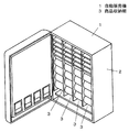
図1は本発明の実施の形態1における自動販売機を示す斜視図である。自動販売機1は、図1に示すように断熱性を有する箱状の本体部2の内部に複数の商品収納棚3や、図示しない商品搬出装置、制御装置等を内蔵した構成とされている。   FIG. 1 is a perspective view showing a vending machine according to Embodiment 1 of the present invention. As shown in FIG. 1, the vending machine 1 has a configuration in which a plurality of product storage shelves 3, a product take-out device (not shown), a control device, and the like are built in a box-shaped main body 2 having heat insulation properties. .

図2は、本発明の実施の形態1における自動販売機の商品収容棚の斜視図である。商品収容棚3は、図2に示すように、対向して配置され商品収容棚3を構成する各部品を取り付けるための複数の穴を設けた側壁4と、商品収容棚3の前面に上下方向に複数配置された投入口傾斜板5と、上下方向に連続して配置された商品通路6を形成するセグメント7と、搬出口部8によって構成されている。   FIG. 2 is a perspective view of a commodity storage shelf of the vending machine according to Embodiment 1 of the present invention. As shown in FIG. 2, the product storage shelf 3 is arranged in a vertical direction on the front surface of the product storage shelf 3 and a side wall 4 provided with a plurality of holes for mounting the parts arranged to face each other and constituting the product storage shelf 3. A plurality of input port inclined plates 5, a segment 7 forming a product passage 6 continuously arranged in the vertical direction, and a carry-out port portion 8.

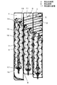
図3は、本発明の実施の形態1における自動販売機の商品収容棚の側面図である。   FIG. 3 is a side view of the commodity storage shelf of the vending machine according to Embodiment 1 of the present invention.

図3に示すように、商品収容棚3は飲料商品9が収容される複数の商品通路6によって構成されている。   As shown in FIG. 3, the product storage shelf 3 includes a plurality of product passages 6 in which beverage products 9 are stored.

商品投入口部11は飲料商品9が自重で転がるまたは滑ることのできる程度の傾斜を有し、側壁4に設けた異形溝12内を動作可能に係合された投入口傾斜板5と、投入口傾斜板5上を幅方向に移動可能に係合された投入口幅規制部材13と、投入口傾斜板5と商品通路6の境界部に設けた投入口規制部材14によって構成される。   The product inlet 11 has an inclination enough to allow the beverage product 9 to roll or slide under its own weight, and the inlet inclined plate 5 operatively engaged in the deformed groove 12 provided in the side wall 4, It is constituted by an input port width restricting member 13 engaged so as to be movable in the width direction on the mouth inclined plate 5 and an input port restricting member 14 provided at a boundary portion between the input port inclined plate 5 and the product passage 6.

図3に示す商品通路6は、上下方向に複数蛇行するように配置された円弧状のセグメント7と、飲料商品9が商品通路6内を落下する際の落下速度の抑制と姿勢制御の機能を有したフラッパ15、収容される飲料商品9の全長にあわせて商品通路幅を変えるために、投入口幅規制部材13を設定するのと連動するように投入口幅規制部材13に係合された可動側板16、商品通路6の最下部には商品搬出装置17と商品搬出装置17に対向するように配置された通路規制板18で構成された搬出口部8によって構成されている。   The merchandise path 6 shown in FIG. 3 has a circular arc segment 7 arranged so as to meander in the up and down direction, and functions of suppressing the dropping speed and controlling the posture when the beverage merchandise 9 falls in the merchandise path 6. In order to change the width of the product passage in accordance with the length of the flapper 15 and the beverage product 9 to be accommodated, the flapper 15 is engaged with the input port width restricting member 13 so as to be interlocked with the setting of the input port width restricting member 13. At the lowermost part of the movable side plate 16 and the product passage 6, a product outlet device 8 constituted by a product delivery device 17 and a passage restriction plate 18 disposed so as to face the product delivery device 17 is constituted.

ここで、飲料商品9が商品収容棚3に収容され販売されるまでの一連の流れについて説明する。   Here, a series of flows until the beverage product 9 is stored in the product storage shelf 3 and sold will be described.

図3に示すように、投入口傾斜板5の上端部から水平状態で投入された飲料商品9は、水平状態を保ちながら投入口傾斜板5上を転動し投入口傾斜板5の下端部に至る。投入口傾斜板5の下端部から投げ出された飲料商品9は、進行方向を変え商品通路6内を落下し始める。   As shown in FIG. 3, the beverage product 9 that is thrown in the horizontal state from the upper end portion of the charging port inclined plate 5 rolls on the charging port inclined plate 5 while maintaining the horizontal state, and the lower end portion of the charging port inclined plate 5. To. The beverage product 9 thrown out from the lower end portion of the charging port inclined plate 5 changes its traveling direction and starts to fall in the product passage 6.

投入口傾斜板5から商品通路6への移行の際に進行方向が大きく変わり飲料商品9は姿勢を崩しやすいため、投入口傾斜板5の下端部上方に投入口規制部材14が設けられている。   Since the direction of travel changes greatly during the transition from the input port inclined plate 5 to the product passage 6 and the beverage product 9 tends to lose its posture, the input port regulating member 14 is provided above the lower end of the input port inclined plate 5. .

この投入口規制部材14を介することで、投入口傾斜板5から商品通路6への移行の際に、飲料商品9は水平状態を保つことができる。   The beverage product 9 can be kept in a horizontal state during the transition from the input port inclined plate 5 to the product passage 6 through the input port regulating member 14.

商品通路6は前述したように、上下方向に複数蛇行するように配置された円弧状のセグメント7とフラッパ15によって構成されており、飲料商品9はセグメント7とフラッパ15によって落下速度を抑制すると同時に、姿勢制御されながら商品通路6内を蛇行上に水平状態を保ちながら落下していく。   As described above, the merchandise passage 6 is composed of the arc-shaped segment 7 and the flapper 15 arranged so as to meander in the vertical direction, and the beverage merchandise 9 simultaneously suppresses the falling speed by the segment 7 and the flapper 15. Then, while the attitude is controlled, the product passage 6 falls while maintaining a horizontal state in a meandering manner.

次に、飲料商品9は商品通路6を経て商品通路6の下部に設けられた搬出口部8に移行する。   Next, the beverage product 9 moves through the product passage 6 to the carry-out port 8 provided at the lower part of the product passage 6.

前述したように、搬出口8は商品搬出装置17と商品搬出装置17に対向するように配置された通路規制板18で構成されており、飲料商品9は商品搬出装置17のストッパーによって落下の終点を迎える。   As described above, the carry-out port 8 is composed of the product carry-out device 17 and the passage restriction plate 18 disposed so as to face the product carry-out device 17, and the beverage product 9 is dropped by the stopper of the product carry-out device 17. Greet.

この一連流れで飲料商品9は商品収容棚3内に次々に収容されていき、商品搬出装置17に積みあがった状態で販売待機状態となる。   With this series of flows, the beverage products 9 are successively stored in the product storage shelf 3 and are in a standby state after being stacked on the product carry-out device 17.

その後、販売信号に応じて商品搬出装置17は最下部の商品のみを下方に払い出すことで指定商品を消費者へと提供する。   Thereafter, in response to the sales signal, the product carry-out device 17 provides the designated product to the consumer by paying down only the bottom product.

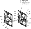
図4は、本発明の実施の形態1における自動販売機の商品搬出装置の正面図である。   FIG. 4 is a front view of the commodity carry-out device of the vending machine according to Embodiment 1 of the present invention.

図4に示すように、商品搬出装置17の枠上のフレーム18には、開口部19が設けられており、この開口部19に次期商品支持部材20および主商品支持部材21が、フレーム18および支持棒22a、支持棒22bによって軸支されたピン23c、ピン23dによって回転自在に設けられている。   As shown in FIG. 4, an opening 19 is provided in the frame 18 on the frame of the product carry-out device 17, and the next product support member 20 and the main product support member 21 are provided in the opening 19. It is rotatably provided by a pin 23c and a pin 23d that are pivotally supported by the support rod 22a and the support rod 22b.

ここで、主商品支持部材21は、商品通路内の最も下流にある商品を保持し、次期商品支持部材20は商品通路内の下から2番目の商品を保持する機能を有している。   Here, the main product support member 21 holds the product that is most downstream in the product passage, and the next product support member 20 has a function of holding the second product from the bottom in the product passage.

なお、主商品支持部材21には後退阻止部材24が配備されている。また、本実施の形態1の商品搬出装置17は、他にソレノイド25、連動部材26を持つ。   The main commodity support member 21 is provided with a retraction prevention member 24. In addition, the product carry-out device 17 of the first embodiment has a solenoid 25 and an interlocking member 26 in addition.

フレーム17aの開口部19には板状部27が設けられており、開口部19の下部の一部を閉鎖している。板状部27が設けられた位置は、フレーム17aの中心から向かって右側であり、商品搬出装置17を背中合わせに重ねた時に、相手側の商品搬出装置17に設けられた連動部材26に、動作を妨げる荷重がかかることのないように保護する位置に定められている。また、フレーム17aの正面側の開口部19の上部には、商品を後述する通路規制板側に寄せるための突起28が設けられている。   A plate-like portion 27 is provided in the opening 19 of the frame 17a, and a part of the lower portion of the opening 19 is closed. The position where the plate-like portion 27 is provided is on the right side from the center of the frame 17a, and when the product carry-out device 17 is stacked back to back, the interlocking member 26 provided in the counterpart product carry-out device 17 is operated. It is set at a position to protect it so as not to apply a load that prevents it. In addition, a projection 28 is provided at the upper part of the opening 19 on the front side of the frame 17a to bring the product to the side of the passage regulating plate described later.

図5は、本発明の実施の形態1における自動販売機の商品搬出装置の主商品支持部材の説明図である。   FIG. 5 is an explanatory diagram of a main product support member of the product carry-out device of the vending machine according to Embodiment 1 of the present invention.

図5に示すように、主商品支持部材21は略長方形の板状部材で、樹脂製の接合部材29が一体化されたものである。   As shown in FIG. 5, the main product support member 21 is a substantially rectangular plate-like member, and is formed by integrating a resin-made joining member 29.

主商品支持部材21の一辺側には、主商品支持部材21を回転自在に軸支するためのピン23dを挿通するための軸孔30aが設けられ、図5に示す樹脂製の接合部材29を係合するための切り欠き部21aおよび略L字型のL曲げ部21bがある。   A shaft hole 30a for inserting a pin 23d for pivotally supporting the main product support member 21 rotatably is provided on one side of the main product support member 21, and the resin-made joining member 29 shown in FIG. There are a notch 21a and a substantially L-shaped bent portion 21b for engagement.

一方、接合部材29は、板状部29aに軸孔30bが設けられており、さらに板状29aの平面に対して垂直な面にガイド溝31が設けられたものである。   On the other hand, the joining member 29 is provided with a shaft hole 30b in the plate-like portion 29a, and further provided with a guide groove 31 on a surface perpendicular to the plane of the plate-like 29a.

このガイド溝31は、図5に示すように長穴状になっており、後退阻止部材24の一端に挿通されているピン23eをガイドするものである。   The guide groove 31 has a long hole shape as shown in FIG. 5 and guides the pin 23 e inserted into one end of the retraction preventing member 24.

主商品支持部材21と接合部材29は、上記した主商品支持部材21の略L字型の曲げ部21bで嵌め合いによって一体化されており、主商品支持部材21の軸孔30aと接合部材の軸孔30bは、ピン23dによって挿通、回転自在に軸支されている。   The main product support member 21 and the joining member 29 are integrated by fitting at a substantially L-shaped bent portion 21b of the main product support member 21, and the shaft hole 30a of the main product support member 21 and the joining member are integrated. The shaft hole 30b is rotatably supported by the pin 23d.

図6は、本発明の実施の形態1における自動販売機の商品搬出装置の後退阻止部材の説明図である。   FIG. 6 is an explanatory view of the retraction prevention member of the commodity carry-out device of the vending machine in the first embodiment of the present invention.

図6に示すように、後退阻止部材24は平面部24aと両端がL状曲げされて、L曲げ部の上下端にピンを挿通するための軸孔を設けた帯状部24bと、平面部24aに設けられた切り起こし部24cと、平面部24aに設けられた切り起こし部24cの挿通穴に回転可能に取り付けられ、支持棒22aおよび支持棒22bに設けた異形溝内22cをガイドされながら移動するピン23fを挿通するための軸孔32aを有するロック部材32によって構成される。   As shown in FIG. 6, the receding prevention member 24 has a flat portion 24 a, a belt-like portion 24 b that is bent at both ends in an L shape, and a shaft hole for inserting a pin into the upper and lower ends of the L bent portion, and the flat portion 24 a. And is rotatably mounted in the insertion hole of the cut and raised portion 24c provided on the flat surface portion 24a, and moves while being guided in the deformed groove 22c provided on the support rod 22a and the support rod 22b. The lock member 32 has a shaft hole 32a for inserting the pin 23f to be inserted.

また、上述したようにロック部材32に挿通されたピン23fは、支持棒22aおよび支持棒22bに設けた異形溝内22cを移動可能に取り付けられており、同時に後述する連動部材26の下端部に係合され連動部材26に連動して動作する構造となっている。   Further, as described above, the pin 23f inserted into the lock member 32 is movably attached in the deformed groove 22c provided in the support rod 22a and the support rod 22b, and at the same time, on the lower end portion of the interlocking member 26 described later. It is structured to be engaged and operate in conjunction with the interlocking member 26.

連動部材26は板状の部材であり、フレーム17aに設けられたソレノイド25にプランジャー33を介して係合されており、フレーム17aに対して上下方向に往復動する。   The interlocking member 26 is a plate-like member, is engaged with a solenoid 25 provided on the frame 17a via a plunger 33, and reciprocates in the vertical direction with respect to the frame 17a.

また、連動部材26の中間部には次期商品支持部材20の突出を制御するピン23gが挿通軸支されており、ピン23gは支持棒22bに設けられた長穴およびフレーム17a内に設けられた長穴を往復動する。   Further, a pin 23g for controlling the protrusion of the next product support member 20 is inserted through the intermediate portion of the interlocking member 26, and the pin 23g is provided in a long hole provided in the support rod 22b and in the frame 17a. Reciprocates through the long hole.

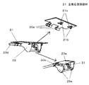
図7は、本発明の実施の形態1における自動販売機の商品搬出装置の次期商品支持部材の説明図である。   FIG. 7 is an explanatory diagram of the next product support member of the product carry-out device of the vending machine according to Embodiment 1 of the present invention.

図7に示すように、次期商品支持部材20は、高剛性のエンジニアリングプラスチックや金属のダイガストで成形されたものであり、本体部20aと複数の板状突起部20bと商品保持面20cとなる先端部および先端部に形成される爪部20dを持つ。   As shown in FIG. 7, the next product support member 20 is formed of high-rigidity engineering plastic or metal die cast, and is a tip that becomes a main body portion 20 a, a plurality of plate-like protrusions 20 b, and a product holding surface 20 c. And a claw portion 20d formed at the tip portion and the tip portion.

連動部材26の中間部に挿通軸支されたピン23gが連動部材26と伴って往復動する際に、ピン23gと板状突起部20bが当接することにより、次期商品支持部材20が回転、押し出される。   When the pin 23g inserted and supported at the intermediate part of the interlocking member 26 reciprocates together with the interlocking member 26, the next product support member 20 is rotated and pushed out by the contact of the pin 23g and the plate-like protrusion 20b. It is.

すなわち、次期商品支持部材20の板状突起部20bの形状によって、ピン23gが連動部材26と伴に往復動する際の次期商品支持部材20の商品通路側への突出量を決定することができる。   That is, the amount of protrusion of the next product support member 20 toward the product passage when the pin 23g reciprocates with the interlocking member 26 can be determined by the shape of the plate-like protrusion 20b of the next product support member 20. .

また、次期商品支持部材20の先端部には、次期商品支持部材20の長手方向に商品保持補助板回転ピン23hが挿通可能な軸孔が設けられており、商品保持補助板34が回転可能に商品保持補助板回転ピン23hによって次期商品支持部材20の先端部に回動自在に取り付けられている。   Further, a shaft hole through which the product holding auxiliary plate rotation pin 23h can be inserted in the longitudinal direction of the next product supporting member 20 is provided at the distal end portion of the next product supporting member 20, so that the product holding auxiliary plate 34 can be rotated. The product holding auxiliary plate rotation pin 23h is rotatably attached to the distal end portion of the next product support member 20.

商品保持補助板34は、図7に示すように、板状の部品で一端に商品保持補助板回転ピン23hが挿通可能な略円弧状部35が構成されており、前述したように商品保持補助板回転ピン23hによって次期商品支持部材20の先端部を軸とし、次期商品支持部材20の先端に設けた切り欠き部20e内に回転可能に取り付けられており、さらに、次期商品支持部材20の先端に設けた切り欠き部20e内で商品保持補助板回転ピン23hに挿通されたねじりコイルバネ36によって商品保持面20cに沿う方向、すなわち、次期商品支持部材20の後退動作時の回転方向に付勢されている。   As shown in FIG. 7, the product holding auxiliary plate 34 is a plate-shaped component having a substantially arcuate portion 35 into which the product holding auxiliary plate rotating pin 23 h can be inserted at one end. A plate rotation pin 23h is pivotally mounted in a notch 20e provided at the tip of the next product support member 20 with the tip of the next product support member 20 as an axis, and further the tip of the next product support member 20 The torsion coil spring 36 inserted through the product holding auxiliary plate rotation pin 23h in the notch 20e provided in the product is biased in the direction along the product holding surface 20c, that is, in the rotation direction when the next product support member 20 is retracted. ing.

ここで、ねじりコイルバネ36のアームの一端は、商品保持補助板34の裏面に取り付けられ、他端側は次期商品支持部材20の表面側、すなわち、商品通路側に取り付けられているが、次期商品支持部材20のねじりコイルバネ36のアームの取り付け部に凹部20fを設けて、表面側にねじりコイルバネ36のアームが突出しない構造となっている。   Here, one end of the arm of the torsion coil spring 36 is attached to the back surface of the product holding auxiliary plate 34, and the other end is attached to the front side of the next product support member 20, that is, the product passage side. A recess 20f is provided in the mounting portion of the arm of the torsion coil spring 36 of the support member 20 so that the arm of the torsion coil spring 36 does not protrude on the surface side.

図8は、本発明の実施の形態1における自動販売機の商品搬出装置の動作説明図である。   FIG. 8 is a diagram for explaining the operation of the commodity carry-out device of the vending machine according to Embodiment 1 of the present invention.

販売信号によって商品搬出装置に通電が行われると、商品搬出装置に取り付けられたソレノイドがプランジャーを上方に引き上げる吸引動作を始める。   When the merchandise carry-out device is energized by the sales signal, a solenoid attached to the merchandise carry-out device starts a suction operation that raises the plunger upward.

この時、プランジャーに係合された連動部材26も同時に上方に引き上げられ、また、連動部材26によってピン23fおよびピン23gが上方に引き上げられる。   At this time, the interlocking member 26 engaged with the plunger is also simultaneously pulled up, and the pin 23f and the pin 23g are pulled upward by the interlocking member 26.

連動部材の中間部に挿通軸支されたピン23gが上方に引き上げられると、前述したように次期商品支持部材20に設けられた板状突起部20bにピン23gが当接することにより、次期商品支持部材20が回転、押し出される。   When the pin 23g that is pivotally supported by the intermediate portion of the interlocking member is pulled upward, the pin 23g comes into contact with the plate-like protrusion 20b provided on the next product support member 20 as described above, thereby supporting the next product. The member 20 is rotated and pushed out.

この動作によって、主商品支持部材21上に積み上げられた下から2本目の飲料商品が、次期商品支持部材20の先端部に設けられた商品保持面20cと商品搬出装置17に対向して配置された通路規制板18によって一旦保持される。   By this operation, the second beverage product from the bottom stacked on the main product support member 21 is disposed so as to face the product holding surface 20c provided at the tip of the next product support member 20 and the product carry-out device 17. The passage restriction plate 18 is temporarily held.

その際、本発明の商品搬出装置17の次期商品支持部材20の先端部には、前述したように商品保持面20cに沿うように商品保持補助板34が取り付けられているため、販売時に下から2本目の商品を保持する商品保持面に、隙間を有することなく飲料商品を保持できる構造となっている。   At that time, since the product holding auxiliary plate 34 is attached to the distal end portion of the next product support member 20 of the product carry-out device 17 of the present invention along the product holding surface 20c as described above, the product holding auxiliary plate 34 is attached from below at the time of sale. The product holding surface for holding the second product has a structure that can hold the beverage product without a gap.

一方、連動部材26によってロック部材32に挿通されたピン23fが上方に引き上げられると、ピン23fは支持棒22aおよび支持棒22bに設けた異形溝内22cを上方に移動することで、後退阻止部材24によるロックが解除される。   On the other hand, when the pin 23f inserted into the lock member 32 is pulled upward by the interlocking member 26, the pin 23f moves upward in the deformed groove 22c provided in the support rod 22a and the support rod 22b, thereby causing the retraction prevention member. The lock by 24 is released.

これによって、後退阻止部材24の帯状部24bの上端側の軸孔に挿通されたピン23jが、接合部材29の板状部29aの平面に対して垂直な面に設けられたガイド溝29b内を商品通路と逆方向に移動する。   As a result, the pin 23j inserted through the shaft hole on the upper end side of the belt-like portion 24b of the receding prevention member 24 passes through the guide groove 29b provided on the surface perpendicular to the plane of the plate-like portion 29a of the joining member 29. Move in the opposite direction to the product passage.

この動作に伴い、後退阻止部材24の帯状部24bの上端側の軸孔に挿通されたピン23jによって回転不能に固定されていた主商品支持部材21と接合部材29が、主商品支持部材21と接合部材29に設けられた軸孔に挿通されたピン23dを軸に図8で時計回りに回転可能な状態になる。   Along with this operation, the main product support member 21 and the joining member 29 that are fixed to be non-rotatable by the pin 23j inserted through the shaft hole on the upper end side of the belt-like portion 24b of the receding prevention member 24 are connected to the main product support member 21. The pin 23d inserted through the shaft hole provided in the joining member 29 can be rotated clockwise in FIG.

そして、主商品支持部材21上に積み上げられた最下部の飲料商品の自重によって、主商品支持部材21が図8で時計回りに回転し、主商品支持部材上21に積み上げられた最下部の飲料商品のみを下方に払い出し、商品収容棚の下方に設けられた搬出傾斜板を経て、飲料商品が購入者のもとに飲料商品がわたる構造となっている。   The main product support member 21 rotates clockwise in FIG. 8 due to the weight of the lowermost beverage product stacked on the main product support member 21, and the lowermost beverage stacked on the main product support member 21. Only the product is paid out downward, and the beverage product passes through the carry-out inclined plate provided below the product storage shelf so that the beverage product passes to the purchaser.

この時、販売信号は継続して出ており、次期商品支持部材20は下から2本目の飲料商品を保持する動作を継続している。   At this time, the sales signal continues to be output, and the next product support member 20 continues the operation of holding the second beverage product from the bottom.

主商品支持部材21上に積み上げられた最下部の飲料商品のみを下方に払い出しが終わると、主商品支持部材21にかかる負荷がなくなることで、主商品支持部材21は商品支持部材21と接合部材29に設けられた軸孔に挿通されたピン23dに挿通軸支され、主商品支持部材21を図8で反時計回りに付勢しているねじりコイルバネによって、待機状態つまり販売前の状態に復帰することになる。   When only the lowermost beverage product stacked on the main product support member 21 is dispensed downward, the load on the main product support member 21 is eliminated, so that the main product support member 21 is connected to the product support member 21 and the joining member. Returning to a standby state, that is, a state before sale, by a torsion coil spring that is inserted through and supported by a pin 23d inserted through a shaft hole provided in 29 and urges the main product support member 21 counterclockwise in FIG. Will do.

その後、販売信号による商品搬出装置17への通電が終了し、商品搬出装置17に取り付けられたソレノイド25の吸引動作が終了し、プランジャー33が待機状態に戻り、プランジャー33に係合された連動部材26および、連動部材26に係合されているピン23fおよびピン23gも待機状態へと戻る。   Thereafter, energization of the product carry-out device 17 by the sales signal is finished, the suction operation of the solenoid 25 attached to the product carry-out device 17 is finished, the plunger 33 returns to the standby state, and is engaged with the plunger 33. The interlocking member 26 and the pin 23f and the pin 23g engaged with the interlocking member 26 also return to the standby state.

これによって、次期商品支持部材20に設けられた板状突起部20bにピン23gが当接することにより、回転、押し出されていた次期商品支持部材20が、次期商品支持部材20を商品搬出装置17に収納される側、図8において反時計回りに、次期商品支持部材20の軸孔20aに挿通固定され、次期商品支持部材20を付勢したねじりコイルバネによって次期商品支持部材20が商品搬出装置17内に収納され、飲料商品の保持が終了することで、下から2本目の商品が主商品支持部材21上に落下し販売待機商品となる。   As a result, the pin 23g comes into contact with the plate-like protrusion 20b provided on the next product support member 20, so that the next product support member 20 that has been rotated and pushed out places the next product support member 20 on the product carry-out device 17. The next product support member 20 is inserted into the shaft hole 20a of the next product support member 20 in the counterclockwise direction in FIG. 8, and the next product support member 20 is placed inside the product carry-out device 17 by a torsion coil spring that urges the next product support member 20. When the holding of the beverage product is completed, the second product from the bottom falls on the main product support member 21 and becomes a product on standby for sale.

この時、主商品支持部材21はロック部材32に挿通されたピン23fが待機状態に戻り、回転不能に固定されていることで、飲料商品が主商品支持部材21上に落下しても主商品支持部材21が回転することなく飲料商品を主商品支持部材21上に積み上げることが可能となっており、販売待機状態となる。   At this time, the main product support member 21 has the pin 23f inserted through the lock member 32 returned to the standby state and is fixed so as not to rotate, so that the main product is supported even if the beverage product falls on the main product support member 21. Beverage products can be stacked on the main product support member 21 without the support member 21 rotating, and a standby state is entered.

この一連の動作を繰り返すことで、自動販売機の商品収容棚に保管されている飲料商品は、購入者へ販売されることになる。   By repeating this series of operations, the beverage products stored in the product storage rack of the vending machine are sold to the purchaser.

図9は、本発明の実施の形態1における自動販売機の商品保持補助板の動作詳細説明図である。   FIG. 9 is a detailed operation explanatory diagram of the commodity holding auxiliary plate of the vending machine according to Embodiment 1 of the present invention.

図9に示すように、商品保持補助板34は回転可能に商品保持補助板回転ピン23hによって次期商品支持部材20の先端部に取り付けられており、販売待機状態において、商品保持補助板34は次期商品支持部材20とほぼ平行に、商品搬出装置17の商品通路側のフレーム17a上に収納されている。   As shown in FIG. 9, the product holding auxiliary plate 34 is rotatably attached to the tip end portion of the next product support member 20 by a product holding auxiliary plate rotating pin 23h. The product support member 20 is accommodated on a product passage side frame 17a of the product carry-out device 17 so as to be substantially parallel to the product support member 20.

また、商品保持補助板34が収納される商品搬出装置17のフレーム17aには、段差部17bが設けられており商品保持補助板34が収納される状態において、商品保持補助板34が商品通路側に突出しないようになっている。   Further, the frame 17a of the product carry-out device 17 in which the product holding auxiliary plate 34 is stored is provided with a stepped portion 17b, and the product holding auxiliary plate 34 is in the state where the product holding auxiliary plate 34 is stored. It is designed not to protrude.

次に、前述したように販売信号によって販売動作が開始されると、連動部材26の中間部に挿通軸支されたピン23gが上方に引き上げられ、次期商品支持部材20に設けられた板状突起部20bにピン23gが当接することにより、次期商品支持部材20が回転、押し出される。   Next, as described above, when the sales operation is started by the sales signal, the pin 23g inserted through the intermediate portion of the interlocking member 26 is pulled upward, and the plate-like protrusion provided on the next product support member 20 is pulled up. When the pin 23g comes into contact with the portion 20b, the next product support member 20 is rotated and pushed out.

その時、商品保持補助板34は回転可能に商品保持補助板回転ピン23hによって次期商品支持部材20の先端部に取り付けられており、商品保持補助板34の自重または商品保持補助板34の自重と次期商品保持板20の先端に設けた切り欠き部20e内で商品保持補助板回転ピン23hに挿通され、商品保持面20cに沿う方向、すなわち、次期商品支持部材20の後退動作時の回転方向に付勢しているねじりコイルバネ36によって、商品保持補助板34が次期商品支持部材20の先端部の商品保持面20cに沿う方向に回転し、その後、商品保持補助板34の商品搬出装置17のフレーム18側の端面が、商品搬出装置17のフレーム17aから離れた後、商品保持補助板34が次期商品支持部材20の先端部の商品保持面20cに沿う状態となる。   At that time, the product holding auxiliary plate 34 is rotatably attached to the tip of the next product supporting member 20 by the product holding auxiliary plate rotating pin 23h, and the weight of the product holding auxiliary plate 34 or the weight of the product holding auxiliary plate 34 and the next The product holding auxiliary plate rotation pin 23h is inserted into the notch 20e provided at the tip of the product holding plate 20, and attached to the direction along the product holding surface 20c, that is, the rotation direction when the next product support member 20 moves backward. The product holding auxiliary plate 34 is rotated by the biased torsion coil spring 36 in a direction along the product holding surface 20c at the tip of the next product support member 20, and then the frame 18 of the product carrying device 17 of the product holding auxiliary plate 34 is used. After the end face on the side is separated from the frame 17 a of the product carry-out device 17, the product holding auxiliary plate 34 is placed on the product holding surface 20 c at the tip of the next product support member 20. The cormorant state.

上記状態にて、前述したように主商品支持部材21に積み上げられた飲料商品の下から2番目の飲料商品を保持することによって、次期商品支持部材20の商品保持面に隙間を有することなく飲料商品を保持できる構造となっている。   In the above state, by holding the second beverage product from the bottom of the beverage product stacked on the main product support member 21 as described above, the beverage product without a gap on the product holding surface of the next product support member 20 It has a structure that can hold products.

その後、販売信号が終了し、前述したように次期商品支持部材20に設けられた板状突起部20bにピン23gが当接することにより、回転、押し出されていた次期商品支持部材20が販売待機状態に戻り、図8で反時計回りに回転をはじめ、待機状態へと復帰する。   Thereafter, the sales signal ends, and as described above, the pin 23g comes into contact with the plate-like protrusion 20b provided on the next product support member 20, so that the next product support member 20 that has been rotated and pushed out is in a standby state. Returning to FIG. 8, the motor starts rotating counterclockwise in FIG. 8 and returns to the standby state.

その過程において、次期商品支持部材20の先端部に取り付けられた、商品保持補助板34の商品搬出装置17のフレーム17a側の端面が、商品搬出装置17のフレーム17aに当接する。   In that process, the end surface of the product holding auxiliary plate 34 attached to the front end portion of the next product support member 20 on the frame 17a side of the product carry-out device 17 abuts on the frame 17a of the product carry-out device 17.

その後、次期商品支持部材20は商品搬出装置17へ収納される方向への、図9で反時計回りの回転が継続され、商品保持補助板34の商品搬出装置17のフレーム17a側の端面は、商品搬出装置17のフレーム17a上を商品搬出装置17の上方向に移動し、次期商品支持部材20と商品保持補助板34が販売待機状態に復帰する。   Thereafter, the next product support member 20 continues to rotate counterclockwise in FIG. 9 in the direction in which it is stored in the product carry-out device 17, and the end surface of the product holding auxiliary plate 34 on the frame 17a side of the product carry-out device 17 is The product carrying device 17 is moved upward on the frame 17a of the product carrying device 17, and the next product support member 20 and the product holding auxiliary plate 34 are returned to the sales standby state.

ここで、回転可能に商品保持補助板回転ピン23hによって次期商品支持部材20の先端部に取り付けられた商品保持補助板34は、商品保持補助板34の回転軸側の端面と、次期商品支持部材20の先端部に構成された商品保持面20cが、商品保持補助板34の回転域において当接することで、回転領域の規制がなされている。さらに、商品保持補助板34は次期商品支持部材20とほぼ平行に、つまり、商品搬出装置17の商品通路側のフレーム17a上に設けられた段差部17bに収納されている状態が回転の限度となるように形状が決定されている。   Here, the product holding auxiliary plate 34 that is rotatably attached to the distal end portion of the next product support member 20 by the product holding auxiliary plate rotation pin 23h includes the end surface on the rotating shaft side of the product holding auxiliary plate 34, and the next product support member. The product holding surface 20c configured at the tip of the 20 abuts in the rotation region of the product holding auxiliary plate 34, thereby restricting the rotation region. Further, the product holding auxiliary plate 34 is substantially parallel to the next product support member 20, that is, the state where the product holding auxiliary plate 34 is housed in the step portion 17b provided on the product passage side frame 17a of the product carry-out device 17 is the limit of rotation. The shape is determined as follows.

これにより、簡素な構造で商品保持補助板34の回動を規制することができるとともに、商品保持補助板34の収納性を向上しながら、商品搬出時に商品保持補助板34が商品通路を阻害することがなく、確実に多種多様な飲料商品を正常に販売を行うことができる。   Accordingly, the rotation of the product holding auxiliary plate 34 can be restricted with a simple structure, and the product holding auxiliary plate 34 obstructs the product passage when the product is carried out while improving the storage property of the product holding auxiliary plate 34. Without any problem, it is possible to reliably sell a wide variety of beverage products.

以上のように、本発明の自動販売機の商品搬出装置は、商品保持補助板を次期商品保持部材の先端部に回転可能に取り付け、販売時に下から2本目の商品を保持する保持面に隙間を有することなく保持することで、次期商品支持部材と商品通路板で一旦保持する際に生じる下から2本目の飲料商品の変形によっても、正常に販売を行うことのできるので、商品搬出装置を備えたあらゆる自動販売機に適用することができる。   As described above, the merchandise carry-out device of the vending machine according to the present invention is configured such that the merchandise holding auxiliary plate is rotatably attached to the front end portion of the next merchandise holding member, and the holding surface that holds the second merchandise from the bottom at the time of sale Can be normally sold even by deformation of the second beverage product from the bottom that occurs when it is temporarily held by the next product support member and the product passage plate. It can be applied to any vending machine equipped.

本発明の実施の形態1における自動販売機を示す斜視図The perspective view which shows the vending machine in Embodiment 1 of this invention. 本発明の実施の形態1における自動販売機の商品収容棚の斜視図The perspective view of the goods storage shelf of the vending machine in Embodiment 1 of this invention 本発明の実施の形態1における自動販売機の商品収容棚の側面図The side view of the goods storage shelf of the vending machine in Embodiment 1 of this invention 本発明の実施の形態1における自動販売機の商品搬出装置の正面図The front view of the goods carrying-out apparatus of the vending machine in Embodiment 1 of this invention 本発明の実施の形態1における自動販売機の商品搬出装置の主商品支持部材の説明図Explanatory drawing of the main goods support member of the goods carrying-out apparatus of the vending machine in Embodiment 1 of this invention. 本発明の実施の形態1における自動販売機の商品搬出装置の後退阻止部材の説明図Explanatory drawing of the reverse prevention member of the goods carrying-out apparatus of the vending machine in Embodiment 1 of this invention 本発明の実施の形態1における自動販売機の商品搬出装置の次期商品支持部材の説明図Explanatory drawing of the next goods support member of the goods carrying-out apparatus of the vending machine in Embodiment 1 of this invention 本発明の実施の形態1における自動販売機の商品搬出装置の販売動作説明図Explanatory drawing of sales operation of merchandise carry-out device of vending machine in Embodiment 1 of the present invention 本発明の実施の形態1における自動販売機の商品搬出装置の商品保持補助板の動作説明図Operation | movement explanatory drawing of the goods holding auxiliary | assistance board of the goods carrying-out apparatus of the vending machine in Embodiment 1 of this invention 従来の自動販売機の商品搬出装置の要部断面図Sectional view of the main parts of a conventional vending machine product unloading device

符号の説明Explanation of symbols

1 自動販売機
3 商品収納棚
6 商品通路
17 商品搬出装置
17a フレーム
17b 段差部
20 次期商品支持部材
21 主商品支持部材
23h 商品保持補助板回転ピン
34 商品保持補助板
36 コイルバネ(付勢手段)
DESCRIPTION OF SYMBOLS 1 Vending machine 3 Merchandise storage shelf 6 Merchandise passage 17 Merchandise carry-out apparatus 17a Frame 17b Step part 20 Next product support member 21 Main product support member 23h Product holding auxiliary plate rotation pin 34 Product holding auxiliary plate 36 Coil spring (biasing means)

Claims (8)

自動販売機の商品収容棚の商品通路に取り付けられ、商品通路の壁面側から中央側に向かって突出・後退して最下流側に位置する商品を保持する主商品支持部材と、前記主商品支持部材の上流側に位置して、揺動軸を中心として揺動し、商品通路中央側へ突出・後退することによって下流側から二番目の商品を保持する次期商品支持部材を備えた商品搬出装置において、次期商品支持部材に商品保持補助板を取り付けたことを特徴とする自動販売機の商品搬出装置。   A main product support member that is attached to the product passage of the product storage shelf of the vending machine and that holds the product located on the most downstream side by protruding and retracting from the wall surface side of the product passage toward the center side, and the main product support Product unloading device equipped with a next product support member that is positioned upstream of the member, swings about the swing shaft, and holds the second product from the downstream side by protruding and retracting toward the center of the product passage A product carrying device for a vending machine, wherein a product holding auxiliary plate is attached to the next product support member. 次期商品支持部材の先端部に商品保持補助板を回動自在に取り付けたことを特徴とする請求項1に記載の自動販売機の商品搬出装置。   The commodity carrying-out device of the vending machine according to claim 1, wherein a commodity holding auxiliary plate is rotatably attached to a tip portion of the next commodity supporting member. 次期商品支持部材の先端部に商品保持補助板回転ピンを取り付け、商品保持補助板回転ピンを軸に回転自在に商品保持補助板を設けたことを特徴とする請求項2に記載の自動販売機の商品搬出装置。   3. A vending machine according to claim 2, wherein a product holding auxiliary plate rotating pin is attached to a tip portion of a next product supporting member, and a product holding auxiliary plate is provided rotatably about the product holding auxiliary plate rotating pin. Product unloading device. 商品保持補助板の回転域において次期商品支持部材に干渉させることで回転規制を設けたことを特徴とする請求項2または3に記載の自動販売機の商品搬出装置。   4. The product carry-out device for a vending machine according to claim 2, wherein a rotation restriction is provided by interfering with a next product support member in a rotation range of the product holding auxiliary plate. 商品保持補助板を次期商品支持部材の後退動作時の回転方向に付勢させる付勢手段を備えたことを特徴とする請求項1から4のいずれか一項に記載の自動販売機の商品搬出装置。   5. The product delivery of the vending machine according to claim 1, further comprising an urging means for urging the product holding auxiliary plate in a rotation direction when the next product support member is retracted. apparatus. 付勢手段が次期商品支持部材の商品通路側に突出しない構造としたことを特徴とする請求項5に記載の自動販売機の商品搬出装置。   6. The product carry-out device for a vending machine according to claim 5, wherein the urging means has a structure that does not protrude toward the product passage side of the next product support member. 次期商品支持部材が販売待機状態で商品搬出装置のフレーム内に存在する時に、商品保持補助板が前記フレームの表面に沿うように収納することを特徴とする請求項1から6のいずれか一項に記載の自動販売機の商品搬出装置。   The product holding auxiliary plate is stored so as to be along the surface of the frame when the next product support member is present in the frame of the product carry-out device in a sales standby state. Vending machine product unloading device described in 1. フレームに段差部を設け、前記段差部に商品保持補助板を収納することを特徴とする請求項7に記載の自動販売機の商品搬出装置。   The product carrying device of the vending machine according to claim 7, wherein a step is provided on the frame, and a product holding auxiliary plate is stored in the step.
JP2008178829A 2008-07-09 2008-07-09 Vending machine product unloading device Expired - Fee Related JP5277759B2 (en)

Priority Applications (1)

Application Number Priority Date Filing Date Title
JP2008178829A JP5277759B2 (en) 2008-07-09 2008-07-09 Vending machine product unloading device

Applications Claiming Priority (1)

Application Number Priority Date Filing Date Title
JP2008178829A JP5277759B2 (en) 2008-07-09 2008-07-09 Vending machine product unloading device

Publications (2)

Publication Number Publication Date
JP2010020447A true JP2010020447A (en) 2010-01-28
JP5277759B2 JP5277759B2 (en) 2013-08-28

Family

ID=41705287

Family Applications (1)

Application Number Title Priority Date Filing Date
JP2008178829A Expired - Fee Related JP5277759B2 (en) 2008-07-09 2008-07-09 Vending machine product unloading device

Country Status (1)

Country Link
JP (1) JP5277759B2 (en)

Cited By (3)

* Cited by examiner, † Cited by third party
Publication number Priority date Publication date Assignee Title
JP2013171486A (en) * 2012-02-22 2013-09-02 Panasonic Corp Merchandise conveyance device for automatic vending machine
JP2015095138A (en) * 2013-11-13 2015-05-18 パナソニックIpマネジメント株式会社 Commodity discharge device of automatic selling machine
CN108877040A (en) * 2018-06-04 2018-11-23 北京无人店科技有限公司 Automatic monitoring method, device, electronic equipment and the computer readable storage medium of open unmanned counter

Citations (2)

* Cited by examiner, † Cited by third party
Publication number Priority date Publication date Assignee Title
JPH05258167A (en) * 1992-03-11 1993-10-08 Toshiba Corp Commodity carrying-out device for automatic vending machine
JP2003196726A (en) * 2001-12-28 2003-07-11 Fuji Electric Co Ltd Merchandise carrying and ejecting device for automatic vending machine

Patent Citations (2)

* Cited by examiner, † Cited by third party
Publication number Priority date Publication date Assignee Title
JPH05258167A (en) * 1992-03-11 1993-10-08 Toshiba Corp Commodity carrying-out device for automatic vending machine
JP2003196726A (en) * 2001-12-28 2003-07-11 Fuji Electric Co Ltd Merchandise carrying and ejecting device for automatic vending machine

Cited By (3)

* Cited by examiner, † Cited by third party
Publication number Priority date Publication date Assignee Title
JP2013171486A (en) * 2012-02-22 2013-09-02 Panasonic Corp Merchandise conveyance device for automatic vending machine
JP2015095138A (en) * 2013-11-13 2015-05-18 パナソニックIpマネジメント株式会社 Commodity discharge device of automatic selling machine
CN108877040A (en) * 2018-06-04 2018-11-23 北京无人店科技有限公司 Automatic monitoring method, device, electronic equipment and the computer readable storage medium of open unmanned counter

Also Published As

Publication number Publication date
JP5277759B2 (en) 2013-08-28

Similar Documents

Publication Publication Date Title
JP5659745B2 (en) vending machine
JP5277759B2 (en) Vending machine product unloading device
JP2002288732A (en) Commodity discharge device for automatic vending machine
JP5909640B2 (en) Vending machine product unloading device
JP6711507B2 (en) Vending machine product unloading device
JP2006120117A (en) Article containing device for automatic vending machine
JP5522291B2 (en) Vending machine&#39;s direct product storage rack
JP5444810B2 (en) Vending machine product unloading device
JP2019021030A (en) Commodity dispensing device
JP2006139448A (en) Commodity delivery device of vending machine
JP2010257017A (en) Article conveyance device for vending machine
JP2007079775A (en) Commodity delivery device for vending machine
JP2008225910A (en) Merchandise storage device for automatic vending machine
JPH11283104A (en) Article dispenser for automatic vending machine
JP2010257015A (en) Article conveyance device for vending machine
JP6127272B2 (en) Vending machine product unloading device
JP2010225008A (en) Direct stack type commodity storage rack of vending machine
JP2012018441A (en) Commodity conveyance device of automatic vending machine
JP3947783B2 (en) Serpentine product storage rack for vending machines
JP4889367B2 (en) Vending machine product dispensing device
JP5561405B2 (en) Vending machine&#39;s direct product storage rack
JP4389807B2 (en) Merchandise storage and dispensing device for vending machines
JP3969420B2 (en) vending machine
JP5217817B2 (en) Product storage device
JP2003196726A (en) Merchandise carrying and ejecting device for automatic vending machine

Legal Events

Date Code Title Description
A621 Written request for application examination

Free format text: JAPANESE INTERMEDIATE CODE: A621

Effective date: 20110623

RD01 Notification of change of attorney

Free format text: JAPANESE INTERMEDIATE CODE: A7421

Effective date: 20110713

RD01 Notification of change of attorney

Free format text: JAPANESE INTERMEDIATE CODE: A7421

Effective date: 20121213

A131 Notification of reasons for refusal

Free format text: JAPANESE INTERMEDIATE CODE: A131

Effective date: 20130226

A977 Report on retrieval

Free format text: JAPANESE INTERMEDIATE CODE: A971007

Effective date: 20130228

A521 Written amendment

Free format text: JAPANESE INTERMEDIATE CODE: A523

Effective date: 20130328

TRDD Decision of grant or rejection written
A01 Written decision to grant a patent or to grant a registration (utility model)

Free format text: JAPANESE INTERMEDIATE CODE: A01

Effective date: 20130423

A61 First payment of annual fees (during grant procedure)

Free format text: JAPANESE INTERMEDIATE CODE: A61

Effective date: 20130506

R151 Written notification of patent or utility model registration

Ref document number: 5277759

Country of ref document: JP

Free format text: JAPANESE INTERMEDIATE CODE: R151

LAPS Cancellation because of no payment of annual fees