JP2010019029A - Opening/closing system for monitoring area - Google Patents
Opening/closing system for monitoring area Download PDFInfo
- Publication number
- JP2010019029A JP2010019029A JP2008181865A JP2008181865A JP2010019029A JP 2010019029 A JP2010019029 A JP 2010019029A JP 2008181865 A JP2008181865 A JP 2008181865A JP 2008181865 A JP2008181865 A JP 2008181865A JP 2010019029 A JP2010019029 A JP 2010019029A
- Authority
- JP
- Japan
- Prior art keywords
- concentration
- shutter
- monitoring area
- opening
- garage
- Prior art date
- Legal status (The legal status is an assumption and is not a legal conclusion. Google has not performed a legal analysis and makes no representation as to the accuracy of the status listed.)
- Granted
Links
Images


Abstract
Description
本発明は、ガレージ等の監視領域を遮蔽するシャッター等の遮蔽体を開閉するための、監視領域の開閉システムに関する。 The present invention relates to a monitoring area opening and closing system for opening and closing a shielding body such as a shutter that shields a monitoring area such as a garage.
従来から、シャッターによって内部を外部から遮蔽するガレージが用いられている。このタイプのガレージにおいては、シャッターを閉鎖することにより、高い防犯性や高い気密性が得られるというメリットがある。一方、気密性の高さ故に、シャッターを閉めたまま車の暖機運転を行うと、ガレージ内に排気ガスが滞留するという問題があった。 Conventionally, a garage that shields the inside from the outside by a shutter has been used. This type of garage has the advantage that high security and high airtightness can be obtained by closing the shutter. On the other hand, there is a problem that exhaust gas stays in the garage when the vehicle is warmed up with the shutter closed because of its high airtightness.
このため、従来は、ガレージの壁面の上端部と屋根との間にガレージ内部空間と外界とを連通する開口部を形成すると共に、当該開口部を幕板部材によって外部から被覆することで、通風・換気を可能にしつつ、雨の降り込みを防止したガレージ等が用いられていた(例えば、特許文献1参照)。 For this reason, conventionally, an opening for communicating the garage internal space and the outside world is formed between the upper end of the wall surface of the garage and the roof, and the opening is covered from the outside by a curtain plate member, thereby providing ventilation. A garage or the like that prevents ventilation while allowing ventilation is used (see, for example, Patent Document 1).
ところで、近年は住宅の一階部分を車庫とするビルトインタイプのガレージが増加している。このビルトインタイプのガレージにおいては、上述の従来技術の如き開口部を設けることができないため、十分な換気を確保することができなかった。このため、シャッターを閉じた状態で車の暖機運転等を行った場合、車の排気ガスがガレージ内部に滞留し、当該排気ガスに含まれている一酸化炭素を吸引することによる一酸化炭素中毒を引き起こすおそれがあったほか、ガレージ内部に充満した一酸化炭素が上部の住宅に流入してしまう可能性もあった。 By the way, in recent years, the number of built-in garages that use the first floor of a house as a garage is increasing. In this built-in type garage, an opening as in the above-described prior art cannot be provided, so that sufficient ventilation cannot be ensured. For this reason, when the vehicle is warmed up with the shutter closed, the exhaust gas of the vehicle stays in the garage and carbon monoxide is sucked in the carbon monoxide contained in the exhaust gas. In addition to causing poisoning, carbon monoxide filled in the garage could flow into the upper house.
一方、ガレージの内部において一酸化炭素が検出された場合、シャッターを全開としてガレージの内部の換気を行う開閉システムも提案されている。しかし、シャッターが全開とされた後は何人も容易にガレージの内部に侵入可能となるため、防犯上の問題が生じていた。 On the other hand, an open / close system that ventilates the interior of the garage by opening the shutter when carbon monoxide is detected inside the garage has also been proposed. However, after the shutter was fully opened, anyone could easily enter the garage, causing a problem with crime prevention.
本発明は、上記に鑑みてなされたものであって、十分な換気性と防犯性とを両立可能な監視領域の開閉システムを提供することを目的とする。 This invention is made in view of the above, Comprising: It aims at providing the opening / closing system of the monitoring area | region which can make sufficient ventilation and crime prevention compatible.
上述した課題を解決し、目的を達成するために、請求項1に記載の監視領域の開閉システムは、監視領域に対して開閉自在に設置された遮蔽体と、前記監視領域における検出対象ガスを検出するガス検出手段と、前記ガス検出手段によって検出された前記検出対象ガスの濃度に基づいて、前記遮蔽体の位置制御を行う制御手段とを備えることを特徴とする。
In order to solve the above-described problems and achieve the object, the monitoring area opening and closing system according to
また、請求項2に記載の監視領域の開閉システムは、請求項1に記載の監視領域の開閉システムにおいて、前記制御手段は、前記遮蔽体によって前記監視領域が閉鎖されている場合において、前記ガス検出手段によって検出された前記検出対象ガスの濃度が第1の濃度以上であった場合、前記監視領域に対する前記遮蔽体の開放幅が第1の幅となるように、当該遮蔽体を位置させることを特徴とする。
Further, the monitoring area opening and closing system according to
また、請求項3に記載の監視領域の開閉システムは、請求項2に記載の監視領域の開閉システムにおいて、前記第1の幅を、人体通過可能な最少幅より狭くしたことを特徴とする。 According to a third aspect of the present invention, there is provided a monitoring region opening / closing system according to the second aspect, wherein the first width is narrower than a minimum width through which a human body can pass.
また、請求項4に記載の監視領域の開閉システムは、請求項2または3に記載の監視領域の開閉システムにおいて、前記監視領域の換気を行う換気手段を備え、前記制御手段は、前記ガス検出手段によって検出された前記検出対象ガスの濃度が前記第1の濃度よりも低い第2の濃度以上であった場合、前記換気手段を動作させることを特徴とする。 According to a fourth aspect of the present invention, there is provided a monitoring region opening / closing system according to the second or third aspect, further comprising ventilation means for ventilating the monitoring region, wherein the control means includes the gas detection system. When the concentration of the detection target gas detected by the means is equal to or higher than a second concentration lower than the first concentration, the ventilation means is operated.
また、請求項5に記載の監視領域の開閉システムは、請求項1から4のいずれか一項に記載の監視領域の開閉システムにおいて、前記遮蔽体の動作範囲に存在する物体を検出する物体検出センサを備え、前記制御手段は、前記ガス検出手段によって検出された前記検出対象ガスの濃度に基づいて前記遮蔽体の位置制御を行った場合において、前記物体検出センサによって前記遮蔽体の動作範囲に物体が検出された場合、当該物体が検出された旨を示す警報信号を出力することを特徴とする。
Further, the monitoring area opening and closing system according to
請求項1に記載の本発明によれば、ガス検出手段によって検出された検出対象ガスの濃度に応じて、監視領域における換気性を確保するために必要な位置となるように遮蔽体の位置を制御手段が制御するので、防犯性を確保しつつ、必要な換気性を得ることができる。 According to the first aspect of the present invention, the position of the shield is set so as to be a position necessary for ensuring ventilation in the monitoring region according to the concentration of the detection target gas detected by the gas detection means. Since the control means controls, it is possible to obtain necessary ventilation while ensuring crime prevention.
また、請求項2に記載の本発明によれば、検出対象ガスの濃度が第1の濃度以上であった場合には、制御手段は開放幅が第1の幅となるように遮蔽体を位置させるので、監視領域の内部への不審者の侵入や、当該監視領域に保管されている自動車の盗難等を抑止しつつ、十分な換気性を確保することができる。 According to the second aspect of the present invention, when the concentration of the detection target gas is equal to or higher than the first concentration, the control unit positions the shield so that the open width becomes the first width. Therefore, it is possible to ensure sufficient ventilation while suppressing the intrusion of a suspicious person into the monitoring area and theft of a car stored in the monitoring area.
また、請求項3に記載の本発明によれば、第1の幅を人体通過可能な最小幅より狭くすることにより、監視領域の内部への不審者の侵入を困難とすることができ、且つ、十分な換気性を確保することができる。
According to the present invention described in
また、請求項4に記載の本発明によれば、検出対象ガスの濃度が第1の濃度よりも低い第2の濃度以上となった場合、制御手段は換気手段を動作させるので、検出対象ガスの濃度が低い場合においては遮蔽体を全閉状態として高い防犯性を維持しつつ、必要な換気性を確保することができる。 According to the fourth aspect of the present invention, when the concentration of the detection target gas is equal to or higher than the second concentration lower than the first concentration, the control unit operates the ventilation unit. In the case where the concentration of is low, the necessary ventilation can be ensured while keeping the crime prevention body fully closed and maintaining high crime prevention.
また、請求項5に記載の本発明によれば、換気性を確保するために遮蔽体を開放させている場合において、物体検出センサを用いて遮蔽体の動作範囲における物体を検出させると共に、物体検出時には警報を出力させることができる。これにより、必要な換気性を確保しつつ、監視領域に対する不審者の侵入を通報することができ、防犯性を高めることができる。 According to the fifth aspect of the present invention, when the shield is opened to ensure ventilation, the object is detected in the operating range of the shield using the object detection sensor, and the object is detected. An alarm can be output upon detection. This makes it possible to report the intrusion of a suspicious person into the monitoring area while ensuring the necessary ventilation, and to improve crime prevention.
以下に添付図面を参照して、この発明に係る監視領域の開閉システムの各実施の形態を詳細に説明する。まず、〔I〕各実施の形態に共通の基本的概念を説明した後、〔II〕各実施の形態の具体的内容について順次説明し、最後に、〔III〕各実施の形態に対する変形例について説明する。ただし、各実施の形態によって本発明が限定されるものではない。 Embodiments of a monitoring area switching system according to the present invention will be described below in detail with reference to the accompanying drawings. [I] First, the basic concept common to each embodiment was explained, then [II] specific contents of each embodiment were sequentially explained, and finally [III] a modification to each embodiment. explain. However, the present invention is not limited to each embodiment.
〔I〕各実施の形態に共通の基本的概念
まず、各実施の形態に共通の基本的概念について説明する。各実施の形態に係る監視領域の開閉システムは、ガレージ等の監視領域を遮蔽するためのシャッター等の遮蔽体の開閉制御を目的とするものである。
[I] Basic concept common to the embodiments First, the basic concept common to the embodiments will be described. The opening / closing system for the monitoring area according to each embodiment is intended to control opening / closing of a shielding body such as a shutter for shielding a monitoring area such as a garage.
各実施の形態に係る監視領域の開閉システムの設置対象は任意であり、例えば、住宅、ビルやマンションの一階部分を車庫とするビルトインタイプのガレージや、屋外に設置されるプレハブタイプのガレージ等に設置できる。 The installation target of the monitoring area opening and closing system according to each embodiment is arbitrary, for example, a built-in type garage in which the first floor part of a house, building or condominium is a garage, a prefabricated type garage installed outdoors, etc. Can be installed.
各実施の形態に係る監視領域の開閉システムの特徴の一つは、概略的に、ガス検出手段によって監視領域における検出対象ガスを検出し、当該検出した検出対象ガスの濃度に基づいて、監視領域に対して開閉自在に設置されている遮蔽体の位置制御を行う点にある。すなわち、検出対象ガスの濃度に応じて、監視領域に対する遮蔽体の開放幅を十分な換気性を確保するために必要な幅に制御することができるので、防犯性を確保しつつ、十分な換気性を得ることができる。 One of the features of the monitoring area opening and closing system according to each embodiment is that the detection target gas in the monitoring area is roughly detected by the gas detection means, and the monitoring area is based on the detected concentration of the detection target gas. The position control of the shielding body that can be freely opened and closed is performed. That is, according to the concentration of the detection target gas, the opening width of the shield with respect to the monitoring area can be controlled to a width necessary for ensuring sufficient ventilation, so that sufficient ventilation is ensured while ensuring crime prevention. Sex can be obtained.
〔II〕各実施の形態の具体的内容
次に、本発明に係る各実施の形態の具体的内容について説明する。
[II] Specific Contents of Each Embodiment Next, specific contents of each embodiment according to the present invention will be described.
〔実施の形態1〕
まず実施の形態1について説明する。この形態は、検出対象ガスの濃度が第1の濃度以上であった場合、監視領域に対する遮蔽体の開放幅を第1の幅とする形態である。上述のように、本発明に係る監視領域の開閉システムの設置対象は任意であるが、本願では、屋外に設置されているプレハブタイプのガレージに適用し、当該ガレージの内部を監視領域とした場合を例に挙げて説明する。
[Embodiment 1]
First, the first embodiment will be described. In this form, when the concentration of the detection target gas is equal to or higher than the first concentration, the opening width of the shield with respect to the monitoring region is the first width. As described above, the installation target of the monitoring area opening and closing system according to the present invention is arbitrary, but in the present application, it is applied to a prefabricated type garage installed outdoors, and the inside of the garage is used as the monitoring area. Will be described as an example.
(監視領域の開閉システムの構成)
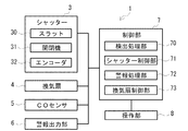
まず、監視領域の開閉システムの構成を説明する。図1は本実施の形態1に係る監視領域の開閉システムの外観を示す斜視図(一部を破断して示す)、図2は図1に示した監視領域の開閉システムの電気的構成を機能概念的に示したブロック図である。図1及び図2に示すように、監視領域の開閉システム1はガレージ2(図2に図示せず)に設置され、シャッター3、換気扇4、一酸化炭素(以下、COという)センサ5、警報出力部6、制御部7(図1に図示せず)、及び、操作部8(図1に図示せず)を備えている。ガレージ2は、開閉自在に設置されたシャッター3を有する前面部2a、壁面部2b、及び屋根部2cを備え、これらに囲繞されたガレージ内部空間に車両等を収容する。
(Configuration of monitoring area switching system)
First, the configuration of the monitoring area switching system will be described. FIG. 1 is a perspective view showing an external appearance of a monitoring area switching system according to the first embodiment (partially cut away), and FIG. 2 functions as an electrical configuration of the monitoring area switching system shown in FIG. It is the block diagram shown conceptually. As shown in FIGS. 1 and 2, a monitoring area opening /
(監視領域の開閉システムの構成−シャッター)
シャッター3は、ガレージ2の内部を外部から遮蔽するためのものであり、特許請求の範囲における遮蔽体に対応している。シャッター3は、スラット30、ガイドレール33(図2に図示せず)、巻取りシャフト34(図2に図示せず)、及び開閉機31(図1に図示せず)を備えている。スラット30は、ガレージ2の内部を遮蔽する遮蔽面となる部分であり、複数の羽根板が相互に回動自在に結合されて構成されている。このスラット30は、ガレージ2の天井近傍において、引出し自在に巻上げ収納されている。開閉機31は、スラット30の巻上げ及び引出しを行うものであり、後述する制御部7によって制御される。この開閉機31に隣接してエンコーダ32が設けられている。エンコーダ32は、開閉機31によるスラット30の巻上げ量を検出する検出手段である。このエンコーダ32としては、公知のロータリエンコーダを用いることができる。
(Configuration of monitoring area switching system-shutter)
The
シャッター3によってガレージ2の内部を遮蔽する場合には、開閉機31によってスラット30が引き出されてガレージ2の内部を遮蔽する。一方、ガレージ2の内部を開放する場合には、開閉機31によってスラット30がガレージ2の天井近傍に巻上げ収納される。
When the interior of the
(監視領域の開閉システムの構成−換気扇)
換気扇4は、ガレージ2の内部を換気するためのものであり、特許請求の範囲における換気手段に対応している。換気扇4の配置位置は任意であり、例えば、図1に示したように、ガレージ2の壁面上部に設置してもよい。また、換気扇4の具体的な構成は任意であり、公知の換気扇を用いることができる。
(Configuration of monitoring area switching system-ventilation fan)
The
(監視領域の開閉システムの構成−COセンサ)
COセンサ5は、ガレージ2の内部に滞留しているCOを検出するためのものであり、特許請求の範囲におけるガス検出手段に対応している。COセンサ5の配置位置は任意であり、例えば、図1に示したように、ガレージ2の天井近傍に配置することができる。なお、COセンサ5によるCO検出の具体的な原理は公知であるため、その説明は省略する。
(Configuration of monitoring area switching system-CO sensor)
The
(監視領域の開閉システムの構成−警報出力部)
警報出力部6は、ガス検出に関する警報を出力するためのものであり、後述する制御部7によって制御される。なお、警報出力部6の設置場所は任意であるが、使用者等に警報が認識されやすい場所であることが望ましく、例えば、ガレージ2の天井近傍や、シャッター3の近傍に設置される。また、警報出力部6によって出力される警報の具体的な態様は任意であり、例えば、音声や画面表示によって出力させてもよい。さらに、ガレージ2に隣接している家屋に設置された受信機等に移報させてもよい。
(Configuration of monitoring area switching system-alarm output unit)
The
(監視領域の開閉システムの構成−制御部)
制御部7は、COセンサ5から入力された情報に基づいてシャッター3を制御するものであり、特許請求の範囲における制御手段に対応している。制御部7は、機能概念的には、検出処理部70、シャッター制御部71、警報処理部72、及び、換気扇制御部73を備えている。検出処理部70は、COセンサ5から入力された信号出力に基づき、ガレージ2の内部のCO濃度算出を行い、算出結果に基づいて処理を行うためのものである。シャッター制御部71は、検出処理部70からの指示に基づいて、シャッター3の制御を行う。シャッター制御部71による具体的なシャッター3の制御方法は任意であり、例えば、リミットスイッチ(例えば、近接スイッチ。図示省略)を追加し、全開ではない開放停止位置を設定し(2段リミットとする)、リレー・タイマ回路を設けて、後述する開閉制御処理においてCO濃度に基づきシャッター3を開放する場合に、シャッター3の停止位置を前記開放停止位置に切り替えることができる。あるいは、タイマを設け、CO濃度に基づいてシャッター3を開放する場合、任意の時間だけシャッター3を開放した後、シャッター電源を遮断し、シャッター3の動作を強制的に停止させることができる。警報処理部72は、検出処理部70からの指示に基づいて、警報出力部6の制御を行う。換気扇制御部73は、検出処理部70からの指示に基づいて、換気扇4の制御を行う。なお、制御部7の具体的構成は任意であるが、例えば、OS(Operating System)などの制御プログラム、各種の処理手順などを規定した組み込みプログラム、所要データを格納するための内部メモリ、及び、これらのプログラムを実行するCPU(Central Processing Unit)を備えて構成される。
(Monitoring area switching system configuration-control unit)
The
(監視領域の開閉システムの構成−操作部)
操作部8は、監視領域の開閉システム1に対する操作を受け付ける部分である。操作部8を介して入力操作が行われると、入力に応じた信号が操作部8から制御部7に出力され、この信号に基づいて制御部7によってシャッター3が制御される。操作部8の具体的な構成は任意であり、例えば、シャッター3の近傍に設置して制御部7と有線接続してもよく、あるいは、操作部8をリモコンとし、無線を用いて制御部7に信号を送信させてもよい。また、操作部8に対する操作項目の具体的な内容についても任意であり、例えば、シャッター3の開閉や、COセンサ5の動作状態、警報の出力状態の切替等に関する操作項目を含めることができる。
(Monitoring area switching system configuration-operation unit)
The
(ガレージにおけるシャッターの開放幅とCO濃度の時間変化との関係)
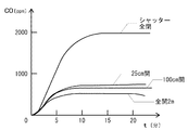
次に、ガレージ2の内部で自動車のエンジンを動作させた場合における、シャッター3の開放幅とCO濃度の時間変化との関係について説明する。図3は、ガレージ2の内部におけるCO濃度の時間変化を示したグラフであり、横軸はエンジン始動からの経過時間、縦軸はガレージ2の内部のCO濃度を表している。この図3には、シャッター3の開放幅を0cm(全閉)、25cm、100cm、200cm(全開)とした場合の各々におけるCO濃度の時間変化が示されている。
(Relationship between shutter opening width and time change of CO concentration in garage)
Next, the relationship between the opening width of the
図3に示したように、ガレージ2の内部におけるCO濃度は時間経過と共に増加し、一定時間の経過後に平衡状態に達する。この平衡状態に達した時点でのCO濃度は、シャッター3の開放幅を0cm(全閉)とした場合は約2000ppm、25cmでは約700ppm、100cmでは約600ppm、200cm(全開)で約400ppmとなっている。この結果から、シャッター3を全開状態とすることにより、シャッター3を全閉状態とした場合と比較して、ガレージ2の内部のCO濃度を大幅に低減できることが分かる。さらに、シャッター3の開放幅を25cmとした場合でも、シャッター3を全開状態とした場合にはわずかに及ばないものの、全閉状態とした場合と比較すると大幅にCO濃度を低減できていることが分る。これは、シャッター3の開放幅を25cmとすることで、ガレージ2の内部の換気性が大幅に向上するためである。
As shown in FIG. 3, the CO concentration inside the
一方、防犯上の観点からは、シャッター3の開放幅をなるべく小さくすることが望ましい。具体的には、人間が通過不可能、あるいは通過が非常に困難な幅とし、侵入を意図する者に対して侵入を躊躇させることが好ましい。例えば、住宅性能表示制度の評価方法基準(最終改正平成19年国土交通省告示第1522号)における評価項目「防犯に関すること」においては、「侵入が可能な規模の開口部」について、「(1)400×250mmの長方形、(2)400×300mmの楕円形、(3)直径が350mmの円、の大きさの断面のブロックのいずれかが通過可能な開口部」として定義されている。すなわち、シャッター3の開口幅を250mm以下とすることで侵入を困難なものとすることができる。従って、シャッター3の開放幅を25cmとすることにより、ガレージ2の内部におけるCO濃度の増加を効果的に抑制できるとともに、防犯性の低下を回避することができる。
On the other hand, from the viewpoint of crime prevention, it is desirable to make the opening width of the
(監視領域の開閉システムにおけるシャッターの制御)
次に、監視領域の開閉システム1におけるシャッター3の制御について説明する。図4は制御部7が実行するシャッター3の開閉制御処理の流れを示すフローチャートである。
(Shutter control in monitoring area opening and closing system)
Next, the control of the
まず、操作部8を介した入力操作によって、ガレージ2の内部のCO濃度監視を開始させる旨の指示が制御部7に対して入力されると、制御部7は、COセンサ5から入力された信号に基づき、検出処理部70を介してガレージ2の内部のCO濃度を監視する。この監視状態においては、制御部7によって、シャッター3は全閉状態とされ、警報出力部6、および換気扇4は停止状態とされている(ステップSA−1)。
First, when an instruction to start monitoring the CO concentration inside the
監視の結果、CO濃度が第2の濃度未満と判定された場合(ステップSA−2、No)、制御部7は上述の監視状態を継続する(ステップSA−1)。一方、CO濃度が第2の濃度以上であり(ステップSA−2、Yes)、かつ、当該第2の濃度よりも高い第1の濃度未満であった場合(ステップSA−3、No)、制御部7は、警報処理部72を介して警報出力部6に第1の警報を出力させると共に(ステップSA−4)、換気扇制御部73を介して換気扇4を動作状態とし、ガレージ2の内部の換気をさせる(ステップSA−5)。その後、制御部7はステップSA−2に戻り、再度CO濃度の判定を行う。ここで、第2の濃度は、緊急性は低いものの、長時間吸気すると人体に害を及ぼす可能性が生じるレベルの濃度として設定されている。
As a result of monitoring, when it is determined that the CO concentration is less than the second concentration (step SA-2, No), the
一方、CO濃度が第1の濃度以上であり(ステップSA−3、Yes)、かつ、当該第1の濃度より高い第3の濃度未満であった場合(ステップSA−6、No)、制御部7は、警報処理部72を介して警報出力部6に第2の警報を出力させると共に(ステップSA−7)、シャッター制御部71を介して開閉機31を動作させ、シャッター3の開放幅が第1の幅となるように当該シャッター3を位置させる(ステップSA−8)。その後、制御部7はステップSA−2に戻り、再度CO濃度の判定を行う。なお、第1の幅をどの程度の開放幅とするかは任意であるが、例えば25cmとすることにより、ガレージ2の内部への不審者の侵入を抑止しつつ、ガレージ2の内部の換気性を確保することができる。また、第1の幅を100cm程度とした場合は、ガレージ2の内部に保管されている自動車の盗難等を防止しつつ、換気性をさらに向上させることができる。ここで、第1の濃度は、短時間のうちに人体に害を及ぼす可能性が高く、早急に換気が必要なレベルの濃度として設定されている。
On the other hand, when the CO concentration is equal to or higher than the first concentration (step SA-3, Yes) and less than the third concentration higher than the first concentration (step SA-6, No), the
ステップSA−6において、CO濃度が第3の濃度以上であった場合(ステップSA−6、Yes)、制御部7は、警報処理部72を介して警報出力部6に第3の警報を出力させると共に(ステップSA−9)、シャッター制御部71を介して開閉機31を動作させ、シャッター3を全開状態にさせる(ステップSA−10)。シャッター3を全開状態とすることにより、最大限の換気性が確保される。その後、制御部7はステップSA−2に戻り、再度CO濃度の判定を行う。ここで、第3の濃度は、吸気すると即座に致命的な状態に至る可能性が高く、緊急に換気が必要となるレベルの濃度として設定されている。
In step SA-6, when the CO concentration is equal to or higher than the third concentration (step SA-6, Yes), the
(実施の形態1の効果)
このように実施の形態1によれば、COセンサ5によって検出されたCOの濃度に応じて、制御部7がシャッター3の開放幅を換気性を確保するために必要な幅に制御するので、防犯性を確保しつつ、必要な換気性を得ることができる。
(Effect of Embodiment 1)
As described above, according to the first embodiment, the
また、CO濃度が第1の濃度以上であった場合には、制御部7は開放幅が第1の幅となるようにシャッター3を位置させるので、ガレージ2内部への不審者の侵入や、当該ガレージ2に保管されている自動車の盗難等を抑止しつつ、十分な換気性を確保することができる。
In addition, when the CO concentration is equal to or higher than the first concentration, the
特に、第1の幅を25cmとすることにより、ガレージ2内部への不審者の侵入を困難とすることができ、且つ、十分な換気性を確保することができる。
In particular, by setting the first width to 25 cm, it is possible to make it difficult for a suspicious person to enter the
また、CO濃度が第1の濃度よりも低い第2の濃度以上となった場合、制御部7は換気扇4を動作させるので、CO濃度が低い場合においてはシャッター3を全閉状態として高い防犯性を維持しつつ、必要な換気性を確保できる。
In addition, when the CO concentration becomes equal to or higher than the second concentration lower than the first concentration, the
〔実施の形態2〕
次に、実施の形態2について説明する。この形態は、物体検出センサを備えた形態である。
[Embodiment 2]
Next, a second embodiment will be described. This form is a form provided with an object detection sensor.
なお、実施の形態2の構成は、特記する場合を除いて実施の形態1の構成と略同一であり、実施の形態1の構成と略同一の構成についてはこの実施の形態1で用いたものと同一の符号及び/又は名称を必要に応じて付して、その説明を省略する。 The configuration of the second embodiment is substantially the same as the configuration of the first embodiment unless otherwise specified. The configuration substantially the same as the configuration of the first embodiment is the same as that used in the first embodiment. The same reference numerals and / or names are attached as necessary, and the description thereof is omitted.
(監視領域の開閉システムの構成−物体検出センサ)
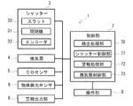
本実施の形態2における、監視領域の開閉システム1について説明する。図5は、本実施の形態2に係る監視領域の開閉システム1の電気的構成を機能概念的に示したブロック図である。本実施の形態2では、監視領域の開閉システム1は物体検出センサ9を備えている。この物体検出センサ9は、シャッター3の動作範囲に存在する物体を検出する検出手段である。なお、物体検出センサ9による物体の検出方法任意であり、例えば赤外線、超音波、マイクロ波振動等を利用して物体の検出を行わせることができる。これらの検出方法の詳細については公知の技術であるので説明を省略する。
(Configuration of monitoring area switching system-object detection sensor)
A monitoring area opening /
(監視領域の開閉システムの構成−検出処理部)
本実施の形態2における検出処理部70は、COセンサ5から入力された信号出力に基づく処理に加えて、物体検出センサ9から入力された信号出力に基づき、シャッター3の動作範囲における物体の有無の判定を行い、当該判定結果に基づいて処理を行う。
(Configuration of monitoring area switching system-detection processing unit)
The
(監視領域の開閉システムにおけるシャッターの制御)
次に、本実施の形態2における、監視領域の開閉システム1におけるシャッター3の制御について説明する。図6は制御部7が実行するシャッター3の開閉制御処理の流れを示すフローチャートである。
(Shutter control in monitoring area opening and closing system)
Next, control of the
ここで、ステップSB−1からSB−10は、上述のステップSA−1からSA−10までと同様であるので、説明を省略する。 Here, Steps SB-1 to SB-10 are the same as Steps SA-1 to SA-10 described above, and a description thereof will be omitted.
ステップSB−8においてシャッター3の開放幅が25cmとされた後、あるいは、ステップSB−10においてシャッター3が全開状態とされた後、制御部7は、物体検出センサ9から入力された信号に基づき、検出処理部70を介してシャッター3の動作範囲における物体の有無を監視する。その結果、シャッター3の動作範囲に物体の存在が検出された場合(ステップSB−11、Yes)、制御部7はガレージ2の内部に対する侵入の可能性があるものと判断し、警報処理部72を介してその旨を示す第4の警報を警報出力部6に出力させる(ステップSB−12)。第4の警報を出力した後、あるいは物体の存在が検出されなかった場合(ステップSB−11、No)、制御部7はステップSB−2に戻り、再度CO濃度の判定を行う。
After the opening width of the
(実施の形態2の効果)
このように実施の形態2によれば、換気性を確保するためにシャッター3を開放させている場合において、物体検出センサ9を用いてシャッター3の動作範囲における物体を検出させると共に、物体検出時には警報を出力させることができる。これにより、必要な換気性を確保しつつ、ガレージ2に対する不審者の侵入を通報することができ、防犯性を高めることができる。
(Effect of Embodiment 2)
As described above, according to the second embodiment, when the
〔III〕各実施の形態に対する変形例
以上、本発明に係る各実施の形態について説明したが、本発明の具体的な構成及び手段は、特許請求の範囲に記載した各発明の技術的思想の範囲内において、任意に改変及び改良することができる。以下、このような変形例について説明する。
[III] Modifications to Each Embodiment While each embodiment according to the present invention has been described above, the specific configuration and means of the present invention are the same as the technical idea of each invention described in the claims. Modifications and improvements can be arbitrarily made within the range. Hereinafter, such a modification will be described.
(解決しようとする課題や発明の効果について)
まず、発明が解決しようとする課題や発明の効果は、前記した内容に限定されるものではなく、本発明によって、前記に記載されていない課題を解決したり、前記に記載されていない効果を奏することもでき、また、記載されている課題の一部のみを解決したり、記載されている効果の一部のみを奏することがある。
(About problems to be solved and effects of the invention)
First, the problems to be solved by the invention and the effects of the invention are not limited to the above-described contents, and the present invention solves the problems not described above or has the effects not described above. There are also cases where only some of the described problems are solved or only some of the described effects are achieved.
(ガス検出手段について)
上述の各実施の形態においては、ガス検出手段としてCOセンサを用いた場合を説明したが、COセンサに限らず、ニオイセンサ、NOxセンサ、O2センサ、CO2センサ等を用いて空気清浄度を検出させ、検出値に応じてシャッター3を制御してもよい。
(About gas detection means)
In each of the above-described embodiments, the case where the CO sensor is used as the gas detection unit has been described. However, not only the CO sensor but also an odor sensor, a NOx sensor, an O 2 sensor, a CO 2 sensor, and the like are used. May be detected, and the
(シャッターについて)
上述の各実施の形態においては、シャッター3がスラットを吊り上げる形態のシャッターである場合を例示して説明したが、観音開きタイプや、スラットを巻き取らずにそのまま天井内にスライドして格納するタイプのシャッターを用いてもよい。
(About shutter)
In each of the above-described embodiments, the case where the
(物体検出センサについて)
上述の実施の形態2においては、監視領域の開閉システム1は物体検出センサ9を備えているが、当該物体検出センサ9を、シャッター3による挟み込み防止のためのセンサとして共用するように構成してもよい。これにより、COが検出されていない通常状態でのシャッター3の開閉時において物体検出センサ9によりシャッター3の動作範囲に物体が検出された場合、制御部7によってシャッター3の動作を緊急停止させ、安全を確保させることができる。
(About the object detection sensor)
In the second embodiment described above, the monitoring area opening /
この発明に係る監視領域の開閉システムは、ガレージ等の監視領域を遮蔽するシャッター等の遮蔽体を開閉するための、監視領域の開閉システムに適用でき、十分な換気性と防犯性とを両立可能な監視領域の開閉システムに有用である。 The monitoring area opening and closing system according to the present invention can be applied to a monitoring area opening and closing system for opening and closing a shielding body such as a shutter for shielding a monitoring area such as a garage, and can achieve both sufficient ventilation and crime prevention. This is useful for opening and closing systems for various monitoring areas.
1 監視領域の開閉システム
2 ガレージ
2a 前面部
2b 壁面部
2c 屋根部
3 シャッター
4 換気扇
5 COセンサ
6 警報出力部
7 制御部
8 操作部
9 物体検出センサ
30 スラット
31 開閉機
32 エンコーダ
33 ガイドレール
34 巻取りシャフト
70 検出処理部
71 シャッター制御部
72 警報処理部
73 換気扇制御部
DESCRIPTION OF
Claims (5)
前記監視領域における検出対象ガスを検出するガス検出手段と、
前記ガス検出手段によって検出された前記検出対象ガスの濃度に基づいて、前記遮蔽体の位置制御を行う制御手段と、
を備えることを特徴とする監視領域の開閉システム。 A shield that can be opened and closed with respect to the monitoring area;
Gas detection means for detecting a detection target gas in the monitoring region;
Control means for controlling the position of the shield based on the concentration of the detection target gas detected by the gas detection means;
A system for opening and closing a monitoring area, comprising:
を特徴とする請求項1に記載の監視領域の開閉システム。 In the case where the monitoring area is closed by the shield, the control means is configured to detect the detection target gas detected by the gas detection means when the concentration of the detection target gas is equal to or higher than a first concentration. Positioning the shield so that the open width of the shield is the first width;
The monitoring area opening and closing system according to claim 1.
を特徴とする請求項2に記載の監視領域の開閉システム。 The first width is narrower than the minimum width that can pass through the human body;
The monitoring area opening and closing system according to claim 2.
前記制御手段は、前記ガス検出手段によって検出された前記検出対象ガスの濃度が前記第1の濃度よりも低い第2の濃度以上であった場合、前記換気手段を動作させること、
を特徴とする請求項2または3に記載の監視領域の開閉システム。 A ventilation means for ventilating the monitoring area;
The control means operates the ventilation means when the concentration of the detection target gas detected by the gas detection means is equal to or higher than a second concentration lower than the first concentration;
The monitoring area opening and closing system according to claim 2 or 3.
前記制御手段は、前記ガス検出手段によって検出された前記検出対象ガスの濃度に基づいて前記遮蔽体の位置制御を行った場合において、前記物体検出センサによって前記遮蔽体の動作範囲に物体が検出された場合、当該物体が検出された旨を示す警報信号を出力すること、
を特徴とする請求項1から4のいずれか一項に記載の監視領域の開閉システム。 An object detection sensor for detecting an object present in the operating range of the shield;
When the control unit performs position control of the shield based on the concentration of the detection target gas detected by the gas detection unit, an object is detected in the operating range of the shield by the object detection sensor. Output a warning signal indicating that the object has been detected,
The monitoring area opening and closing system according to any one of claims 1 to 4.
Priority Applications (1)
| Application Number | Priority Date | Filing Date | Title |
|---|---|---|---|
| JP2008181865A JP5297710B2 (en) | 2008-07-11 | 2008-07-11 | Monitoring area switching system |
Applications Claiming Priority (1)
| Application Number | Priority Date | Filing Date | Title |
|---|---|---|---|
| JP2008181865A JP5297710B2 (en) | 2008-07-11 | 2008-07-11 | Monitoring area switching system |
Publications (2)
| Publication Number | Publication Date |
|---|---|
| JP2010019029A true JP2010019029A (en) | 2010-01-28 |
| JP5297710B2 JP5297710B2 (en) | 2013-09-25 |
Family
ID=41704195
Family Applications (1)
| Application Number | Title | Priority Date | Filing Date |
|---|---|---|---|
| JP2008181865A Active JP5297710B2 (en) | 2008-07-11 | 2008-07-11 | Monitoring area switching system |
Country Status (1)
| Country | Link |
|---|---|
| JP (1) | JP5297710B2 (en) |
Cited By (3)
| Publication number | Priority date | Publication date | Assignee | Title |
|---|---|---|---|---|
| JP2015227592A (en) * | 2014-06-02 | 2015-12-17 | トヨタホーム株式会社 | Ventilation system |
| JP2018073160A (en) * | 2016-10-31 | 2018-05-10 | 新コスモス電機株式会社 | Alarm |
| JP2019027159A (en) * | 2017-07-31 | 2019-02-21 | 三和シヤッター工業株式会社 | Open/close control system |
Citations (13)
| Publication number | Priority date | Publication date | Assignee | Title |
|---|---|---|---|---|
| JPS55142883A (en) * | 1979-04-19 | 1980-11-07 | Hitachi Ltd | Garage door controller |
| JPS573976A (en) * | 1980-06-11 | 1982-01-09 | Hitachi Ltd | Garage door controller |
| JPS5819645A (en) * | 1981-07-30 | 1983-02-04 | Norisue Ishihara | Opening device with ventilator |
| JPH047484A (en) * | 1990-04-24 | 1992-01-10 | Matsushita Electric Works Ltd | Automatic opening and closing device |
| JPH05280272A (en) * | 1992-03-27 | 1993-10-26 | Sanwa Shutter Corp | Automatic closing device for balance type motor-driven shutter |
| JPH05340174A (en) * | 1992-06-05 | 1993-12-21 | Yoshida Kogyo Kk <Ykk> | Opening and shutting controller for slit-equipped shutter |
| JPH06173541A (en) * | 1991-01-09 | 1994-06-21 | La-Ku:Kk | House ventilator |
| JPH1122295A (en) * | 1997-07-07 | 1999-01-26 | Yutaka Denshi Seisakusho:Kk | Sash-window control system |
| JP2003223684A (en) * | 2002-01-30 | 2003-08-08 | Panahome Corp | Burglar prevention device |
| JP2005061028A (en) * | 2003-08-11 | 2005-03-10 | Sumori Kogyo Kk | Automatic opening/closing door material |
| JP2006241676A (en) * | 2005-02-28 | 2006-09-14 | Ykk Ap株式会社 | Fittings |
| JP2008144519A (en) * | 2006-12-12 | 2008-06-26 | Aisin Seiki Co Ltd | Building window automatic opening-closing device |
| JP2009138352A (en) * | 2007-12-04 | 2009-06-25 | Toyota Motor Corp | Building |
-
2008
- 2008-07-11 JP JP2008181865A patent/JP5297710B2/en active Active
Patent Citations (13)
| Publication number | Priority date | Publication date | Assignee | Title |
|---|---|---|---|---|
| JPS55142883A (en) * | 1979-04-19 | 1980-11-07 | Hitachi Ltd | Garage door controller |
| JPS573976A (en) * | 1980-06-11 | 1982-01-09 | Hitachi Ltd | Garage door controller |
| JPS5819645A (en) * | 1981-07-30 | 1983-02-04 | Norisue Ishihara | Opening device with ventilator |
| JPH047484A (en) * | 1990-04-24 | 1992-01-10 | Matsushita Electric Works Ltd | Automatic opening and closing device |
| JPH06173541A (en) * | 1991-01-09 | 1994-06-21 | La-Ku:Kk | House ventilator |
| JPH05280272A (en) * | 1992-03-27 | 1993-10-26 | Sanwa Shutter Corp | Automatic closing device for balance type motor-driven shutter |
| JPH05340174A (en) * | 1992-06-05 | 1993-12-21 | Yoshida Kogyo Kk <Ykk> | Opening and shutting controller for slit-equipped shutter |
| JPH1122295A (en) * | 1997-07-07 | 1999-01-26 | Yutaka Denshi Seisakusho:Kk | Sash-window control system |
| JP2003223684A (en) * | 2002-01-30 | 2003-08-08 | Panahome Corp | Burglar prevention device |
| JP2005061028A (en) * | 2003-08-11 | 2005-03-10 | Sumori Kogyo Kk | Automatic opening/closing door material |
| JP2006241676A (en) * | 2005-02-28 | 2006-09-14 | Ykk Ap株式会社 | Fittings |
| JP2008144519A (en) * | 2006-12-12 | 2008-06-26 | Aisin Seiki Co Ltd | Building window automatic opening-closing device |
| JP2009138352A (en) * | 2007-12-04 | 2009-06-25 | Toyota Motor Corp | Building |
Cited By (3)
| Publication number | Priority date | Publication date | Assignee | Title |
|---|---|---|---|---|
| JP2015227592A (en) * | 2014-06-02 | 2015-12-17 | トヨタホーム株式会社 | Ventilation system |
| JP2018073160A (en) * | 2016-10-31 | 2018-05-10 | 新コスモス電機株式会社 | Alarm |
| JP2019027159A (en) * | 2017-07-31 | 2019-02-21 | 三和シヤッター工業株式会社 | Open/close control system |
Also Published As
| Publication number | Publication date |
|---|---|
| JP5297710B2 (en) | 2013-09-25 |
Similar Documents
| Publication | Publication Date | Title |
|---|---|---|
| JP5033727B2 (en) | Remote control device for shutter | |
| US20070146150A1 (en) | Carbon monoxide poisoning avoidance system | |
| JP2010112044A (en) | Security system | |
| JP5297710B2 (en) | Monitoring area switching system | |
| JP2010071012A (en) | Air conditioning system for building | |
| JP5874028B2 (en) | Crime prevention system | |
| JP2010146190A (en) | Crime-prevention system | |
| JP4796380B2 (en) | Building security equipment | |
| JP2003228783A (en) | Security system | |
| CN213418920U (en) | Fireproof intelligent door and window | |
| KR100745555B1 (en) | Fire prevention screen device for windows and doors of house outer wall | |
| JP5254567B2 (en) | Intrusion monitoring area opening and closing system | |
| JP2005004633A (en) | Crime prevention system | |
| JP2004062548A (en) | Security-and-alarm device using electrically openable/closable door body | |
| JP2005155283A (en) | Automatic door system | |
| US20120285088A1 (en) | Safety system for a door opener | |
| US20180283099A1 (en) | Command and confirm electronic shutter systems | |
| CN211598217U (en) | Smart window system based on diversified sensor | |
| JP5088872B2 (en) | Door open / close detection sensor | |
| KR20140050358A (en) | A smoke eliminating vent | |
| JP2015094106A (en) | Ventilation system of building | |
| JP2010122775A (en) | Security system for building | |
| JP2014026426A (en) | Monitoring system | |
| JP5351716B2 (en) | Building ventilation system | |
| JP6751372B2 (en) | Building security system |
Legal Events
| Date | Code | Title | Description |
|---|---|---|---|
| A621 | Written request for application examination |
Free format text: JAPANESE INTERMEDIATE CODE: A621 Effective date: 20110119 |
|
| A977 | Report on retrieval |
Free format text: JAPANESE INTERMEDIATE CODE: A971007 Effective date: 20120613 |
|
| A131 | Notification of reasons for refusal |
Free format text: JAPANESE INTERMEDIATE CODE: A131 Effective date: 20120620 |
|
| A521 | Request for written amendment filed |
Free format text: JAPANESE INTERMEDIATE CODE: A523 Effective date: 20120817 |
|
| TRDD | Decision of grant or rejection written | ||
| A01 | Written decision to grant a patent or to grant a registration (utility model) |
Free format text: JAPANESE INTERMEDIATE CODE: A01 Effective date: 20130529 |
|
| A61 | First payment of annual fees (during grant procedure) |
Free format text: JAPANESE INTERMEDIATE CODE: A61 Effective date: 20130617 |
|
| R150 | Certificate of patent or registration of utility model |
Ref document number: 5297710 Country of ref document: JP Free format text: JAPANESE INTERMEDIATE CODE: R150 Free format text: JAPANESE INTERMEDIATE CODE: R150 |
|
| R250 | Receipt of annual fees |
Free format text: JAPANESE INTERMEDIATE CODE: R250 |
|
| R250 | Receipt of annual fees |
Free format text: JAPANESE INTERMEDIATE CODE: R250 |
|
| R250 | Receipt of annual fees |
Free format text: JAPANESE INTERMEDIATE CODE: R250 |
|
| R250 | Receipt of annual fees |
Free format text: JAPANESE INTERMEDIATE CODE: R250 |
|
| R250 | Receipt of annual fees |
Free format text: JAPANESE INTERMEDIATE CODE: R250 |
|
| R250 | Receipt of annual fees |
Free format text: JAPANESE INTERMEDIATE CODE: R250 |
|
| R250 | Receipt of annual fees |
Free format text: JAPANESE INTERMEDIATE CODE: R250 |
|
| R250 | Receipt of annual fees |
Free format text: JAPANESE INTERMEDIATE CODE: R250 |