JP2010017783A - Method and device for suppressing vibration - Google Patents
Method and device for suppressing vibration Download PDFInfo
- Publication number
- JP2010017783A JP2010017783A JP2008178300A JP2008178300A JP2010017783A JP 2010017783 A JP2010017783 A JP 2010017783A JP 2008178300 A JP2008178300 A JP 2008178300A JP 2008178300 A JP2008178300 A JP 2008178300A JP 2010017783 A JP2010017783 A JP 2010017783A
- Authority
- JP
- Japan
- Prior art keywords
- value
- vibration
- rotational speed
- frequency
- rotation speed
- Prior art date
- Legal status (The legal status is an assumption and is not a legal conclusion. Google has not performed a legal analysis and makes no representation as to the accuracy of the status listed.)
- Granted
Links
Images


Landscapes
- Automatic Control Of Machine Tools (AREA)
- Numerical Control (AREA)
Abstract
Description
本発明は、工具又はワークを回転させながら加工を行う工作機械において、加工中に発生する振動を抑制する方法、及び当該方法を実行可能な振動抑制装置に関するものである。 The present invention relates to a method for suppressing vibration generated during processing in a machine tool that performs processing while rotating a tool or a workpiece, and a vibration suppression device capable of executing the method.
従来、工作機械の振動抑制方法としては、たとえば特許文献1に記載の方法が知られている。この振動抑制方法では、加工面の仕上げ精度悪化の原因となる自励振動としての再生型びびり振動を抑制するため、工具やワーク等といったびびり振動が生じる系の固有振動数を求め、これを60倍すると共に工具刃数及び所定の整数で除して得た値を安定回転速度とする。そして、当該安定回転速度にて加工を行うことにより、加工中に発生するびびり振動を抑制しようとしている。なお、固有振動数は、工具やワークをインパルス加振することにより得ている。
Conventionally, for example, a method described in
また、特許文献2に記載の振動抑制方法も知られている。この振動抑制方法は、びびり振動が生じる系の加工中のびびり周波数を求め、これを60倍すると共に工具刃数及び所定の整数で除した値を安定回転速度として加工を行うことにより、びびり振動を抑制しようとするものである。なお、加工中のびびり周波数は、工具やワークの近傍に音センサを配置し、回転中に音センサで検出された振動周波数に基づいて得ている。
A vibration suppression method described in
しかしながら、特許文献1に記載の振動抑制方法では、高価なインパルス装置が必要となる上、この装置を用いた加振には高度な技術を要し、手間がかかる。しかも、加工前に得た固有振動数と加工中に発生するびびり振動数とは必ずしも一致しないため、正確な安定回転速度を得にくいという問題もある。
一方、特許文献2に記載の振動抑制方法では、回転音等の分析により得られたびびり周波数と実際に発生しているびびり振動数(固有振動数)とが互いにやや異なった値となるため、やはり正確な安定回転速度を得にくい。このため、本件出願人は、回転中の回転軸の時間領域の振動を検出する検出手段と、その時間領域の振動に基づいてびびり振動数等を算出する演算手段とを設置して、より正確なびびり振動数を求め、更に最適な安定回転速度を得ようとした振動抑制装置(たとえば、特願2007−138166)を考案した。しかしながら、当該振動抑制装置では、検出手段の検出誤差に起因して、演算手段が算出したびびり振動数と実際に発生しているびびり振動数との間に計算誤差が生じ、回転軸を安定回転速度としたにも拘わらず、びびり振動が継続してしまう事態が考えられる。
However, the vibration suppression method described in
On the other hand, in the vibration suppression method described in
そこで、本発明は、上記問題に鑑みなされたものであって、びびり振動が継続するような場合に、より正確な安定回転速度を得ることができ、びびり振動を確実に抑制することができる振動抑制方法及び装置を提供しようとするものである。 Therefore, the present invention has been made in view of the above problems, and in the case where chatter vibration continues, a more accurate stable rotational speed can be obtained, and vibration that can reliably suppress chatter vibration. It is an object of the present invention to provide a suppression method and apparatus.
上記目的を達成するために、本発明のうち請求項1に記載の発明は、工具又はワークを回転させるための回転軸を備えた工作機械において、前記回転軸を回転させた際に生じるびびり振動を抑制するための振動抑制方法であって、回転中の前記回転軸による時間領域の振動を検出する第1ステップと、検出した時間領域の振動にもとづいて、びびり周波数及び該びびり周波数における周波数領域の振動加速度を算出する第2ステップと、算出した周波数領域の振動加速度が所定の閾値を超えた場合に、下記の演算式(1)、(2)によりk値及びk’値を算出し、加工情報として記憶する第3ステップと、算出したk値を用いて下記の演算式(3)により、予想安定回転速度を算出し、前記回転軸の回転速度を予想安定回転速度とする第4ステップと、予想安定回転速度にて回転中の前記回転軸において、再び周波数領域の振動加速度が所定の閾値を超えた場合、前記回転軸の回転速度を前記予想安定回転速度から変化させる第5ステップとを実行することを特徴とするものである。
演算式(1):k’値={60×びびり周波数/(工具刃数×回転速度)}
演算式(2):k値=k’値の整数部
演算式(3):予想安定回転速度=60×びびり周波数/{(工具刃数×(k値+1)}
尚、請求項1に記載の第1ステップにより検出される「振動」とは、振動加速度、振動による変位、及び振動による音圧等、振動自体は勿論、振動に起因して回転軸に発生し、間接的に振動を検出することができる物理的変化を含むものである。
In order to achieve the above object, the invention according to
Formula (1): k ′ value = {60 × chatter frequency / (number of tool blades × rotational speed)}
Operational expression (2): k value = integer part expression of k ′ value (3): expected stable rotation speed = 60 × chat frequency / {(number of tool blades × (k value + 1)}
The “vibration” detected by the first step described in
請求項2に記載の発明は、請求項1に記載の発明において、第5ステップを実行した後、さらに周波数領域の振動加速度が所定の閾値を超えた場合、変化後の回転速度を用いて前記演算式(1)同様の演算式によりk”値を算出する第6ステップと、算出したk”値と加工情報として記憶されているk’値との差である変化量と、所定の位相閾値とを比較し、前記変化量が前記位相閾値を超えない場合、k”値をk’値として更新する第7ステップと、前記変化量が前記位相閾値を超えるまで、回転速度の変化、k”値の算出、及びk’値の更新を繰り返し、前記変化量が前記位相閾値を超えた際の回転速度を安定回転速度として維持する第8ステップとを実行することを特徴とするものである。
請求項3に記載の発明は、請求項1に記載の発明において、前記第3ステップにおいて、周波数領域の振動加速度が所定の閾値を超えた際のびびり周波数を加工情報として記憶するとともに、第5ステップを実行した後、さらに周波数領域の振動加速度が所定の閾値を超えた場合、今回のびびり周波数と前記加工情報として記憶されているびびり周波数との変化量を求め、当該変化量が所定の位相閾値を超えるまで回転速度を変化させ、前記変化量が所定の位相閾値を超えた回転速度を安定回転速度として維持するステップを実行することを特徴とするものである。
請求項4に記載の発明は、請求項1〜3のいずれかに記載の発明において、前記第5ステップにおいて回転速度を変化させるにあたり、k’値の小数部と所定の変更方向決定閾値とを比較して、回転速度の増減を決定することを特徴とするものである。
According to a second aspect of the present invention, in the first aspect of the present invention, when the vibration acceleration in the frequency domain exceeds a predetermined threshold after executing the fifth step, the rotational speed after the change is used. Calculation Formula (1) A sixth step of calculating the k ″ value by the same calculation formula, a change amount that is a difference between the calculated k ″ value and the k ′ value stored as the processing information, and a predetermined phase threshold value And when the change amount does not exceed the phase threshold value, the seventh step of updating the k ″ value as the k ′ value, and the change in rotational speed until the change amount exceeds the phase threshold value, k ″ The calculation of the value and the update of the k ′ value are repeated, and the eighth step of maintaining the rotational speed when the change amount exceeds the phase threshold value as the stable rotational speed is executed.
According to a third aspect of the present invention, in the first aspect of the present invention, in the third step, the chatter frequency when the vibration acceleration in the frequency domain exceeds a predetermined threshold is stored as machining information. After the step is executed, if the vibration acceleration in the frequency domain exceeds a predetermined threshold, the amount of change between the current chatter frequency and the chatter frequency stored as the machining information is obtained, and the amount of change is a predetermined phase. The rotational speed is changed until it exceeds a threshold value, and the step of maintaining the rotational speed at which the change amount exceeds a predetermined phase threshold value as a stable rotational speed is executed.
According to a fourth aspect of the present invention, in the invention according to any one of the first to third aspects, when changing the rotation speed in the fifth step, a decimal part of a k ′ value and a predetermined change direction determination threshold value are set. In comparison, the increase / decrease in the rotational speed is determined.
一方、請求項5に記載の発明は、工具又はワークを回転させるための回転軸を備えた工作機械において、前記回転軸を回転させた際に生じるびびり振動を抑制するための振動抑制装置であって、回転中の前記回転軸の時間領域の振動を検出する検出手段と、検出した時間領域の振動にもとづいて、びびり周波数及び該びびり周波数における周波数領域の振動加速度を算出する第1演算手段と、算出した周波数領域の振動加速度が所定の閾値を超えた場合に、下記の演算式(1)、(2)によりk値及びk’値を、下記の演算式(3)により予想安定回転速度を夫々算出する第2演算手段と、前記k値及びk’値を加工情報として記憶する記憶手段と、前記回転軸の回転速度を制御する回転速度制御手段とを備えているとともに、前記第2演算手段により算出された予想安定回転速度にて回転中の前記回転軸において、再び周波数領域の振動加速度が所定の閾値を超えた場合、前記回転軸の回転速度を前記予想安定回転速度から変化させることを特徴とするものである。
演算式(1):k’値={60×びびり周波数/(工具刃数×回転速度)}
演算式(2):k値=k’値の整数部
演算式(3):予想安定回転速度=60×びびり周波数/{(工具刃数×(k値+1)}
尚、請求項5において検出手段が検出する「振動」も、請求項1に記載の「振動」と同様のものである。
On the other hand, the invention according to
Formula (1): k ′ value = {60 × chatter frequency / (number of tool blades × rotational speed)}
Operational expression (2): k value = integer part expression of k ′ value (3): expected stable rotation speed = 60 × chat frequency / {(number of tool blades × (k value + 1)}
The “vibration” detected by the detecting means in
本発明によれば、予想安定回転速度において回転中の回転軸に再び「びびり振動」が生じた際、予想安定回転速度をベースとして回転軸の回転速度を変化させて対応するため、断続的に発生する「びびり振動」を従来以上に効果的に抑制することができ、ひいては加工面の品位の向上、工具摩耗の抑制等を図ることができる。
また、回転速度を変化させた際のk’値の変化量やびびり周波数の変化量を求め、位相閾値と比較する等して安定回転速度を決定することで、より正確な安定回転速度を得ることができ、「びびり振動」を極めて効果的に抑制することができる。
According to the present invention, when “chatter vibration” occurs again on the rotating shaft that is rotating at the predicted stable rotational speed, the rotational speed of the rotating shaft is changed based on the predicted stable rotational speed. The generated “chatter vibration” can be suppressed more effectively than before, and as a result, the quality of the machined surface can be improved, and the wear of the tool can be suppressed.
In addition, a more accurate stable rotational speed can be obtained by determining the stable rotational speed by determining the amount of change in k ′ value and the amount of chatter frequency when the rotational speed is changed and comparing it with a phase threshold value. Therefore, “chatter vibration” can be extremely effectively suppressed.
以下、本発明の一実施形態となる振動抑制方法及び装置について、図面をもとに説明する。
図1は、振動抑制装置10のブロック構成説明図である。図2は、振動抑制の対象となる回転軸ハウジング1を側方から示した説明図であり、図3は、回転軸ハウジング1を軸方向から示した説明図である。
Hereinafter, a vibration suppressing method and apparatus according to an embodiment of the present invention will be described with reference to the drawings.
FIG. 1 is a block diagram illustrating the
振動抑制装置10は、回転軸ハウジング1にC軸周りで回転可能に備えられた回転軸3に発生する「びびり振動」を抑制するためのものであって、回転中の回転軸3に生じる時間領域の振動加速度(時間軸上の振動加速度を意味する)を検出するための振動センサ(検出手段)2a〜2cと、振動センサ2a〜2cによる検出値をもとにして回転軸3の回転速度を制御する制御装置5とからなる。
The
振動センサ2a〜2cは、図2や図3に示すように、互いに直角となる方向における時間領域の振動加速度を検出すべく、互いに直交するX軸、Y軸、Z軸方向での時間領域の振動加速度を検出可能な状態で、回転軸ハウジング1に取り付けられている。
As shown in FIGS. 2 and 3, the
また、制御装置5は、振動センサ2a〜2cにより検出された時間領域の振動加速度をもとにフーリエ解析を行うFFT演算装置11と、FFT演算装置11で算出された値にもとづいて安定回転速度の算出等を行う演算装置12と、回転軸ハウジング1での加工を制御するNC装置(回転速度制御手段)13と、演算装置12にて算出された各種数値を記憶する記憶装置14とを備えている。なお、NC装置13は、回転軸3の回転速度をモニタリングしている。
The
ここで、上述したような振動抑制装置10による「びびり振動」の振動抑制方法について、図7及び図8のフローチャートをもとに説明する。
加工開始当初、制御装置5は、図7のフローチャートにもとづいて回転軸3の回転動作を制御する。
まず、FFT演算装置11では、振動センサ2a〜2cによって回転軸3の回転中に常時検出される時間領域の振動加速度についてフーリエ解析を行い(S1)、図4に示すような最大加速度(周波数領域の振動加速度)及びその周波数4(びびり周波数)を常時計算している(S2)。なお、時間領域の振動加速度についてフーリエ解析を行うと、周波数と周蓮領域の振動加速度との関係を示す図4のような波形が複数パターン取得されるが、本実施形態では、周波数領域の振動加速度が最大となる波形を用いる。
Here, the vibration suppressing method of “chatter vibration” by the
At the beginning of machining, the
First, the FFT
次に、演算装置12では、FFT演算装置11において算出された周波数領域の振動加速度と予め設定されている所定の閾値とを比較し(S3)、周波数領域の振動加速度が所定の閾値を超えた場合(例えば、図4における周波数4での周波数領域の振動加速度が検出された場合)には、回転軸3に抑制すべき「びびり振動」が発生しているとして、下記演算式(1)、(2)によりk’値及びk値を算出するとともに、k’値及びk値に加え、その周波数領域の振動加速度(すなわち最大加速度)及び周波数4を加工情報として記憶装置14に記憶する(S4)。また、下記演算式(3)により予想安定回転速度を算出し、NC装置13へ出力し、回転軸3の回転速度を予想安定回転速度に変更する(S5)。
Next, the
k’値={60×びびり周波数/(工具刃数×回転速度)}・・・ (1)
k値=k’値の整数部・・・(2)
予想安定回転速度=60×びびり周波数/{(工具刃数×(k値+1)}・・・(3)
ここで、演算式(1)、(3)における「工具刃数」は、予め演算装置12に設定されているものとする。また、演算式(1)における「回転速度」とは、予想安定回転速度とする前の現在の回転速度のことである。さらに、びびり周波数とは、「びびり振動」が発生した場合の周波数4のことである。
k ′ value = {60 × chat frequency / (number of tool blades × rotational speed)} (1)
k value = integer part of k ′ value (2)
Expected stable rotation speed = 60 × chat frequency / {(number of tool blades × (k value + 1)} (3)
Here, it is assumed that “the number of tool blades” in the calculation formulas (1) and (3) is set in the
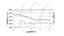
以上のようにして算出した予想安定回転速度により回転軸3を回転させると、図5に示す如く、びびり周波数(周波数4)における振動加速度7は2割程度しか減少しない。したがって、「びびり振動」を一応抑制することができるとして算出した予想安定回転速度で回転軸3を回転させているにも拘わらず、周波数領域における振動加速度が再び閾値を超える、すなわち「びびり振動」が断続的に発生する事態が起こり得る。そこで、制御装置5は、予想安定回転速度にて回転軸3を回転させた後には、図8に示すフローチャートにもとづいて回転軸3の回転動作を制御する。尚、図5における6は、回転速度を示している。
When the
上述したように、FFT演算装置11では、予想安定回転速度による回転中も振動センサ2a〜2cによって回転軸3の回転中に常時検出される時間領域の振動加速度についてフーリエ解析及び、最大加速度とその周波数4(びびり周波数)との計算を継続する(S11)とともに、演算装置12では、FFT演算装置11において算出された周波数領域の振動加速度と予め設定されている所定の閾値との比較を行う(S12)。そして、所定の閾値を超える周波数領域の振動加速度が再び検出された場合、記憶装置14に記憶しているk’値の小数部と予め設定されている変更方向決定閾値(例えば0.5)との下記関係から回転軸3の回転速度の増減を決定し、当該決定にもとづいて回転速度を微小変化させるようにNC装置13へ指令する(S13)。そして、NC装置13では、演算装置12からの指令に応じて回転軸3の回転速度を微小変化させる。ここで、k’値の小数部と予め設定されている変更方向決定閾値との関係とは、k’値の小数部が変更方向決定閾値以上であった場合には回転速度を減少させ、k’値の小数部が変更方向決定閾値未満であった場合には回転速度を増大させるというものである。また、回転速度を微小変化させるにあたっての変更量は、回転速度の数%程度(たとえば2%)とする。
As described above, the FFT
また、振動抑制装置10は、回転速度の微小変更後にも、FFT演算装置11及び演算装置12によるS11及びS12同様のフーリエ解析及び周波数領域の振動加速度と所定の閾値との比較を継続する(S14)。そして、演算装置12では、所定の閾値を超える振動加速度が再度検出されると、当該微小変更後の回転速度と、S14で所定の閾値を超えた振動加速度におけるびびり周波数と、工具刃数とから、上記演算式(1)と同様の演算式にて、k”値を算出する(S15)。また、算出したk”値と記憶装置14に記憶されているk’値とから下記演算式(4)により変化量を求める。
変化量=k’値−k”値・・・(4)
Further, even after the minute change of the rotation speed, the
Change amount = k ′ value−k ″ value (4)
さらに、演算装置12では、変化量と予め設定されている位相閾値(たとえば、0.4)とを比較し(S16)、変化量が位相閾値を超えない場合には、求めたk”値をk’値として記憶装置14に上書き更新し(S17)た後、S13へ戻って回転速度を更に微小変化させ、フーリエ解析にもとづく監視を継続しながら「びびり振動」が収まらない場合には変化量を求めるといった上記制御を繰り返し実行する。
一方、S16における比較の結果、変化量が位相閾値を超えた場合、及び回転速度を微小変化させた結果、「びびり振動」が検出されなくなった場合(すなわち、所定の閾値を超える周波数領域の振動加速度が検出されなくなった場合)には、その回転速度が安定回転速度であるとして、NC装置13へ回転速度を維持するように出力する(S18)。そして、演算装置12からの回転速度の維持に係る出力を受けたNC装置13は、回転軸3の回転速度を、その回転速度で維持(すなわち、安定回転速度で維持)する。したがって、「びびり振動」が抑制された安定加工状態が維持されることになる。
Further, the
On the other hand, as a result of the comparison in S16, when the amount of change exceeds the phase threshold, and as a result of minutely changing the rotation speed, “chatter vibration” is not detected (that is, vibration in the frequency domain exceeding the predetermined threshold). If the acceleration is no longer detected), the rotation speed is assumed to be a stable rotation speed, and output to the
以上のようにして回転軸3の回転速度を微小変化させながら加工を行うと、図6に示す如く、びびり周波数における振動加速度7を4割程度も減少させることができる。つまり、理論上は位相が2π(k’値の小数部=0)であるところが「再生型びびり振動」の最も小さくなる回転速度となるものの、計算誤差等に起因して、位相が2πとなる回転速度(予想安定回転速度)を算出したとしても当該回転速度が必ずしも安定回転速度とはならない。したがって、位相が2π近傍から0に変化するところ、すなわち変化量やびびり周波数が大きく変化する回転速度が最も「再生型びびり振動」を抑制できる安定回転速度ということになるため、振動抑制装置10においては、回転軸3の回転速度を予想安定回転速度から微小変化させることで、正確な安定回転速度を得ることを可能としている。
When machining is performed while minutely changing the rotation speed of the
上述したような振動抑制装置10及び当該振動抑制装置10による振動抑制方法によれば、予想安定回転速度をベースとして回転軸3の回転速度を微小変化させ、k’値の変化量等を算出することにより安定回転速度を求めているため、より正確な安定回転速度を求めることができ、加工中に発生する「びびり振動」を従来以上に効果的に抑制することができ、ひいては加工面の品位の向上、工具摩耗の抑制等を図ることができる。
According to the
なお、本発明の振動抑制方法及び装置に係る構成は、上記実施形態に記載の態様に何ら限定されるものではなく、びびり周波数の検出や振動抑制の制御に係る構成を、本発明の趣旨を逸脱しない範囲で、必要に応じて適宜変更することができる。 The configuration related to the vibration suppression method and apparatus of the present invention is not limited to the aspect described in the above embodiment, and the configuration related to the detection of chatter frequency and the control of vibration suppression is the gist of the present invention. As long as it does not deviate, it can change suitably as needed.
たとえば、上記実施形態では、断続的に「びびり振動」が検出された場合、回転軸の回転速度を微小変化させる構成としているが、この際の回転速度の変化率は、変化させる前の回転速度の大小や工具刃数、独特制等に応じて変更した方がよい。つまり、回転速度が低速度の場合は、10min−1程度の変化量でも効果がある一方、回転速度が高速になればなるほど、安定/不安定域が広範囲になるため、回転速度の20〜30%程度変化させなければ振動抑制効果を十分に得られないこともあるため、上記条件に応じて適宜変更可能となっている。
また、演算式(1)〜(4)で用いる予め設定するとした各種閾値は、工作機械の種類に応じて適宜調査し決定することが可能である(たとえば、上記実施形態において、位相閾値は0.2〜0.6の間の数値を取ることが可能であるし、工具や加工物の大きさ・種類等に応じても異なる数値を採用可能である)。さらに、上記実施形態では、位相閾値と比較する変化量を求めるにあたり、差分(演算式(4))によりk’値の実際の変化量を求めているが、微分により変化割合を求め、当該変化割合を変化量として位相閾値と比較するようにしてもよい。加えて、k’値の変化量ではなく、回転速度変更前後のびびり周波数の変化量を位相閾値と比較する変化量として採用することも可能である。
For example, in the above-described embodiment, when “chatter vibration” is intermittently detected, the rotational speed of the rotating shaft is slightly changed, but the rate of change of the rotational speed at this time is the rotational speed before the change. It is better to change it according to the size, number of tool blades, unique system, etc. That is, when the rotational speed is low, a change amount of about 10 min −1 is effective, but the higher the rotational speed, the wider the stable / unstable region. Since the vibration suppressing effect may not be sufficiently obtained unless it is changed by about%, it can be appropriately changed according to the above conditions.
Further, the various threshold values set in advance in the arithmetic expressions (1) to (4) can be appropriately investigated and determined according to the type of the machine tool (for example, in the above embodiment, the phase threshold value is 0). It is possible to take a numerical value between 2 and 0.6, and it is possible to adopt a different numerical value depending on the size / type of the tool or workpiece. Furthermore, in the above embodiment, when obtaining the amount of change to be compared with the phase threshold, the actual amount of change in the k ′ value is obtained from the difference (calculation equation (4)), but the change rate is obtained by differentiation. The ratio may be compared with the phase threshold as a change amount. In addition, it is also possible to employ not the amount of change in the k ′ value but the amount of change in the chatter frequency before and after the rotational speed change as the amount of change for comparison with the phase threshold.
また、上記実施形態では、時間領域の振動加速度のフーリエ解析により複数パターン取得される波形のうち周波数領域の振動加速度が最大となる波形を用いて振動抑制の制御を行うようにしているが、周波数領域の振動加速度の値が上位となる複数(たとえば3つ)の波形を用いて予想安定回転速度を算出するようにして、「びびり振動」の抑制効果の更なる向上を図ってもよい。
さらに、上記実施形態では、検出手段を振動センサとしているが、これに代えて、振動による回転軸の変位や音圧を検出可能な検出手段を採用することも可能である。さらにまた、振動センサを用いる場合であっても、上記実施形態の如く回転する側(すなわち回転軸)の振動を検出するのではなく、回転しない側の振動を検出して、予想安定回転速度を求めるようにしてもよい。
加えて、本発明に係る振動抑制装置は、工具を回転させて加工するマシニングセンタに限らず、ワークを回転させる旋盤等の工作機械の振動を抑制することも可能であるし、検出手段の設置位置や個数等を、工作機械の種類、大きさに応じて適宜変更可能であることは言うまでもない。
In the above embodiment, vibration suppression control is performed using a waveform having a maximum vibration acceleration in the frequency domain among waveforms acquired by Fourier analysis of vibration acceleration in the time domain. The predicted stable rotation speed may be calculated using a plurality of (for example, three) waveforms having higher vibration acceleration values in the region, and the effect of suppressing “chatter vibration” may be further improved.
Furthermore, in the above embodiment, the detection means is a vibration sensor, but instead of this, a detection means capable of detecting the displacement of the rotating shaft and the sound pressure due to vibration can be employed. Furthermore, even when a vibration sensor is used, the vibration on the rotating side (that is, the rotating shaft) is not detected as in the above-described embodiment, but the vibration on the non-rotating side is detected, and the expected stable rotational speed is set. You may make it ask.
In addition, the vibration suppressing device according to the present invention is not limited to a machining center that rotates a tool and can also suppress vibrations of a machine tool such as a lathe that rotates a workpiece, and the installation position of the detection means Needless to say, the number and the like can be appropriately changed according to the type and size of the machine tool.
1・・回転軸ハウジング、2a、2b、2c・・振動センサ、3・・回転軸、5・・制御装置、10・・振動抑制装置、11・・FFT演算装置、12・・演算装置、13・・NC装置、14・・記憶装置。 Rotating shaft housing, 2a, 2b, 2c, vibration sensor, 3 rotating shaft, 5 control unit, 10 vibration suppression device, 11 FFT processing device, 12 computing device, 13 ..NC device, 14 ..Storage device.
Claims (5)
回転中の前記回転軸による時間領域の振動を検出する第1ステップと、
検出した時間領域の振動にもとづいて、びびり周波数及び該びびり周波数における周波数領域の振動加速度を算出する第2ステップと、
算出した周波数領域の振動加速度が所定の閾値を超えた場合に、下記の演算式(1)、(2)によりk値及びk’値を算出し、加工情報として記憶する第3ステップと、
算出したk値を用いて下記の演算式(3)により、予想安定回転速度を算出し、前記回転軸の回転速度を予想安定回転速度とする第4ステップと、
予想安定回転速度にて回転中の前記回転軸において、再び周波数領域の振動加速度が所定の閾値を超えた場合、前記回転軸の回転速度を前記予想安定回転速度から変化させる第5ステップと
を実行することを特徴とする振動抑制方法。
演算式(1):k’値={60×びびり周波数/(工具刃数×回転速度)}
演算式(2):k値=k’値の整数部
演算式(3):予想安定回転速度=60×びびり周波数/{(工具刃数×(k値+1)} In a machine tool provided with a rotating shaft for rotating a tool or a work, a vibration suppressing method for suppressing chatter vibration generated when the rotating shaft is rotated,
A first step of detecting time domain vibration by the rotating shaft during rotation;
A second step of calculating a chatter frequency and a vibration acceleration in the frequency domain at the chatter frequency based on the detected vibration in the time domain;
A third step of calculating a k value and a k ′ value according to the following arithmetic expressions (1) and (2) when the calculated vibration acceleration in the frequency domain exceeds a predetermined threshold, and storing it as machining information;
A fourth step of calculating an expected stable rotational speed using the calculated k value according to the following equation (3), and setting the rotational speed of the rotating shaft to the predicted stable rotational speed;
The fifth step of changing the rotational speed of the rotary shaft from the predicted stable rotational speed when the vibration acceleration in the frequency domain again exceeds a predetermined threshold value on the rotational shaft rotating at the predicted stable rotational speed is executed. A method for suppressing vibrations.
Formula (1): k ′ value = {60 × chatter frequency / (number of tool blades × rotational speed)}
Operational expression (2): k value = integer part expression of k ′ value (3): expected stable rotation speed = 60 × chat frequency / {(number of tool blades × (k value + 1)}
算出したk”値と加工情報として記憶されているk’値との差である変化量と、所定の位相閾値とを比較し、前記変化量が前記位相閾値を超えない場合、k”値をk’値として更新する第7ステップと、
前記変化量が前記位相閾値を超えるまで、回転速度の変化、k”値の算出、及びk’値の更新を繰り返し、前記変化量が前記位相閾値を超えた際の回転速度を安定回転速度として維持する第8ステップと
を実行することを特徴とする請求項1に記載の振動抑制方法。 When the vibration acceleration in the frequency domain further exceeds a predetermined threshold after executing the fifth step, the k ″ value is calculated by the same arithmetic expression as the arithmetic expression (1) using the rotational speed after the change. Steps,
The amount of change, which is the difference between the calculated k ″ value and the k ′ value stored as machining information, is compared with a predetermined phase threshold value. If the amount of change does not exceed the phase threshold value, the k ″ value is a seventh step of updating as the k ′ value;
Until the change amount exceeds the phase threshold value, the rotation speed change, the k ″ value calculation, and the k ′ value update are repeated, and the rotation speed when the change amount exceeds the phase threshold value is set as the stable rotation speed. The vibration suppression method according to claim 1, wherein the eighth step of maintaining is executed.
第5ステップを実行した後、さらに周波数領域の振動加速度が所定の閾値を超えた場合、今回のびびり周波数と前記加工情報として記憶されているびびり周波数との変化量を求め、当該変化量が所定の位相閾値を超えるまで回転速度を変化させ、前記変化量が所定の位相閾値を超えた回転速度を安定回転速度として維持するステップ
を実行することを特徴とする請求項1に記載の振動抑制方法。 In the third step, the chatter frequency when the vibration acceleration in the frequency domain exceeds a predetermined threshold is stored as machining information,
When the vibration acceleration in the frequency domain further exceeds a predetermined threshold after executing the fifth step, the amount of change between the current chatter frequency and the chatter frequency stored as the machining information is obtained, and the amount of change is predetermined. The vibration suppression method according to claim 1, wherein the rotation speed is changed until the phase threshold value is exceeded, and the rotation speed at which the change amount exceeds a predetermined phase threshold value is maintained as a stable rotation speed. .
回転中の前記回転軸の時間領域の振動を検出する検出手段と、
検出した時間領域の振動にもとづいて、びびり周波数及び該びびり周波数における周波数領域の振動加速度を算出する第1演算手段と、
算出した周波数領域の振動加速度が所定の閾値を超えた場合に、下記の演算式(1)、(2)によりk値及びk’値を、下記の演算式(3)により予想安定回転速度を夫々算出する第2演算手段と、
前記k値及びk’値を加工情報として記憶する記憶手段と、
前記回転軸の回転速度を制御する回転速度制御手段と
を備えているとともに、
前記第2演算手段により算出された予想安定回転速度にて回転中の前記回転軸において、再び周波数領域の振動加速度が所定の閾値を超えた場合、前記回転軸の回転速度を前記予想安定回転速度から変化させることを特徴とする振動抑制装置。
演算式(1):k’値={60×びびり周波数/(工具刃数×回転速度)}
演算式(2):k値=k’値の整数部
演算式(3):予想安定回転速度=60×びびり周波数/{(工具刃数×(k値+1)} In a machine tool provided with a rotating shaft for rotating a tool or a workpiece, a vibration suppressing device for suppressing chatter vibration generated when the rotating shaft is rotated,
Detecting means for detecting vibration in the time domain of the rotating shaft during rotation;
First operation means for calculating a chatter frequency and vibration acceleration in the frequency domain at the chatter frequency based on the detected vibration in the time domain;
When the calculated vibration acceleration in the frequency domain exceeds a predetermined threshold, the k value and the k ′ value are calculated by the following calculation formulas (1) and (2), and the predicted stable rotation speed is calculated by the following calculation formula (3). A second calculation means for calculating each;
Storage means for storing the k value and k ′ value as machining information;
A rotation speed control means for controlling the rotation speed of the rotation shaft;
When the vibration acceleration in the frequency domain again exceeds a predetermined threshold value on the rotating shaft that is rotating at the predicted stable rotational speed calculated by the second computing means, the rotational speed of the rotating shaft is converted to the predicted stable rotational speed. A vibration suppressing device characterized by being changed.
Formula (1): k ′ value = {60 × chatter frequency / (number of tool blades × rotational speed)}
Operational expression (2): k value = integer part expression of k ′ value (3): expected stable rotation speed = 60 × chat frequency / {(number of tool blades × (k value + 1)}
Priority Applications (5)
| Application Number | Priority Date | Filing Date | Title |
|---|---|---|---|
| JP2008178300A JP5160980B2 (en) | 2008-07-08 | 2008-07-08 | Vibration suppression method and apparatus |
| US12/493,494 US8005574B2 (en) | 2008-07-08 | 2009-06-29 | Vibration suppressing method and device |
| ITMI2009A001175A IT1396911B1 (en) | 2008-07-08 | 2009-07-02 | METHOD AND DEVICE FOR VIBRATION ELIMINATION |
| DE102009032233A DE102009032233A1 (en) | 2008-07-08 | 2009-07-08 | Vibration suppression method and device |
| CN 200910158478 CN101623835B (en) | 2008-07-08 | 2009-07-08 | Vibration suppressing method and device |
Applications Claiming Priority (1)
| Application Number | Priority Date | Filing Date | Title |
|---|---|---|---|
| JP2008178300A JP5160980B2 (en) | 2008-07-08 | 2008-07-08 | Vibration suppression method and apparatus |
Publications (3)
| Publication Number | Publication Date |
|---|---|
| JP2010017783A true JP2010017783A (en) | 2010-01-28 |
| JP2010017783A5 JP2010017783A5 (en) | 2011-04-14 |
| JP5160980B2 JP5160980B2 (en) | 2013-03-13 |
Family
ID=41519908
Family Applications (1)
| Application Number | Title | Priority Date | Filing Date |
|---|---|---|---|
| JP2008178300A Active JP5160980B2 (en) | 2008-07-08 | 2008-07-08 | Vibration suppression method and apparatus |
Country Status (2)
| Country | Link |
|---|---|
| JP (1) | JP5160980B2 (en) |
| CN (1) | CN101623835B (en) |
Cited By (13)
| Publication number | Priority date | Publication date | Assignee | Title |
|---|---|---|---|---|
| JP2010023162A (en) * | 2008-07-17 | 2010-02-04 | Okuma Corp | Chatter vibration suppression method of machine tool and device used for the same |
| EP2333723A2 (en) | 2009-09-30 | 2011-06-15 | Hitachi, Ltd. | Method of color customization of content screen |
| DE102011084374A1 (en) | 2010-10-13 | 2012-04-19 | Okuma Corp. | Vibration suppression method and vibration suppression device for use in a machine tool |
| JP2012148372A (en) * | 2011-01-19 | 2012-08-09 | Okuma Corp | Vibration damping device |
| JP2012183596A (en) * | 2011-03-03 | 2012-09-27 | Okuma Corp | Method and device for suppressing vibration in machine tool |
| JP2012200844A (en) * | 2011-03-28 | 2012-10-22 | Jtekt Corp | Method for forming chatter stability limit diagram |
| JP2013075335A (en) * | 2011-09-29 | 2013-04-25 | Okuma Corp | Method and device for vibration control of machine tool |
| KR20140144343A (en) * | 2013-06-10 | 2014-12-19 | 두산인프라코어 주식회사 | Setting method of feed speed on the real time of a spinning cutting tool, and the control device |
| JP2015217500A (en) * | 2014-05-21 | 2015-12-07 | Dmg森精機株式会社 | Calculation method of spindle stable rotation number capable of suppressing chattering vibration, information method thereof, spindle rotation number control method, nc program edition method, and device of the same |
| JP2018176296A (en) * | 2017-04-04 | 2018-11-15 | Dmg森精機株式会社 | Main spindle rotation speed control device |
| JP2019000943A (en) * | 2017-06-15 | 2019-01-10 | Dmg森精機株式会社 | Machine tool, processing method, and processing program |
| JP2019069490A (en) * | 2017-10-10 | 2019-05-09 | Dmg森精機株式会社 | Machine tool, machining method, and machining program |
| US10525561B2 (en) | 2012-12-20 | 2020-01-07 | Mitsubishi Heavy Industries, Ltd. | Control device for working device, working device, control program for working device, control method for working device, and working method |
Families Citing this family (17)
| Publication number | Priority date | Publication date | Assignee | Title |
|---|---|---|---|---|
| CN101947744A (en) * | 2010-08-31 | 2011-01-19 | 西安瑞特快速制造工程研究有限公司 | Method for monitoring gear box state based on numerical control equipment built-in sensor information |
| US9010453B2 (en) * | 2010-10-20 | 2015-04-21 | Okuma Corporation | Method for monitoring rotary shaft rotation speed fluctuation in machine tool, monitor apparatus, and machine tool |
| JP5525411B2 (en) * | 2010-10-25 | 2014-06-18 | オークマ株式会社 | Vibration suppression method and vibration suppression apparatus |
| CN102284888B (en) * | 2011-02-25 | 2013-01-02 | 华中科技大学 | Online monitoring method for turning stability of digital control machine tool |
| JP5742312B2 (en) * | 2011-03-10 | 2015-07-01 | 株式会社ジェイテクト | Chatter vibration detection method |
| CN103116311B (en) * | 2012-12-31 | 2018-10-12 | 深圳市配天智造装备股份有限公司 | A kind of method and device of the acceleration of adjustment digital control system |
| CN103203670B (en) * | 2013-04-03 | 2015-04-15 | 同济大学 | Grinding chatter prediction method based on maximum information entropy and directional divergence |
| CN103419090B (en) * | 2013-08-19 | 2016-08-17 | 南京康尼精密机械有限公司 | The vibrating sensing monitoring device of a kind of lathe and method |
| CN104493636B (en) * | 2014-11-12 | 2017-02-15 | 华中科技大学 | Metallic cryogenic tempering method for improving milling stability |
| EP3118593A1 (en) * | 2015-07-17 | 2017-01-18 | Siemens Aktiengesellschaft | Method and detection system for detecting self-starting vibrations |
| EP3208036A1 (en) * | 2016-02-16 | 2017-08-23 | Siemens Aktiengesellschaft | Damping of vibrations for a machine tool |
| CN105619180B (en) * | 2016-04-05 | 2017-10-17 | 哈尔滨理工大学 | A kind of high-speed milling cutter cutter tooth abrasion otherness detection method under effect of vibration |
| DE102016224749A1 (en) * | 2016-12-12 | 2018-06-14 | Robert Bosch Gmbh | Machine tool for machining a workpiece |
| CN108362483B (en) * | 2017-12-11 | 2021-05-18 | 中国船舶重工集团公司第七一九研究所 | Monitoring method and monitoring system of pipeline system |
| CN111601679B (en) | 2018-07-20 | 2021-05-25 | 山崎马扎克公司 | Machine tool control device, machine tool, and machine tool control method |
| JP7219040B2 (en) * | 2018-10-04 | 2023-02-07 | オークマ株式会社 | Machine Tools |
| CN118259621B (en) * | 2024-03-25 | 2024-09-06 | 东莞钧腾新材料有限公司 | Self-adaptive control method and system for machine tool |
Citations (4)
| Publication number | Priority date | Publication date | Assignee | Title |
|---|---|---|---|---|
| JP2005074568A (en) * | 2003-09-01 | 2005-03-24 | Mitsubishi Heavy Ind Ltd | Multiple spindle machine and workpiece machining method |
| JP2007044852A (en) * | 2005-08-12 | 2007-02-22 | Univ Nagoya | Machining device, revolution arithmetic unit of machining device, chattering vibration evaluation device of machining device and chattering vibration evaluation method of machining device |
| JP2008290188A (en) * | 2007-05-24 | 2008-12-04 | Okuma Corp | Vibration suppressing apparatus |
| JP2008290194A (en) * | 2007-05-24 | 2008-12-04 | Okuma Corp | Vibration suppressing apparatus of machine tool |
Family Cites Families (3)
| Publication number | Priority date | Publication date | Assignee | Title |
|---|---|---|---|---|
| JPS5717027A (en) * | 1980-07-03 | 1982-01-28 | Hitachi Ltd | Vibration reducing device of electric machinery |
| CN1515382A (en) * | 2001-12-19 | 2004-07-28 | 北京工业大学 | Machine cutting flutter on-line intelligent control system |
| JP4901271B2 (en) * | 2006-04-04 | 2012-03-21 | 株式会社森精機製作所 | Chatter vibration suppression device for machine tools |
-
2008
- 2008-07-08 JP JP2008178300A patent/JP5160980B2/en active Active
-
2009
- 2009-07-08 CN CN 200910158478 patent/CN101623835B/en not_active Expired - Fee Related
Patent Citations (4)
| Publication number | Priority date | Publication date | Assignee | Title |
|---|---|---|---|---|
| JP2005074568A (en) * | 2003-09-01 | 2005-03-24 | Mitsubishi Heavy Ind Ltd | Multiple spindle machine and workpiece machining method |
| JP2007044852A (en) * | 2005-08-12 | 2007-02-22 | Univ Nagoya | Machining device, revolution arithmetic unit of machining device, chattering vibration evaluation device of machining device and chattering vibration evaluation method of machining device |
| JP2008290188A (en) * | 2007-05-24 | 2008-12-04 | Okuma Corp | Vibration suppressing apparatus |
| JP2008290194A (en) * | 2007-05-24 | 2008-12-04 | Okuma Corp | Vibration suppressing apparatus of machine tool |
Cited By (15)
| Publication number | Priority date | Publication date | Assignee | Title |
|---|---|---|---|---|
| JP2010023162A (en) * | 2008-07-17 | 2010-02-04 | Okuma Corp | Chatter vibration suppression method of machine tool and device used for the same |
| EP2333723A2 (en) | 2009-09-30 | 2011-06-15 | Hitachi, Ltd. | Method of color customization of content screen |
| DE102011084374B4 (en) | 2010-10-13 | 2024-08-01 | Okuma Corp. | Vibration suppression method and vibration suppression device for use in a machine tool |
| DE102011084374A1 (en) | 2010-10-13 | 2012-04-19 | Okuma Corp. | Vibration suppression method and vibration suppression device for use in a machine tool |
| JP2012148372A (en) * | 2011-01-19 | 2012-08-09 | Okuma Corp | Vibration damping device |
| JP2012183596A (en) * | 2011-03-03 | 2012-09-27 | Okuma Corp | Method and device for suppressing vibration in machine tool |
| JP2012200844A (en) * | 2011-03-28 | 2012-10-22 | Jtekt Corp | Method for forming chatter stability limit diagram |
| JP2013075335A (en) * | 2011-09-29 | 2013-04-25 | Okuma Corp | Method and device for vibration control of machine tool |
| US10525561B2 (en) | 2012-12-20 | 2020-01-07 | Mitsubishi Heavy Industries, Ltd. | Control device for working device, working device, control program for working device, control method for working device, and working method |
| KR102092969B1 (en) | 2013-06-10 | 2020-03-27 | 두산공작기계 주식회사 | Setting method of feed speed on the real time of a spinning cutting tool, and the control device |
| KR20140144343A (en) * | 2013-06-10 | 2014-12-19 | 두산인프라코어 주식회사 | Setting method of feed speed on the real time of a spinning cutting tool, and the control device |
| JP2015217500A (en) * | 2014-05-21 | 2015-12-07 | Dmg森精機株式会社 | Calculation method of spindle stable rotation number capable of suppressing chattering vibration, information method thereof, spindle rotation number control method, nc program edition method, and device of the same |
| JP2018176296A (en) * | 2017-04-04 | 2018-11-15 | Dmg森精機株式会社 | Main spindle rotation speed control device |
| JP2019000943A (en) * | 2017-06-15 | 2019-01-10 | Dmg森精機株式会社 | Machine tool, processing method, and processing program |
| JP2019069490A (en) * | 2017-10-10 | 2019-05-09 | Dmg森精機株式会社 | Machine tool, machining method, and machining program |
Also Published As
| Publication number | Publication date |
|---|---|
| JP5160980B2 (en) | 2013-03-13 |
| CN101623835A (en) | 2010-01-13 |
| CN101623835B (en) | 2012-12-12 |
Similar Documents
| Publication | Publication Date | Title |
|---|---|---|
| JP5160980B2 (en) | Vibration suppression method and apparatus | |
| JP4582660B2 (en) | Vibration suppressor for machine tools | |
| JP4777960B2 (en) | Vibration suppression device | |
| JP4433422B2 (en) | Vibration suppression device | |
| US8014903B2 (en) | Method for suppressing vibration and device therefor | |
| JP4743646B2 (en) | Vibration suppressor for machine tools | |
| US8005574B2 (en) | Vibration suppressing method and device | |
| JP6243260B2 (en) | Spindle motor control device | |
| JP4582661B2 (en) | Vibration suppressor for machine tools | |
| JP2010023162A (en) | Chatter vibration suppression method of machine tool and device used for the same | |
| JP4891150B2 (en) | Vibration suppressor for machine tools | |
| JP5226484B2 (en) | Chatter vibration suppression method | |
| JP5631779B2 (en) | Vibration suppression method and apparatus for machine tool | |
| JP6302794B2 (en) | Rotation speed display method | |
| JP5155090B2 (en) | Vibration determination method and vibration suppression device for machine tool | |
| JP5587707B2 (en) | Vibration suppression device | |
| JP5301946B2 (en) | Vibration suppression method and apparatus | |
| JP5385067B2 (en) | Rotational speed calculation device | |
| JP5767931B2 (en) | Vibration suppression method and vibration suppression device for machine tool | |
| JP5674491B2 (en) | Vibration determination device | |
| JP2012171074A (en) | Numerical control apparatus including vibration suppression function | |
| JP4995115B2 (en) | Vibration suppression method and apparatus | |
| JP5631758B2 (en) | Vibration suppression device | |
| JP5384996B2 (en) | Machining state evaluation device | |
| JP5539794B2 (en) | Vibration suppression device |
Legal Events
| Date | Code | Title | Description |
|---|---|---|---|
| A521 | Written amendment |
Free format text: JAPANESE INTERMEDIATE CODE: A523 Effective date: 20110228 |
|
| A621 | Written request for application examination |
Free format text: JAPANESE INTERMEDIATE CODE: A621 Effective date: 20110228 |
|
| A131 | Notification of reasons for refusal |
Free format text: JAPANESE INTERMEDIATE CODE: A131 Effective date: 20120807 |
|
| A521 | Written amendment |
Free format text: JAPANESE INTERMEDIATE CODE: A523 Effective date: 20121005 |
|
| TRDD | Decision of grant or rejection written | ||
| A01 | Written decision to grant a patent or to grant a registration (utility model) |
Free format text: JAPANESE INTERMEDIATE CODE: A01 Effective date: 20121113 |
|
| A61 | First payment of annual fees (during grant procedure) |
Free format text: JAPANESE INTERMEDIATE CODE: A61 Effective date: 20121213 |
|
| R150 | Certificate of patent or registration of utility model |
Ref document number: 5160980 Country of ref document: JP Free format text: JAPANESE INTERMEDIATE CODE: R150 Free format text: JAPANESE INTERMEDIATE CODE: R150 |
|
| FPAY | Renewal fee payment (event date is renewal date of database) |
Free format text: PAYMENT UNTIL: 20151221 Year of fee payment: 3 |