JP2010015946A - Thunder resistant aerial ground wire - Google Patents
Thunder resistant aerial ground wire Download PDFInfo
- Publication number
- JP2010015946A JP2010015946A JP2008177300A JP2008177300A JP2010015946A JP 2010015946 A JP2010015946 A JP 2010015946A JP 2008177300 A JP2008177300 A JP 2008177300A JP 2008177300 A JP2008177300 A JP 2008177300A JP 2010015946 A JP2010015946 A JP 2010015946A
- Authority
- JP
- Japan
- Prior art keywords
- lightning
- ground wire
- wire
- outer diameter
- overhead ground
- Prior art date
- Legal status (The legal status is an assumption and is not a legal conclusion. Google has not performed a legal analysis and makes no representation as to the accuracy of the status listed.)
- Granted
Links
- 238000004519 manufacturing process Methods 0.000 abstract description 14
- 230000006835 compression Effects 0.000 abstract description 3
- 238000007906 compression Methods 0.000 abstract description 3
- 239000011162 core material Substances 0.000 description 11
- XAGFODPZIPBFFR-UHFFFAOYSA-N aluminium Chemical compound [Al] XAGFODPZIPBFFR-UHFFFAOYSA-N 0.000 description 9
- 229910052782 aluminium Inorganic materials 0.000 description 9
- 238000002844 melting Methods 0.000 description 9
- 230000008018 melting Effects 0.000 description 9
- 230000005540 biological transmission Effects 0.000 description 6
- 238000010586 diagram Methods 0.000 description 6
- 229910000831 Steel Inorganic materials 0.000 description 4
- 238000009661 fatigue test Methods 0.000 description 4
- PCHJSUWPFVWCPO-UHFFFAOYSA-N gold Chemical compound [Au] PCHJSUWPFVWCPO-UHFFFAOYSA-N 0.000 description 4
- 239000010931 gold Substances 0.000 description 4
- 229910052737 gold Inorganic materials 0.000 description 4
- 239000010959 steel Substances 0.000 description 4
- 229910000838 Al alloy Inorganic materials 0.000 description 3
- 239000011248 coating agent Substances 0.000 description 3
- 238000000576 coating method Methods 0.000 description 3
- 230000005856 abnormality Effects 0.000 description 2
- 239000000463 material Substances 0.000 description 2
- 239000000470 constituent Substances 0.000 description 1
- 230000000694 effects Effects 0.000 description 1
- 230000005611 electricity Effects 0.000 description 1
- 230000003203 everyday effect Effects 0.000 description 1
- 238000001125 extrusion Methods 0.000 description 1
- 238000000034 method Methods 0.000 description 1
- 230000002787 reinforcement Effects 0.000 description 1
- 230000035882 stress Effects 0.000 description 1
- 230000008646 thermal stress Effects 0.000 description 1
Images


Landscapes
- Non-Insulated Conductors (AREA)
Abstract
Description
本発明は、耐雷架空地線に関し、特に、耐雷性及び電線強度に優れるとともに標準の付属品の適用が可能な耐雷架空地線に関するものである。 The present invention relates to a lightning-resistant overhead ground wire, and more particularly, to a lightning-resistant overhead ground wire that has excellent lightning resistance and electric wire strength and can be applied with standard accessories.
従来、架空送電線への落雷を防止するものとして、架空送電線の本線の上方に架空地線を設けて落雷を架空地線に誘導し、架空送電線の本線への落雷を防ぐことが行われている。架空地線では、落雷によるエネルギーによって断線することのない耐雷性および信頼性と、雷撃電流を速やかに接地部に逃がす導電性が求められる。 Conventionally, as a means of preventing lightning strikes to overhead power transmission lines, an overhead ground line is provided above the main line of the overhead power transmission line to induce lightning strikes to the overhead ground line to prevent lightning strikes to the main line of the overhead power transmission line. It has been broken. The overhead ground wire is required to have lightning resistance and reliability that are not broken by the energy of lightning strikes, and conductivity that allows the lightning current to escape quickly to the ground.
このような架空地線として、鋼からなる芯材の周囲にアルミニウム又はアルミニウム合金からなる被覆材を設けた素線を複数本撚り合わせて形成したものがある(例えば、特許文献1参照)。 As such an aerial ground wire, there is one formed by twisting a plurality of strands provided with a coating material made of aluminum or an aluminum alloy around a core material made of steel (for example, see Patent Document 1).
架空地線は、鉄塔間に架線される送電線の上方に設けられることから雷撃を受け易く、そのアーク熱によって溶断すると、落雷に対する送電線の保護機能が失われるばかりでなく、架空地線を構成する素線がばらけて送電線と接触し、短絡するおそれがある。これを防ぐものとして耐雷性を高めた耐雷架空地線が提案されている(例えば、特許文献2及び3参照)。
The overhead ground wire is located above the transmission line between the towers, so it is susceptible to lightning strikes.If it is melted by the arc heat, the protection function of the transmission line against lightning strikes is lost. There is a possibility that the constituent wires are scattered and come into contact with the power transmission line to cause a short circuit. To prevent this, a lightning-resistant overhead ground wire with improved lightning resistance has been proposed (see, for example,
特許文献2に記載された架空地線は、撚り合わされた最外層の各成形素線の周方向端面が架空地線の中心を通り、その半径方向に放射状に直線に伸びる軸線と一致しないように形成されており、周方向端面の少なくとも一部は、隣接する成形素線と相互に係合し、隣接するいずれか一方の成形素線により押さえられている。このことにより、雷撃によって断線が生じても、成形素線の撚りが戻ってばらけることが防止される。
The aerial ground wire described in
また特許文献3に記載された耐雷電線は、素線の芯材よりも外側の部分に厚いアルミニウム層を有するように鋼からなる心材が偏心して設けられる扇形の素線であり、落雷時に発生する熱が芯材に伝達されにくい構造としている。
しかし、特許文献1から3に記載された架空地線によると、芯材の偏心構造や、互いに係合可能な成形素線形状とすることで落雷時に発生する熱が素線に及ぶことを防ぐものであるため、安定した耐雷性を得るための製造設備及び製造管理が必要となり、製造コストを増大させるという問題がある。
However, according to the aerial ground wire described in
従って、本発明の目的は、既存の製造設備及び製造管理で製造でき、かつ、耐雷性に対して安定した特性を得ることができ、電線強度に優れるとともに標準の付属品が適用できる耐雷架空地線を提供することにある。 Accordingly, an object of the present invention is to provide a lightning-resistant overhead space that can be manufactured with existing manufacturing equipment and manufacturing management, can obtain stable characteristics with respect to lightning resistance, has excellent electric wire strength, and can be applied with standard accessories. Is to provide a line.
本発明は上記目的を達成するため、標準架空地線(AC)150mm2と同一の外径を有し、内層を形成する複数の第1の素線と、前記第1の素線より外径が大で、前記内層の外側に外層を形成する複数の第2の素線とを撚り合わせて形成され、線膨張係数が前記標準架空地線(AC)150mm2と同等又は前記標準架空地線(AC)150mm2よりも小であることを特徴とする耐雷架空地線を提供する。 Since the present invention is to achieve the above object, a standard overhead ground line (AC) the same outer diameter and 150 mm 2, a plurality of first strands forming the inner layer, outer diameter than the first wire Is formed by twisting together a plurality of second strands forming an outer layer outside the inner layer, and has a linear expansion coefficient equivalent to the standard overhead ground wire (AC) 150 mm 2 or the standard overhead ground wire (AC) A lightning-resistant overhead ground wire characterized by being smaller than 150 mm 2 is provided.
上記耐雷架空地線において、第1の素線は、外径が2.53mmから2.8mmで形成され、第2の素線は、外径が3.8mmから4.2mmで形成されることが好ましい。また、第1の素線は、導電率が第2の素線と同等、又は第2の素線よりも小であることが好ましい。 In the lightning-resistant overhead ground wire, the first strand is formed with an outer diameter of 2.53 mm to 2.8 mm, and the second strand is formed with an outer diameter of 3.8 mm to 4.2 mm. Is preferred. Moreover, it is preferable that the conductivity of the first strand is equal to or smaller than that of the second strand.
本発明によれば、既存の製造設備及び製造管理で製造でき、かつ、耐雷性に対して安定した特性を得ることができ、電線強度に優れるとともに標準の付属品が適用できる耐雷架空地線が得られる。 According to the present invention, there is a lightning-resistant overhead ground wire that can be manufactured with existing manufacturing equipment and manufacturing management, can obtain stable characteristics against lightning resistance, has excellent electric wire strength, and can be applied with standard accessories. can get.
図1は、本発明の実施の形態に係る耐雷架空地線の断面図である。 FIG. 1 is a cross-sectional view of a lightning-resistant overhead ground wire according to an embodiment of the present invention.
この耐雷架空地線1は、鋼からなる芯材11、芯材11の外周を被覆して設けられるアルミニウム又はアルミニウム合金からなるアルミニウム被覆部12を有する素線10と、鋼からなる芯材21、芯材21の外周を被覆して設けられるアルミニウム又はアルミニウム合金からなるアルミニウム被覆部22を有し、素線10よりも外径の大きい素線20とを有し、7本の素線10からなる内層100と、内層100の外側に9本の素線20からなる外層200とが撚り合わされた構成を有する。
This lightning-resistant
素線10は、芯材11の外層に連続押し出しによって形成されたアルミニウム被覆部12を有する。なお、素線20についても素線10と同様に形成される。
The
素線10は、外径2.66mm、導電率40%で形成されており、素線20は、外径4.0mm、導電率40%で形成されている。素線20の溶融エネルギーは563.4J/cmである。この耐雷架空地線1は、素線10よりも素線20の外径が大きい構成としているが、耐雷架空地線1の外径は標準電線であるAC150mm2と同一の16mmとなるように構成されている。
The
図2は、耐雷架空地線における素線の溶融エネルギーと最大耐電荷量(素線が溶断しない最大電荷量)の関係を示す図である。本実施の形態の耐雷架空地線1の外層の素線20の溶融エネルギーは563.4J/cmであるので、夏季雷の耐電荷重の目標値である200C(素線の溶融エネルギー:約380J/cm)、冬季雷の耐電荷重の目標値である300C(素線の溶融エネルギー:約550J/cm)を上回る優れた耐雷性能を有している。なお、素線の溶融エネルギーは、数1に示す式により求められる。

[第1の実施の形態の効果]
上記した実施の形態によると、外層200の素線20が内層100の素線10よりも大きい外径を有することにより、雷撃を受けても溶断又は断線することなく優れた耐雷特性を有し、標準AC150mm2と同一の外径で形成されているので、標準AC150mm2に用いる圧縮クランプ、直線スリーブ、ダンパー等の付属品を使用することができる。また、既存の電線製造設備を用いた製造が可能であり、製造、布設に要するコストの増加を生じることがない。
[Effect of the first embodiment]
According to the above-described embodiment, the
また、本実施の形態の耐雷架空地線1は、外径が同一の標準AC150mm2の重量718.8kg/kmに対して716.3kg/kmと軽量であり、鉄塔等の設備の補強や改修も不要である。
Also, lightning
なお、本発明者らは、外層200の素線20について、4.0mm付近の外径について鋭意検討を行った結果、40ACを用いる場合で外径3.8mmから4.2mmの範囲で耐雷特性が改善されることを確認した。素線20を外径3.8mmで形成したときの溶融エネルギーは509J/cmであり、素線20を外径4.2mmで形成したときの溶融エネルギーは620.5J/cmで、夏季雷及び冬季雷の最大耐電荷量に対して十分な耐雷性を発揮する。
In addition, as a result of intensive studies on the outer diameter of the
次に、本発明の実施例について説明する。以下の実施例において、図1で説明した耐雷架空地線1の内層100を構成する素線10を外径2.66mmとし、導電率の異なるものとして、内層20ACタイプ(実施例1)、内層23ACタイプ(実施例2)、内層27ACタイプ(実施例3)、内層30ACタイプ(実施例4)を作製した。
Next, examples of the present invention will be described. In the following embodiment, the
また、耐雷架空地線1の外層200を構成する素線20を外径4.2mm、40ACタイプとし、内層100を構成する素線10を外径2.53mm、20ACタイプとしたもの(実施例5)、外層200を構成する素線20を外径3.8mm、40ACタイプとし、内層100を構成する素線10を外径2.80mm、23ACタイプとしたもの(実施例6)を作製した。
Further, the
更に、外層200を構成する素線20を外径4.0mm、40ACタイプとし、内層100を構成する素線10を外径2.66mm、40ACタイプとしたものを実施例7として、図1に示す耐雷架空地線1を示すとともに、内層及び外層の素線が共に外径3.2mmで19本の40ACからなる標準AC150mm2を従来例として作製した。表1に各実施例及び従来例について示す。なお、各タイプの数値は導電率を示している。
Further, the
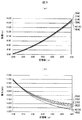
図3は、耐雷架空地線の弛度及び張力について示し、(a)は弛度特性を示す図、(b)は張力特性を示す図である。なお、弛度及び張力については20℃の温度条件下での特性について示している。 FIG. 3 shows the sag and tension of the lightning-resistant overhead ground wire, where (a) shows the sag characteristic and (b) shows the tension characteristic. In addition, about the looseness and tension | tensile_strength, it has shown about the characteristic under the temperature conditions of 20 degreeC.
図3(a)及び(b)に示されるように、従来例の標準AC150mm2と図1に示す実施例7の耐雷架空地線(40AC)1は、弛度及び張力ともに同等の特性を有する。そのため、架空地線の張り替えに際しても既存の布設工法での施工が可能で、標準の付属品の使用も可能である。 As shown in FIGS. 3A and 3B, the standard AC 150 mm 2 of the conventional example and the lightning-resistant overhead ground wire (40AC) 1 of Example 7 shown in FIG. 1 have the same characteristics in both sag and tension. . For this reason, the existing laying method can be used to replace the overhead ground wire, and standard accessories can be used.
図4は、耐雷架空地線に対するアーク試験時の電荷量とより線破断荷重について示し、(a)は実施例1、4、及び7の耐雷架空地線について示す図、(b)は標準AC150mm2について示す図である。なお、電荷量については基準張力を30.4kNとしたときの安全率2.5(=76kN)を確保できる値を示している。 FIG. 4 shows the charge amount and twisted wire breaking load during an arc test for a lightning-resistant overhead ground wire, (a) is a diagram showing the lightning-resistant overhead ground wires of Examples 1, 4, and 7, and (b) is a standard AC 150 mm. it is a diagram showing a 2. The charge amount is a value that can secure a safety factor of 2.5 (= 76 kN) when the reference tension is 30.4 kN.
電荷量については、図4(a)に示すように、実施例1で505C、実施例4で428C、実施例7で301Cを示している。一方、図4(b)に示す従来例の標準AC150mm2は195Cであることから、実施例1、4、及び7の耐雷架空地線では夏季雷、冬季雷の落雷に対しても素線断線を生じにくい構造が得られていることがわかる。 As shown in FIG. 4A, the charge amount is 505C in the first embodiment, 428C in the fourth embodiment, and 301C in the seventh embodiment. On the other hand, since the standard AC 150 mm 2 of the conventional example shown in FIG. 4B is 195C, the wire breakage in the lightning-resistant overhead ground wires of Examples 1, 4, and 7 even for lightning strikes in summer and winter lightning It can be seen that a structure is obtained that is less likely to cause stagnation.
また、耐熱試験として、各実施例及び従来例の耐雷架空地線について、電線長を約3mとし、13.5%UTS(ultimate tensile strength)でEDS(Every Day Stress)の条件で定張力装置に架線した。そして瞬時許容電流400℃まで電線温度を上昇させた後、通電を停止して室温まで冷却して熱履歴を確認した。 In addition, as a heat resistance test, for each lightning proof overhead ground wire of each example and the conventional example, the wire length is about 3 m, and the constant tension device is used under the condition of EDS (Every Day Stress) at 13.5% UTS (ultimate tensile strength). It was overlaid. And after raising electric wire temperature to instantaneous allowable current 400 degreeC, electricity supply was stopped and it cooled to room temperature, and confirmed the heat history.
耐熱試験後、内層40ACタイプ、内層30ACタイプとも、耐雷架空地線の外観に笑い等の異常は確認されなかった。実施例7の内層40ACタイプは外層の素線40ACと同一の線種であり、線膨張係数も15.5×10⁻⁶/℃で同一であること、また、内層30ACタイプの線膨張係数も15.0×10−6/℃で40ACとほぼ同等の値であることから、熱応力による影響は小さいものと考えられる。 After the heat test, no abnormalities such as laughter were observed in the appearance of the lightning-resistant overhead ground wire in both the inner layer 40AC type and the inner layer 30AC type. The inner layer 40AC type of Example 7 is the same line type as the outer layer strand 40AC, the linear expansion coefficient is the same at 15.5 × 10 −6 / ° C., and the linear expansion coefficient of the inner layer 30AC type is also the same. Since it is a value substantially equal to 40 AC at 15.0 × 10 −6 / ° C., it is considered that the influence of thermal stress is small.
また、振動疲労試験として、各実施例及び従来例の耐雷架空地線について、EDSの厳しい側の条件である20%UTSで架線して振動疲労試験を行った。振動疲労試験は電線表面にひずみゲージを貼り付け、発生ひずみ量を±100μst(100×10−6)に設定し、加振周波数20Hzで107回加振することにより行った。振動疲労試験後、各実施例の耐雷架空地線では、素線のアルミニウム被覆部に割れ等の異常は認められず、健全な状態であることを確認した。
In addition, as a vibration fatigue test, the vibration fatigue test was performed on the lightning-resistant overhead ground wires of each of the examples and the conventional examples by laying the wires at 20% UTS, which is a severe condition of EDS. Vibration fatigue test paste strain gauge on the cable surface, to set the generated distortion amount ± 100μst (100 × 10 -6) , was conducted by vibrating 10 7 times at
また、金車通過試験として、内層40ACタイプ、内層30ACタイプの耐雷架空地線について実規模延線を想定した金車通過試験(金車径φ300mm、水平角30°、抱角60°、往復20回)を実施した。金車試験時に、各実施例の耐雷架空地線とも各部で笑いは発生しなかった。また、金車通過時のピッチ、電線外径を測定した結果、20回通過後も電線外径、ピッチに変化は認められなかった。試験後、耐雷架空地線を解体してニッキング率を調査した結果、最大ニッキング率は規格値の10%以下であり、実用上問題ないことを確認した。
In addition, as a gold wheel passage test, an inner layer 40AC type and inner layer 30AC type lightning-proof overhead ground wire assuming a full-scale extension wire test (gold wheel diameter φ300 mm, horizontal angle 30 °, holding
また、付属品試験として、標準AC150mm2用の標準品である圧縮クランプ、直線スリーブを使用して各実施例の耐雷架空地線について線状掌握力試験を実施した。その結果、内層40ACタイプ、内層30ACタイプの耐雷架空地線で規格値である95%UTS以上の値を示し、標準付属品の適用が可能であることを確認した。上記試験などの結果から、本実施例の耐雷架空地線は優れた電線強度を有するものである。 In addition, as an accessory test, a linear gripping force test was conducted on the lightning-resistant overhead ground wire of each example using a compression clamp and a linear sleeve, which are standard products for standard AC 150 mm 2 . As a result, the inner layer 40AC type and the inner layer 30AC type lightning-resistant overhead ground wire showed a standard value of 95% UTS or more, and it was confirmed that standard accessories could be applied. From the results of the above test and the like, the lightning-resistant overhead ground wire of the present example has excellent electric wire strength.
1…耐雷架空地線、10、20…素線、11、21…芯材、12、22…アルミニウム被覆材、100…内層、200…外層
DESCRIPTION OF
Claims (3)
前記第2の素線は、外径が3.8mmから4.2mmで形成されることを特徴とする請求項1に記載の耐雷架空地線。 The first strand is formed with an outer diameter of 2.53 mm to 2.8 mm,
2. The lightning-resistant overhead ground wire according to claim 1, wherein the second strand has an outer diameter of 3.8 mm to 4.2 mm.
Priority Applications (1)
| Application Number | Priority Date | Filing Date | Title |
|---|---|---|---|
| JP2008177300A JP5255931B2 (en) | 2008-07-07 | 2008-07-07 | Lightning-resistant overhead ground wire |
Applications Claiming Priority (1)
| Application Number | Priority Date | Filing Date | Title |
|---|---|---|---|
| JP2008177300A JP5255931B2 (en) | 2008-07-07 | 2008-07-07 | Lightning-resistant overhead ground wire |
Publications (2)
| Publication Number | Publication Date |
|---|---|
| JP2010015946A true JP2010015946A (en) | 2010-01-21 |
| JP5255931B2 JP5255931B2 (en) | 2013-08-07 |
Family
ID=41701859
Family Applications (1)
| Application Number | Title | Priority Date | Filing Date |
|---|---|---|---|
| JP2008177300A Active JP5255931B2 (en) | 2008-07-07 | 2008-07-07 | Lightning-resistant overhead ground wire |
Country Status (1)
| Country | Link |
|---|---|
| JP (1) | JP5255931B2 (en) |
Cited By (1)
| Publication number | Priority date | Publication date | Assignee | Title |
|---|---|---|---|---|
| JP2017009507A (en) * | 2015-06-24 | 2017-01-12 | 東京電力ホールディングス株式会社 | Lightning damage determination device and lightning damage determination system |
Citations (2)
| Publication number | Priority date | Publication date | Assignee | Title |
|---|---|---|---|---|
| JPH05297054A (en) * | 1992-04-20 | 1993-11-12 | Furukawa Electric Co Ltd:The | Method and apparatus for detecting position of lightning strike |
| JP2008251267A (en) * | 2007-03-29 | 2008-10-16 | Tokyo Electric Power Co Inc:The | Thunderbolt resistant aerial ground wire |
-
2008
- 2008-07-07 JP JP2008177300A patent/JP5255931B2/en active Active
Patent Citations (2)
| Publication number | Priority date | Publication date | Assignee | Title |
|---|---|---|---|---|
| JPH05297054A (en) * | 1992-04-20 | 1993-11-12 | Furukawa Electric Co Ltd:The | Method and apparatus for detecting position of lightning strike |
| JP2008251267A (en) * | 2007-03-29 | 2008-10-16 | Tokyo Electric Power Co Inc:The | Thunderbolt resistant aerial ground wire |
Cited By (1)
| Publication number | Priority date | Publication date | Assignee | Title |
|---|---|---|---|---|
| JP2017009507A (en) * | 2015-06-24 | 2017-01-12 | 東京電力ホールディングス株式会社 | Lightning damage determination device and lightning damage determination system |
Also Published As
| Publication number | Publication date |
|---|---|
| JP5255931B2 (en) | 2013-08-07 |
Similar Documents
| Publication | Publication Date | Title |
|---|---|---|
| RU161777U1 (en) | RAILWAY CONTACT NETWORK ROPE | |
| JP4550218B2 (en) | Optical fiber composite ground wire | |
| AU2012204300A1 (en) | Aluminum alloy conductor composite reinforced for high voltage overhead power lines | |
| US9508466B2 (en) | High-frequency electric wire, manufacturing method thereof, and wire harness | |
| WO2012060737A3 (en) | Overhead ground wire with optical communication cable | |
| WO2012128664A1 (en) | Method for manufacturing a high-temperature conductor for an overhead power transmission line, and conductor produced by said method | |
| RU113061U1 (en) | Lightning protection cable for air transmission lines | |
| JP5255931B2 (en) | Lightning-resistant overhead ground wire | |
| US20170133117A1 (en) | Electric power transmission cable with composite cores | |
| CN109616976A (en) | A kind of preformed ground wire carrying out safety backup wire clamp | |
| JP4938403B2 (en) | Fiber composite wire conductor and insulated wire | |
| RU93178U1 (en) | DARK-PROTECTED CABLE (OPTIONS) | |
| RU171205U1 (en) | Bearing reinforced cable of the contact network of the railway | |
| JP2008251267A (en) | Thunderbolt resistant aerial ground wire | |
| RU119514U1 (en) | UNINSULATED REINFORCED WIRE FOR ELECTRIC TRANSMISSION AIR LINES (OPTIONS) | |
| RU2706957C1 (en) | Non-insulated steel-aluminum high-temperature high-strength wire | |
| CA2996086C (en) | Conductor for a power transmission cable and a process for the production of the conductor | |
| CN102969087A (en) | Manufacturing method for interlocked armored aluminum alloy flat cable | |
| RU127239U1 (en) | DARK-PROTECTED CABLE (OPTIONS) | |
| RU2361304C1 (en) | Overhead ground wire cable | |
| RU142762U1 (en) | UNINSULATED STEEL ALUMINUM WIRE HIGH STRENGTH, HIGH TEMPERATURE FOR ELECTRIC TRANSMISSION AIR LINES (OPTIONS) | |
| US9941028B2 (en) | Electrical conductor for aeronautical applications | |
| RU78362U1 (en) | Lightning protection cable | |
| EP2410534A1 (en) | Cord for high voltage overhead electrical lines, with high thermal limit and with 3 load-bearing cables | |
| RU114553U1 (en) | DARK-PROTECTED CABLE FOR ELECTRIC TRANSMISSION AIR LINES |
Legal Events
| Date | Code | Title | Description |
|---|---|---|---|
| A621 | Written request for application examination |
Free format text: JAPANESE INTERMEDIATE CODE: A621 Effective date: 20110329 |
|
| A131 | Notification of reasons for refusal |
Free format text: JAPANESE INTERMEDIATE CODE: A131 Effective date: 20130212 |
|
| A521 | Request for written amendment filed |
Free format text: JAPANESE INTERMEDIATE CODE: A523 Effective date: 20130321 |
|
| TRDD | Decision of grant or rejection written | ||
| A01 | Written decision to grant a patent or to grant a registration (utility model) |
Free format text: JAPANESE INTERMEDIATE CODE: A01 Effective date: 20130416 |
|
| A61 | First payment of annual fees (during grant procedure) |
Free format text: JAPANESE INTERMEDIATE CODE: A61 Effective date: 20130422 |
|
| R150 | Certificate of patent or registration of utility model |
Ref document number: 5255931 Country of ref document: JP Free format text: JAPANESE INTERMEDIATE CODE: R150 Free format text: JAPANESE INTERMEDIATE CODE: R150 |
|
| FPAY | Renewal fee payment (event date is renewal date of database) |
Free format text: PAYMENT UNTIL: 20160426 Year of fee payment: 3 |
|
| S531 | Written request for registration of change of domicile |
Free format text: JAPANESE INTERMEDIATE CODE: R313531 |
|
| R350 | Written notification of registration of transfer |
Free format text: JAPANESE INTERMEDIATE CODE: R350 |
|
| S111 | Request for change of ownership or part of ownership |
Free format text: JAPANESE INTERMEDIATE CODE: R313115 |
|
| R350 | Written notification of registration of transfer |
Free format text: JAPANESE INTERMEDIATE CODE: R350 |
|
| R250 | Receipt of annual fees |
Free format text: JAPANESE INTERMEDIATE CODE: R250 |
|
| S533 | Written request for registration of change of name |
Free format text: JAPANESE INTERMEDIATE CODE: R313533 |
|
| R350 | Written notification of registration of transfer |
Free format text: JAPANESE INTERMEDIATE CODE: R350 |
|
| R250 | Receipt of annual fees |
Free format text: JAPANESE INTERMEDIATE CODE: R250 |
|
| R250 | Receipt of annual fees |
Free format text: JAPANESE INTERMEDIATE CODE: R250 |
|
| R250 | Receipt of annual fees |
Free format text: JAPANESE INTERMEDIATE CODE: R250 |
|
| R250 | Receipt of annual fees |
Free format text: JAPANESE INTERMEDIATE CODE: R250 |
|
| R250 | Receipt of annual fees |
Free format text: JAPANESE INTERMEDIATE CODE: R250 |
|
| R250 | Receipt of annual fees |
Free format text: JAPANESE INTERMEDIATE CODE: R250 |
|
| R250 | Receipt of annual fees |
Free format text: JAPANESE INTERMEDIATE CODE: R250 |
|
| R250 | Receipt of annual fees |
Free format text: JAPANESE INTERMEDIATE CODE: R250 |