JP2010014617A - ピン型ロードセル - Google Patents
ピン型ロードセル Download PDFInfo
- Publication number
- JP2010014617A JP2010014617A JP2008176140A JP2008176140A JP2010014617A JP 2010014617 A JP2010014617 A JP 2010014617A JP 2008176140 A JP2008176140 A JP 2008176140A JP 2008176140 A JP2008176140 A JP 2008176140A JP 2010014617 A JP2010014617 A JP 2010014617A
- Authority
- JP
- Japan
- Prior art keywords
- pin
- sensor
- load cell
- type load
- strain measurement
- Prior art date
- Legal status (The legal status is an assumption and is not a legal conclusion. Google has not performed a legal analysis and makes no representation as to the accuracy of the status listed.)
- Granted
Links
- 229920005989 resin Polymers 0.000 claims abstract description 32
- 239000011347 resin Substances 0.000 claims abstract description 32
- 230000002093 peripheral effect Effects 0.000 claims abstract description 6
- 238000005259 measurement Methods 0.000 claims description 42
- 230000035945 sensitivity Effects 0.000 claims description 14
- 230000035515 penetration Effects 0.000 claims description 13
- 238000011088 calibration curve Methods 0.000 claims description 12
- 238000007789 sealing Methods 0.000 claims description 8
- 230000007423 decrease Effects 0.000 claims description 7
- 239000004065 semiconductor Substances 0.000 claims description 4
- 238000005070 sampling Methods 0.000 abstract description 7
- 238000000034 method Methods 0.000 description 13
- 230000004048 modification Effects 0.000 description 8
- 238000012986 modification Methods 0.000 description 8
- 239000000853 adhesive Substances 0.000 description 4
- 230000001070 adhesive effect Effects 0.000 description 3
- 238000010586 diagram Methods 0.000 description 3
- XLYOFNOQVPJJNP-UHFFFAOYSA-N water Substances O XLYOFNOQVPJJNP-UHFFFAOYSA-N 0.000 description 3
- 238000009412 basement excavation Methods 0.000 description 2
- 230000003247 decreasing effect Effects 0.000 description 2
- 230000000694 effects Effects 0.000 description 2
- 239000012535 impurity Substances 0.000 description 2
- 230000009467 reduction Effects 0.000 description 2
- 238000005452 bending Methods 0.000 description 1
- 230000008901 benefit Effects 0.000 description 1
- 230000008859 change Effects 0.000 description 1
- 238000001514 detection method Methods 0.000 description 1
- 238000009792 diffusion process Methods 0.000 description 1
- 230000009545 invasion Effects 0.000 description 1
- 238000004519 manufacturing process Methods 0.000 description 1
- 239000002184 metal Substances 0.000 description 1
- 238000012544 monitoring process Methods 0.000 description 1
- 229910021421 monocrystalline silicon Inorganic materials 0.000 description 1
- 230000000149 penetrating effect Effects 0.000 description 1
- 238000010008 shearing Methods 0.000 description 1
- 229920002050 silicone resin Polymers 0.000 description 1
- 230000009466 transformation Effects 0.000 description 1
- 238000003466 welding Methods 0.000 description 1
Images


Landscapes
- Measurement Of Force In General (AREA)
Abstract
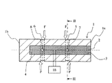
【解決手段】ピン1と、ピン1の端面1aからピン1の軸方向に設けられた穴3と、ピン1の周方向に沿ってピン1の外周面上に設けられたピン溝5,6と、ピン溝5,6の幅内に収まるようにピン1の軸方向の異なる位置にそれぞれ配置され、穴3の内部に固定されたセンサ7,8と、穴3の内部に充填された樹脂4と、センサ7の出力値とセンサ8の出力値をサンプリングし、その出力値の差がセンサ7の寿命を判定するために設定した閾値を超えたことを報知する報知装置18とを備える。
【選択図】図1
Description
1a 端面
1b 端面
2 開口部
3 穴(ピン穴)
4 樹脂
5 ピン溝
5B ピン溝
6 ピン溝
6B ピン溝
7 センサ
8 センサ
11 センサ
12 センサ
13 棒材
14 センサ群
15 センサ
16 センサ
18 報知装置
19 開口部
22 封止部材
28 第1樹脂
29 第2樹脂
30 貫通孔
31 センサ群
32 センサ群
Claims (12)
- ピンと、
このピンの一方の端面から前記ピンの軸方向に設けられた穴と、
この穴の内部に固定され、前記ピンの軸方向の異なる位置に配置された複数のひずみ測定センサと、
この複数のひずみ測定センサが、前記ピンの周方向に沿って前記ピンの外周面上に設けられた溝の幅内に収まるように形成された1または複数のピン溝と、
前記穴の内部に充填された樹脂と、
前記複数のひずみ測定センサのうち前記ピンの一方の端面に最も近いものの出力値、及びその他のひずみ測定センサのうち少なくとも1つの出力値をサンプリングし、そのサンプリングした前記ピンの一方の端面に最も近いひずみ測定センサの出力値と前記その他のひずみ測定センサの出力値の差が、前記ピンの一方の端面に最も近いひずみ測定センサの寿命を判定するために設定した閾値を超えたことを報知する報知装置とを備えることを特徴とするピン型ロードセル。 - 請求項1記載のピン型ロードセルにおいて、
前記ピン型ロードセルには均等な荷重が作用しており、
前記複数のひずみ測定センサは、前記ピン溝の幅内に1つずつ収まるように配置されていることを特徴とするピン型ロードセル。 - 請求項1又は2記載のピン型ロードセルにおいて、
前記ピン型ロードセルには均等な荷重が作用しており、
前記複数のひずみ測定センサは、前記ピンの一方の端面から最も近い第1ひずみ測定センサと、及び前記ピンの他方の端面から最も近い第2ひずみ測定センサとによって構成され、
前記ピンの一方の端面から前記第1ひずみ測定センサまでの距離と、前記ピンの他方の端面から前記第2ひずみ測定センサまでの距離とは等しく設定されており、
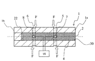
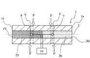
前記穴は、前記ピンの他方の端面に向かって設けられた貫通孔であり、
前記樹脂は、前記貫通孔の前記第1ひずみ測定センサ側に充填された第1樹脂と、前記貫通孔の前記第2ひずみ測定センサ側に充填され、前記第1樹脂より相対的に水分侵入速度が遅い第2樹脂とによって構成されていることを特徴とするピン型ロードセル。 - 請求項1記載のピン型ロードセルにおいて、
前記ピンの一方の端面に最も近い前記ピン溝の幅内に、前記複数のひずみ測定センサのうちの2以上のひずみ測定センサを設けたことを特徴とするピン型ロードセル。 - 請求項1から4いずれかに記載のピン型ロードセルにおいて、
前記報知装置は、前記出力差が前記閾値を超えるまでに要した時間に基づいて水分侵入速度を算出し、寿命に達していない残りのひずみ測定センサの寿命を予測することを特徴とするピン型ロードセル。 - 請求項1から4いずれかに記載のピン型ロードセルにおいて、
前記報知装置は、前記ピンの軸方向に沿って前記穴の内部に一列に配列された複数のひずみ測定センサの出力値が低下するまでに要する時間を測定して事前に求めた校正曲線に基づいて、寿命に達していない残りのひずみ測定センサの寿命を予測することを特徴とするピン型ロードセル。 - 請求項1から6いずれかに記載のピン型ロードセルにおいて、
前記ひずみ測定センサは、前記ピンの内壁面に固定されていることを特徴とするピン型ロードセル。 - 請求項1から6いずれかに記載のピン型ロードセルにおいて、
前記ひずみ測定センサは、前記樹脂によって前記穴の内部に固定された棒材に取り付けられていることを特徴とするピン型ロードセル - 請求項1から8いずれかに記載のピン型ロードセルにおいて、
前記ひずみ測定センサは、その感度方向が前記ピンの軸方向に対して45度傾いた姿勢で固定されていることを特徴とするピン型ロードセル。 - 請求項1から9いずれかに記載のピン型ロードセルにおいて、
前記ひずみ測定センサは、4個のひずみ測定センサから構成されるセンサ群であり、
このセンサ群を構成する前記4個のひずみ測定センサは、前記ピンの同一横断面上において均等配置されるように、前記ピンの内壁面上に固定されていることを特徴とするピン型ロードセル。 - 請求項1から10いずれかに記載のピン型ロードセルにおいて、
前記ひずみ測定センサは、ひずみゲージ又は半導体ひずみセンサであることを特徴とするピン型ロードセル。 - 請求項1から2、又は請求項4から11のいずれかに記載のピン型ロードセルにおいて、
前記穴は、前記ピンの軸方向に設けた貫通孔の一端に封止部材を取り付けて設けられていることを特徴とするピン型ロードセル。
Priority Applications (1)
| Application Number | Priority Date | Filing Date | Title |
|---|---|---|---|
| JP2008176140A JP5254685B2 (ja) | 2008-07-04 | 2008-07-04 | ピン型ロードセル |
Applications Claiming Priority (1)
| Application Number | Priority Date | Filing Date | Title |
|---|---|---|---|
| JP2008176140A JP5254685B2 (ja) | 2008-07-04 | 2008-07-04 | ピン型ロードセル |
Publications (3)
| Publication Number | Publication Date |
|---|---|
| JP2010014617A true JP2010014617A (ja) | 2010-01-21 |
| JP2010014617A5 JP2010014617A5 (ja) | 2010-09-09 |
| JP5254685B2 JP5254685B2 (ja) | 2013-08-07 |
Family
ID=41700856
Family Applications (1)
| Application Number | Title | Priority Date | Filing Date |
|---|---|---|---|
| JP2008176140A Expired - Fee Related JP5254685B2 (ja) | 2008-07-04 | 2008-07-04 | ピン型ロードセル |
Country Status (1)
| Country | Link |
|---|---|
| JP (1) | JP5254685B2 (ja) |
Cited By (3)
| Publication number | Priority date | Publication date | Assignee | Title |
|---|---|---|---|---|
| JP2019215270A (ja) * | 2018-06-13 | 2019-12-19 | アルプスアルパイン株式会社 | 踏力検出装置 |
| JP2021116547A (ja) * | 2020-01-23 | 2021-08-10 | 株式会社大林組 | 油圧ショベル |
| JP2024009435A (ja) * | 2022-07-11 | 2024-01-23 | 株式会社グローセル | 対象物状態解析システム、対象物状態解析方法、およびプログラム |
Families Citing this family (1)
| Publication number | Priority date | Publication date | Assignee | Title |
|---|---|---|---|---|
| JP6473240B2 (ja) | 2016-03-30 | 2019-02-20 | 日立建機株式会社 | 運搬用車両 |
Citations (6)
| Publication number | Priority date | Publication date | Assignee | Title |
|---|---|---|---|---|
| JPS5540954A (en) * | 1978-09-18 | 1980-03-22 | Kawasaki Steel Corp | Load cell failure detection method and its unit |
| JPS6055237A (ja) * | 1983-09-06 | 1985-03-30 | Yotaro Hatamura | 荷重検出装置 |
| JPS61145427A (ja) * | 1984-12-19 | 1986-07-03 | Hitachi Constr Mach Co Ltd | 荷重検出装置 |
| JPH05264375A (ja) * | 1992-03-23 | 1993-10-12 | Yamato Scale Co Ltd | 力または荷重センサの故障診断装置及びその自己復帰装置 |
| JPH08201192A (ja) * | 1995-01-25 | 1996-08-09 | Kyowa Electron Instr Co Ltd | ピン型荷重変換器 |
| JPH10227684A (ja) * | 1997-02-12 | 1998-08-25 | Hitachi Constr Mach Co Ltd | 掘削機の荷重測定装置 |
-
2008
- 2008-07-04 JP JP2008176140A patent/JP5254685B2/ja not_active Expired - Fee Related
Patent Citations (6)
| Publication number | Priority date | Publication date | Assignee | Title |
|---|---|---|---|---|
| JPS5540954A (en) * | 1978-09-18 | 1980-03-22 | Kawasaki Steel Corp | Load cell failure detection method and its unit |
| JPS6055237A (ja) * | 1983-09-06 | 1985-03-30 | Yotaro Hatamura | 荷重検出装置 |
| JPS61145427A (ja) * | 1984-12-19 | 1986-07-03 | Hitachi Constr Mach Co Ltd | 荷重検出装置 |
| JPH05264375A (ja) * | 1992-03-23 | 1993-10-12 | Yamato Scale Co Ltd | 力または荷重センサの故障診断装置及びその自己復帰装置 |
| JPH08201192A (ja) * | 1995-01-25 | 1996-08-09 | Kyowa Electron Instr Co Ltd | ピン型荷重変換器 |
| JPH10227684A (ja) * | 1997-02-12 | 1998-08-25 | Hitachi Constr Mach Co Ltd | 掘削機の荷重測定装置 |
Cited By (5)
| Publication number | Priority date | Publication date | Assignee | Title |
|---|---|---|---|---|
| JP2019215270A (ja) * | 2018-06-13 | 2019-12-19 | アルプスアルパイン株式会社 | 踏力検出装置 |
| JP2021116547A (ja) * | 2020-01-23 | 2021-08-10 | 株式会社大林組 | 油圧ショベル |
| JP7484180B2 (ja) | 2020-01-23 | 2024-05-16 | 株式会社大林組 | 油圧ショベル |
| JP2024009435A (ja) * | 2022-07-11 | 2024-01-23 | 株式会社グローセル | 対象物状態解析システム、対象物状態解析方法、およびプログラム |
| JP7777045B2 (ja) | 2022-07-11 | 2025-11-27 | 株式会社マクニカ | 対象物状態解析システム、対象物状態解析方法、およびプログラム |
Also Published As
| Publication number | Publication date |
|---|---|
| JP5254685B2 (ja) | 2013-08-07 |
Similar Documents
| Publication | Publication Date | Title |
|---|---|---|
| JP4528810B2 (ja) | 荷重センサおよび荷重センサの製造方法 | |
| JP5215878B2 (ja) | 作業機械及びピン型ロードセル | |
| US10488281B2 (en) | Axial force pressure transducer | |
| JP5254685B2 (ja) | ピン型ロードセル | |
| ES2947220T3 (es) | Métodos y sistemas para la medición de la corrosión en el sitio | |
| US8869633B2 (en) | Bearing device having a sensor for measuring the vertical bearing force of a rotating shaft | |
| US20130340537A1 (en) | Force sensor including sensor plate with local differences in stiffness | |
| EP3312556A1 (en) | Mechanical strain amplifying transducer | |
| US8479582B2 (en) | Pressure transmitter | |
| EP2081007B1 (en) | Load measuring pin | |
| JP2021045845A5 (ja) | ||
| KR100878545B1 (ko) | 베어링의 하중 감지 및 베어링의 상태 감시를 조합한 센서어셈블리 및 센서 시스템 | |
| US20100108510A1 (en) | Measuring device for monitoring the corrosion of a steel reinforcement | |
| EP3532816B1 (en) | Strain gauge | |
| JP5184052B2 (ja) | 燃焼圧センサ | |
| JP5149081B2 (ja) | ひずみ量測定機能付き締結具 | |
| JP2008281388A (ja) | 軸受荷重測定装置付き軸受及びその軸受の荷重測定方法 | |
| JP2010014617A5 (ja) | ||
| JP4762620B2 (ja) | 測定装置及び流速測定システム | |
| US8117003B2 (en) | Method of monitoring an electrochemical half-cell | |
| CN206348218U (zh) | 一种埋入式混凝土剪应力传感器 | |
| KR20070039705A (ko) | 강선을 이용한 앵커의 축력측정용 모노로드셀 및 그앵커구조 | |
| KR200405462Y1 (ko) | 강선을 이용한 앵커의 축력측정용 모노로드셀 및 그앵커구조 | |
| US20240151598A1 (en) | Load cell | |
| KR100965386B1 (ko) | 미세힘 측정센서 |
Legal Events
| Date | Code | Title | Description |
|---|---|---|---|
| A521 | Request for written amendment filed |
Free format text: JAPANESE INTERMEDIATE CODE: A523 Effective date: 20100723 |
|
| A621 | Written request for application examination |
Free format text: JAPANESE INTERMEDIATE CODE: A621 Effective date: 20100723 |
|
| A977 | Report on retrieval |
Free format text: JAPANESE INTERMEDIATE CODE: A971007 Effective date: 20120615 |
|
| A131 | Notification of reasons for refusal |
Free format text: JAPANESE INTERMEDIATE CODE: A131 Effective date: 20120626 |
|
| A521 | Request for written amendment filed |
Free format text: JAPANESE INTERMEDIATE CODE: A523 Effective date: 20120810 |
|
| TRDD | Decision of grant or rejection written | ||
| A01 | Written decision to grant a patent or to grant a registration (utility model) |
Free format text: JAPANESE INTERMEDIATE CODE: A01 Effective date: 20130326 |
|
| A61 | First payment of annual fees (during grant procedure) |
Free format text: JAPANESE INTERMEDIATE CODE: A61 Effective date: 20130418 |
|
| R150 | Certificate of patent or registration of utility model |
Ref document number: 5254685 Country of ref document: JP Free format text: JAPANESE INTERMEDIATE CODE: R150 Free format text: JAPANESE INTERMEDIATE CODE: R150 |
|
| FPAY | Renewal fee payment (event date is renewal date of database) |
Free format text: PAYMENT UNTIL: 20160426 Year of fee payment: 3 |
|
| LAPS | Cancellation because of no payment of annual fees |