JP2010011641A - Rotor of induction motor and method of manufacturing the same - Google Patents
Rotor of induction motor and method of manufacturing the same Download PDFInfo
- Publication number
- JP2010011641A JP2010011641A JP2008168096A JP2008168096A JP2010011641A JP 2010011641 A JP2010011641 A JP 2010011641A JP 2008168096 A JP2008168096 A JP 2008168096A JP 2008168096 A JP2008168096 A JP 2008168096A JP 2010011641 A JP2010011641 A JP 2010011641A
- Authority
- JP
- Japan
- Prior art keywords
- laminated steel
- rotor
- die casting
- induction motor
- slot
- Prior art date
- Legal status (The legal status is an assumption and is not a legal conclusion. Google has not performed a legal analysis and makes no representation as to the accuracy of the status listed.)
- Granted
Links
Images


Abstract
Description
本発明は、耐腐食性を持たせた誘導電動機のロータ及びその製造方法に関する。 The present invention relates to an induction motor rotor having corrosion resistance and a method of manufacturing the same.
レーザーガス中に含まれるフッ素に対する耐腐食性を持たせた誘導電動機として、特許文献1には以下の記載がある。即ち、段落[0051]には「また、変位センサターゲット8c及び電磁石ターゲット8dには、回転によって生じる磁界変化によって渦電流損失が発生する。この渦電流損失を低減するため、通常は薄板を積層した構造をとる。しかしながら、積層した薄板の間にガス溜りができレーザガスを汚染したり、PBパーマロイを使用する場合に積層表面に均一で密着性の高いNiメッキが施せない等の問題が生じる…」と記載され、また、段落[0058]には「また、モータ12のモータロータ12bは、積層したけい素鋼板とアルミニウムの複合材からなるので表面に耐腐食処理として好適なNiメッキを密着性良く、均一に施工できない。よって、モータロータ12bの外周面にキャン50を取付け、側板51、51と溶接等により固着し、…」と記載されている。 As an induction motor having corrosion resistance against fluorine contained in laser gas, Patent Document 1 has the following description. That is, in paragraph [0051], “In the displacement sensor target 8c and the electromagnet target 8d, an eddy current loss occurs due to a magnetic field change caused by rotation. In order to reduce this eddy current loss, a thin plate is usually laminated. However, there is a problem that gas can accumulate between the laminated thin plates, contaminating the laser gas, and when using PB permalloy, it is impossible to apply Ni plating with uniform and high adhesion to the laminated surface ... " In paragraph [0058], “the motor rotor 12b of the motor 12 is made of a laminated silicon steel plate and aluminum composite material, so that the surface is coated with a suitable Ni plating as a corrosion-resistant treatment with good adhesion. Therefore, the can 50 is attached to the outer peripheral surface of the motor rotor 12b and fixed to the side plates 51 and 51 by welding or the like. , It has been described as ... ".
特許文献2には以下の記載がある。即ち、段落[0007]には、「…ロータは電磁鋼板とアルミ合金等の複合材で構成されるため、移送気体が腐食性を有するとモータロータを腐食することになる。これを防止するため、ロータ表面にも耐腐食性を有するコーティングを行なうか、もしくはキャンで被覆する必要がある。しかしながら、電磁鋼板やアルミ合金等の複合材へのコーティングは信頼性が乏しく、コーティング膜の剥離が生じ易い等の問題もある。更に又、キャンは、ロータとステータ間のギャップを広げるため、効率が悪くなるという問題がある。」と記載されている。
特許文献3には以下の記載がある。即ち、段落[0028]には、「…回転子2のアルミニウム製エンドリング1の部分に表面処理層9(例えば、アルマイト処理,ほうろう処理,無電解ニッケルメッキ処理,クロメート処理,亜鉛メッキ処理,樹脂の塗布処理)を設けているので、アルミニウム部分の腐食を促進する燐系耐摩耗剤を含む冷凍機油と冷媒3が、アルミニウム部分に直接接触しないように構成したため、電動要素の腐食が発生しない電動圧縮機を提供できる。…」と記載されている。
特許文献1に記載される通り、積層鋼板によるロータの積層表面は凹凸がある為、直接メッキを施そうとする場合には、密着性良く耐腐食性メッキを施すことが困難である。
また、特許文献1,2に記載される通り、耐腐食性ロータを製作する方法として、ロータを耐腐食性材料による別部品から成るキャンで覆う等の方法もあるが、この方法では作業の手間と時間がかかる。
As described in Patent Document 1, since the laminated surface of the rotor made of laminated steel plates has irregularities, it is difficult to apply corrosion-resistant plating with good adhesion when direct plating is desired.
Further, as described in
なお、特許文献3では、ロータ(回転子)のエンドリングの部分に、表面処理層を形成しているが、ロータの外周面には表面処理層は形成されていない。
本発明は、上記従来技術に鑑みてなされたものであり、耐腐食性を持たせた誘導電動機のロータ及びその製造方法を提供するにある。
In
The present invention has been made in view of the above prior art, and provides a rotor for an induction motor having corrosion resistance and a method for manufacturing the same.
上記課題を解決する本発明の請求項1に係る誘導電動機のロータは、円形状鋼板を積層して形成され積層方向に貫通するスロットを有する円筒状の積層鋼板と、前記スロット内に充填される2次導体と、前記積層鋼板の両端面に配置され前記2次導体に接続するエンドリングとからなる誘導電動機のロータにおいて、前記スロット内に前記2次導体としてアルミニウムをダイキャストにより形成すると共に前記積層鋼板の両端面に前記エンドリングとしてアルミニウムをダイキャストにより形成する際に、前記積層鋼板の外周面に円筒状薄膜をダイキャストにより形成してなることを特徴とする。 A rotor of an induction motor according to claim 1 of the present invention that solves the above-mentioned problem is formed by laminating circular steel plates and having a cylindrical laminated steel plate having slots penetrating in the laminating direction, and filling the slots. In an induction motor rotor comprising a secondary conductor and end rings arranged on both end faces of the laminated steel plate and connected to the secondary conductor, aluminum is formed as the secondary conductor in the slot by die casting, and When aluminum is formed as the end ring by die casting on both end faces of the laminated steel sheet, a cylindrical thin film is formed by die casting on the outer peripheral surface of the laminated steel sheet.
上記課題を解決する本発明の請求項2に係る誘導電動機のロータは、請求項1において、前記薄膜表面及び前記エンドリング表面には、耐腐食性メッキが施されることを特徴とする。
The rotor of an induction motor according to
上記課題を解決する本発明の請求項3に係る誘導電動機のロータは、請求項1又は2において、前記積層鋼板の両端面と前記エンドリングの間には、前記2次導体と前記エンドリングとを接続する貫通孔を有する耐腐食性端板が介装されることを特徴とする。 The rotor of an induction motor according to a third aspect of the present invention for solving the above-mentioned problems is the rotor according to the first or second aspect, wherein the secondary conductor and the end ring are disposed between both end faces of the laminated steel plate and the end ring. A corrosion-resistant end plate having a through hole connecting the two is interposed.
上記課題を解決する本発明の請求項4に係る誘導電動機のロータは、請求項3において、前記端板の外周縁は、前記円筒状薄膜の外表面と面一となることを特徴とする。 A rotor of an induction motor according to a fourth aspect of the present invention for solving the above-mentioned problems is characterized in that, in the third aspect, the outer peripheral edge of the end plate is flush with the outer surface of the cylindrical thin film.
上記課題を解決する本発明の請求項5に係る誘導電動機のロータは、請求項3又は4において、前記スロットが前記積層鋼板の外周面に対して閉塞したクローズドスロットの場合には、前記エンドリングと前記円筒状薄膜とを接続する切欠部を前記端板外周に配置することを特徴とする。
The rotor of an induction motor according to claim 5 of the present invention that solves the above-described problem is the rotor according to
上記課題を解決する本発明の請求項6に係る誘導電動機のロータの製造方法は、円形状鋼板を積層して形成され積層方向に貫通するスロットを有する円筒状の積層鋼板と共に該積層鋼板よりも僅かに直径が大きな耐腐食性端板を前記積層鋼板の両端面に重ねてダイキャスト型中に収容し、前記端板と前記ダイキャスト型の間に形成される端部空隙に溶融アルミニウムを充填してエンドリングをダイキャストにより形成しつつ、前記端板に形成される貫通孔を通じて前記スロットに溶融アルミニウムを充填して2次導体をダイキャストにより形成しながら、前記積層鋼板の外周面、前記ダイキャスト型及び前記端板との間に形成される外周表面上隙間に溶融アルミニウムを充填して円筒状薄膜をダイキャストにより形成することを特徴とする。
The method for manufacturing a rotor of an induction motor according to
上記課題を解決する本発明の請求項7に係る誘導電動機のロータの製造方法は、請求項6において、前記スロットが前記積層鋼板の外周面に対して開放されたオープンスロットの場合は、当該オープンスロットを通じて前記外周表面上隙間に溶融アルミニウムを充填して前記円筒状薄膜をダイキャストにより形成することを特徴とする。
The method for manufacturing a rotor of an induction motor according to
上記課題を解決する本発明の請求項8に係る誘導電動機のロータの製造方法は、請求項6において、前記スロットが前記積層鋼板の外周面に対して閉塞したクローズドスロットの場合は、前記端部空隙と前記円周表面上隙間とを連結する切欠部を前記端板に配置し、当該切欠部を通じて、前記端部空隙から前記外周表面上隙間に溶融アルミニウムを充填して前記円筒状薄膜をダイキャストにより形成することを特徴とする。 The method for manufacturing a rotor of an induction motor according to an eighth aspect of the present invention that solves the above-described problems is the method according to the sixth aspect, wherein in the case of the closed slot closed with respect to the outer peripheral surface of the laminated steel sheet, the end portion A notch for connecting the gap and the gap on the circumferential surface is disposed on the end plate, and through the notch, the gap on the outer circumference surface is filled with molten aluminum from the edge gap to die the cylindrical thin film. It is formed by casting.
上記課題を解決する本発明の請求項9に係る誘導電動機のロータの製造方法は、請求項6,7又は8において、前記円筒状薄膜の表面をダイキャストにより形成した後に加工することを特徴とする。
The method for manufacturing a rotor of an induction motor according to
上記課題を解決する本発明の請求項10に係る誘導電動機のロータの製造方法は、請求項6,7又は8において、前記薄膜表面及び前記エンドリング表面に、耐腐食性メッキを施すことを特徴とすることを特徴とする。
The method for manufacturing a rotor of an induction motor according to
本発明においては、2次導体及びエンドリングをダイキャストにより形成する際に、積層鋼板の外周面に円筒状薄膜としてアルミニウムをダイキャストにより形成するので、ロータを別部品から成るキャンで覆う等の作業よりも簡単に耐腐食性を持ったロータを作業性良く製作することができる。
また、積層鋼板の外周面上の凹凸はアルミニウムよりなる円筒状薄膜により埋められ、円筒状薄膜の表面は平滑なため、その上に耐腐食性メッキを密着性良く施すことができる。
In the present invention, when the secondary conductor and the end ring are formed by die casting, aluminum is formed by die casting as a cylindrical thin film on the outer peripheral surface of the laminated steel plate, so that the rotor is covered with a can made of another component, etc. A rotor with corrosion resistance can be manufactured with good workability more easily than work.
Moreover, since the unevenness | corrugation on the outer peripheral surface of a laminated steel plate is filled with the cylindrical thin film which consists of aluminum, and the surface of a cylindrical thin film is smooth, corrosion-resistant plating can be performed on it with sufficient adhesiveness.
本発明を実施するための最良の形態として、以下に実施例1及び実施例2を示す。 Examples 1 and 2 are shown below as the best mode for carrying out the present invention.
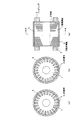
本発明の第1の実施例を図1〜図3を参照して説明する。図1は本実施例に係る誘導電動機のロータを示し、図2は本実施例に係る誘導電動機のロータに使用される端版を示し、図3は本実施例に係る誘導電動機のロータを製造する過程を示すものである。 A first embodiment of the present invention will be described with reference to FIGS. FIG. 1 shows the rotor of the induction motor according to this embodiment, FIG. 2 shows the end plate used for the rotor of the induction motor according to this embodiment, and FIG. 3 manufactures the rotor of the induction motor according to this embodiment. It shows the process.
図1に示すように、本実施例の誘導電動機のロータは、円形状鋼板を積層して形成される円筒状の積層鋼板1と、積層鋼板1の積層方向に貫通するスロット内に充填される2次導体(アルミバー)5と、積層鋼板1の両端面に端板2を介して配置されるエンドリング3とを備え、更に、積層鋼板1のスロット内に2次導体5としてアルミニウムをダイキャストにより形成すると共に積層鋼板1の両端面にエンドリング3としてアルミニウムをダイキャストにより形成する際に、積層鋼板1の外周面に円筒状薄膜4としてアルミニウムをダイキャストにより形成してなるものである。
As shown in FIG. 1, the rotor of the induction motor according to the present embodiment is filled in a cylindrical laminated steel plate 1 formed by laminating circular steel plates and a slot penetrating in the lamination direction of the laminated steel plates 1. A secondary conductor (aluminum bar) 5 and
積層鋼板1としては、図3(b)に示すように、外周面に対して開放されたオープンスロット1aを有する場合と、図3(c)に示すように、外周面に対して閉塞されたクローズドスロット1bを有する場合の二通りがある。
従って、積層鋼板1がオープンロット1aを有する場合は、図1(b)に示すように、オープンロット1aに充填される2次導体5と、積層鋼板1の外周面に形成される円筒状薄膜4とは連続してダイキャストにより形成されることになる。
また、積層鋼板1がクローズドスロット1bを有する場合は、図1(c)に示すように、クローズドスロット1bに充填される2次導体5と、積層鋼板1の外周面に形成される円筒状薄膜4とは不連続でダイキャストにより形成されることになる。
As shown in FIG. 3 (b), the laminated steel sheet 1 is closed with respect to the outer peripheral surface as shown in FIG. 3 (c) when it has an
Accordingly, when the laminated steel sheet 1 has the
When the laminated steel sheet 1 has the closed
端板2は、耐腐食性材料(例えばSUS316)からなるものであり、積層鋼板1よりも僅かに直径が大きく、端板2の外周縁と円筒状薄膜4の外表面と間には段差はなく、これらは面一となっている。
端板2としては、積層鋼板1がオープンロット1aを有する場合には、図2(a)に示すように、オープンスロット1a内に充填される2次導体5とエンドリング3とを接続するスロット(貫通孔)2aを有する。
The
As the
また、端板2としては、積層鋼板1がクローズドスロット1bを有する場合には、図2(b)に示すように、クローズドスロット1b内に充填される2次導体5とエンドリング3とを接続するスロット(貫通孔)2aを有する他、更に、積層鋼板1の外周面に形成される円筒状薄膜4とエンドリング3とを接続する切欠部2bを外周部に有する。
従って、積層鋼板1がクローズドスロット1bを有する場合は、端板2の切欠部2bを通じて、積層鋼板1の両端面に形成されるエンドリング3と、積層鋼板1の外周面に形成される円筒状薄膜4とが連続してダイキャストにより形成されることになる。
Further, as the
Therefore, when the laminated steel plate 1 has the closed
ここで、上述した従来技術の欄で説明した通り、積層鋼板1の外周面は凹凸を有するため、密着性良く耐腐食性メッキを施すことが困難であり、耐腐食性材料よりなるキャンで覆う作業が必要となっていた。
しかも、キャンの厚さは(例えば、0.3mm程度)薄いため、製造がコストが高く、また、キャンと積層鋼板1との隙間を小さく(例えば、0.7mm程度)するためには、予め、積層鋼板1の表面を旋削する必要があり、更に、キャンと端板を溶接する必要があるなど様々な工程が増えることとなっていた。
Here, as explained in the above-mentioned section of the prior art, the outer peripheral surface of the laminated steel sheet 1 has irregularities, so it is difficult to apply corrosion-resistant plating with good adhesion and is covered with a can made of a corrosion-resistant material. Work was needed.
Moreover, since the thickness of the can is thin (for example, about 0.3 mm), the manufacturing cost is high, and in order to reduce the gap between the can and the laminated steel sheet 1 (for example, about 0.7 mm), Various processes such as the need to turn the surface of the laminated steel sheet 1 and the need to weld the can and the end plate have been increased.
これに対し、本実施例では、2次導体5及びエンドリング3をダイキャストにより形成する際に積層鋼板1の外周面に円筒状薄膜4がダイキャストにより形成され、積層鋼板1の外周面の凹凸は円筒状薄膜4により埋められてしまうので(図4(c)参照)、耐腐食性材料よりなるキャンで覆う作業が不要となる利点がある。つまり、2次導体5及びエンドリング3をダイキャストにより形成するに円筒状薄膜4がダイキャストにより形成される工程が含まれ、別個の工程として円筒状薄膜4がダイキャストにより形成されないから、ダイキャストの工程が1回で済み、工程の増加がないという利点がある。
特に、積層鋼板1をキャンで覆う場合は、積層鋼板1とキャンとの間には必ず隙間を設けないと、キャン内に積層鋼板1を挿入できないのに比較し、本実施例の場合は、積層鋼板1の外周面にアルミニウムで円筒状薄膜4をダイキャストにより形成するのであるから、積層鋼板1と円筒状薄膜4との間には隙間が存在し得ない利点もある。
On the other hand, in the present embodiment, when the secondary conductor 5 and the
In particular, when the laminated steel plate 1 is covered with a can, the gap between the laminated steel plate 1 and the can must be provided without a gap between the laminated steel plate 1 and the can. Since the cylindrical
円筒状薄膜4はアルミニウムよりなるので、それ自体で耐腐食性を有するが、更なる耐腐食性が要求される場合には、後述する実施例2で示すように、円筒状薄膜4の表面に耐腐食性メッキを重ねて施すようにすることもできる。その場合でも、円筒状薄膜4の表面は平滑であるので、密着性良く耐腐食性メッキを施すことができる。
なお、円筒状薄膜4を、例えば、0.5mm程度の厚さでダイキャストにより形成しておき、ダイキャストにより形成した後に、必要な厚さとなるまで、円筒状薄膜4の表面を後加工(例えば、旋削等)することも可能である。
Since the cylindrical
The cylindrical
引き続き、本実施例に係る誘導電動機のロータの製造方法について、図3を参照して説明する。
図3に示すように、円形状鋼板を積層して形成される円筒状の積層鋼板1と共にこの積層鋼板1よりも僅かに直径が大きな端板(例えば、SUS316)2を積層鋼板1の両端面に重ねてダイキャスト型10,9,10中に収容する。
Next, a method for manufacturing the rotor of the induction motor according to this embodiment will be described with reference to FIG.
As shown in FIG. 3, together with a cylindrical laminated steel plate 1 formed by laminating circular steel plates, an end plate (for example, SUS316) 2 having a slightly larger diameter than the laminated steel plate 1 is attached to both end surfaces of the laminated steel plate 1. And are accommodated in the die-
ダイキャスト型10は、それぞれ、積層鋼板1の両端側を覆う形状であり、端板2とダイキャスト型10との間には端部空隙20が形成される他、一方のダイキャスト型10には湯口10aが形成されている。
ダイキャスト型9は、積層鋼板1の外周面を覆う形状であり、積層鋼板1の外周面、ダイキャスト型9及び端板2との間には薄い外周表面上隙間30が形成される。
The die-casting
The die-cast die 9 has a shape covering the outer peripheral surface of the laminated steel plate 1, and a thin gap 30 on the outer peripheral surface is formed between the outer peripheral surface of the laminated steel plate 1, the die-cast die 9 and the
そして、ダイキャスト型10の湯口10aから溶融アルミニウムを注入することにより、端板2とダイキャスト型10との間に形成される端部空隙20に溶融アルミニウムを充填してエンドリングをダイキャストにより形成しつつ、端板2に形成される貫通孔を通じて、積層鋼板1内のスロットに溶融アルミニウムを充填して2次導体をダイキャストにより形成する。
And by injecting molten aluminum from the gate 10a of the die-
ここで、図3(b)に示すように、積層鋼板1がオープンロット1aを有する場合は、オープンロット1aに溶融アルミニウムが充填される際に、積層鋼板1の外周面、ダイキャスト型9及び端板2との間に形成される外周表面上隙間30にも同時に溶融アルミニウムが充填され円筒状薄膜がダイキャストにより形成されることになる。
また、図3(c)に示すように、積層鋼板1がクローズドスロット1bを有する場合は、図2(b)に示すような外周部に切欠部2bを配置した端板2を使用する。
Here, as shown in FIG.3 (b), when the laminated steel plate 1 has the
Moreover, as shown in FIG.3 (c), when the laminated steel plate 1 has the closed
このような端板2を使用することにより、端板2とダイキャスト型10との間に形成される端部空隙20に溶融アルミニウムを充填する際、この端板2に形成される切欠部2bを通じて、積層鋼板1の外周面、ダイキャスト型9及び端板2との間に形成される外周表面上隙間30にも同時に溶融アルミニウムが充填され円筒状薄膜がダイキャストにより形成されることになる。
By using such an
その後、ダイキャスト型10,9,10を取り外すことにより、耐腐食性を有する本実施例の誘導電動機のロータが製造される。
従って、上述した製造方法によれば、ダイキャストの工程が1回で済み、工程の増加がなく、しかも、従来技術に比較して、耐腐食性材料よりなるキャンで覆う作業が不要となる利点がある。
Thereafter, by removing the die-
Therefore, according to the manufacturing method described above, the die-casting process can be performed only once, there is no increase in the number of processes, and the work of covering with a can made of a corrosion-resistant material is unnecessary as compared with the prior art. There is.
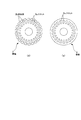
本発明の第2の実施例に係る誘導電動機のロータについて、図4を参照して説明する。
本実施例は、図4(a)(b)に示す通り、円形状鋼板を積層して形成される円筒状の積層鋼板1と、積層鋼板1の積層方向に貫通するスロット内に充填される2次導体(アルミバー)と、積層鋼板1の両端面に端板2を介して配置されるエンドリング3とを備え、更に、積層鋼板1のスロット内に2次導体としてアルミニウムをダイキャストにより形成すると共に積層鋼板1の両端面にエンドリング3としてアルミニウムをダイキャストにより形成する際に、積層鋼板1の外周面に円筒状薄膜4としてアルミニウムをダイキャストにより形成する点は前述した実施例と共通であり、同様な作用効果を奏するものである。
The rotor of the induction motor according to the second embodiment of the present invention will be described with reference to FIG.
In this embodiment, as shown in FIGS. 4A and 4B, a cylindrical laminated steel plate 1 formed by laminating circular steel plates and a slot penetrating in the lamination direction of the laminated steel plates 1 are filled. A secondary conductor (aluminum bar) and end rings 3 arranged on both end faces of the laminated steel plate 1 via the
更に、本実施例では、積層鋼板1の中心穴に一端側から耐腐食性材料(例えばSUS316)から成るボス6を挿入し、積層鋼板1の他端側においてボス6に耐腐食性材料(例えばSUS316)から成る固定具7を取付け(場合によっては溶接取付け)、その後、円筒状薄膜4及びエンドリング3に耐腐食性メッキ(例えば、無電解ニッケルメッキ)8を施すものである。
Further, in the present embodiment, a
ここで、上述した従来技術の欄で説明した通り、積層鋼板1の外周面は凹凸を有するため、密着性良く耐腐食性メッキを施すことが困難であった。
これに対し、本実施例では、図4(c)に示す通り、積層鋼板1の外周面に円筒状薄膜4がダイキャストにより形成され、積層鋼板1の外周面の凹凸は円筒状薄膜4により埋められ、円筒状薄膜4の表面は平滑であるので、円筒状薄膜4の表面に密着性の良い耐腐食性メッキ8を施すことができる。
Here, since the outer peripheral surface of the laminated steel sheet 1 has irregularities as described in the above-mentioned section of the prior art, it is difficult to perform corrosion-resistant plating with good adhesion.
On the other hand, in this embodiment, as shown in FIG. 4C, the cylindrical
しかも、円筒状薄膜4及びエンドリング3はアルミニウムであるので本来的に耐腐食性であるのに加え、更に、耐腐食性メッキ8を重ねているので、より、過酷な腐食環境下にも耐えることが可能となる。
なお、耐腐食性メッキ8を施す前に円筒状薄膜4をの表面を後加工(例えば、旋削等)することも可能である。
Moreover, since the cylindrical
Note that the surface of the cylindrical
本発明は、耐腐食性を持たせた誘導電動機のロータとして広く利用可能なものであり、特に、フッ素ガス中で使用される誘導電動機として好適なものである。 INDUSTRIAL APPLICABILITY The present invention can be widely used as a rotor for induction motors having corrosion resistance, and is particularly suitable as an induction motor used in fluorine gas.
1 積層鋼板
1a オープンスロット
1b クローズドスロット
2 端版
2a スロット(貫通孔)
2b 切欠部
3 エンドリング(アルミニウム)
4 円筒状薄膜(アルミニウム)
5 2次導体(アルミニウム)
6 ボス(耐腐食性材料)
7 固定具(耐腐食性材料)
8 耐腐食性メッキ
9,10 ダイキャスト型
10a 湯口
20 端部空隙
30 外周表面上隙間
DESCRIPTION OF SYMBOLS 1
4 Cylindrical thin film (aluminum)
5 Secondary conductor (aluminum)
6 Boss (corrosion resistant material)
7 Fixture (corrosion resistant material)
8 Corrosion-
Claims (10)
Priority Applications (1)
| Application Number | Priority Date | Filing Date | Title |
|---|---|---|---|
| JP2008168096A JP5407195B2 (en) | 2008-06-27 | 2008-06-27 | Induction motor rotor and method of manufacturing the same |
Applications Claiming Priority (1)
| Application Number | Priority Date | Filing Date | Title |
|---|---|---|---|
| JP2008168096A JP5407195B2 (en) | 2008-06-27 | 2008-06-27 | Induction motor rotor and method of manufacturing the same |
Publications (2)
| Publication Number | Publication Date |
|---|---|
| JP2010011641A true JP2010011641A (en) | 2010-01-14 |
| JP5407195B2 JP5407195B2 (en) | 2014-02-05 |
Family
ID=41591437
Family Applications (1)
| Application Number | Title | Priority Date | Filing Date |
|---|---|---|---|
| JP2008168096A Expired - Fee Related JP5407195B2 (en) | 2008-06-27 | 2008-06-27 | Induction motor rotor and method of manufacturing the same |
Country Status (1)
| Country | Link |
|---|---|
| JP (1) | JP5407195B2 (en) |
Cited By (3)
| Publication number | Priority date | Publication date | Assignee | Title |
|---|---|---|---|---|
| KR20140025272A (en) * | 2012-08-21 | 2014-03-04 | 가부시키가이샤 에바라 세이사꾸쇼 | Motor of vacuum pump and vacuum pump with the same |
| CN105006934A (en) * | 2015-07-02 | 2015-10-28 | 北京交通大学 | Motor structure with integration of sheath and rotor lamination core |
| JP2016158390A (en) * | 2015-02-24 | 2016-09-01 | 株式会社日立産機システム | Rotary electric machine and rotor thereof |
Citations (7)
| Publication number | Priority date | Publication date | Assignee | Title |
|---|---|---|---|---|
| JPS4854003U (en) * | 1971-10-27 | 1973-07-12 | ||
| JPH01170351A (en) * | 1987-12-21 | 1989-07-05 | Mitsubishi Electric Corp | Rotor for squirrel-cage type induction motor |
| JPH06261508A (en) * | 1991-03-20 | 1994-09-16 | Gold Star Co Ltd | Rotor of motor for canned pump |
| JPH09172759A (en) * | 1995-12-19 | 1997-06-30 | Matsushita Electric Ind Co Ltd | Motor driven compressor |
| JPH09215286A (en) * | 1996-02-02 | 1997-08-15 | Mitsubishi Electric Corp | Squirrel-cage induction motor and its manufacture |
| JPH11299144A (en) * | 1998-04-06 | 1999-10-29 | Shinko Electric Co Ltd | Structure of rotor and working of groove in high-speed rotary machine |
| JP2002519985A (en) * | 1998-06-29 | 2002-07-02 | シーメンス アクチエンゲゼルシヤフト | Electric motor |
-
2008
- 2008-06-27 JP JP2008168096A patent/JP5407195B2/en not_active Expired - Fee Related
Patent Citations (7)
| Publication number | Priority date | Publication date | Assignee | Title |
|---|---|---|---|---|
| JPS4854003U (en) * | 1971-10-27 | 1973-07-12 | ||
| JPH01170351A (en) * | 1987-12-21 | 1989-07-05 | Mitsubishi Electric Corp | Rotor for squirrel-cage type induction motor |
| JPH06261508A (en) * | 1991-03-20 | 1994-09-16 | Gold Star Co Ltd | Rotor of motor for canned pump |
| JPH09172759A (en) * | 1995-12-19 | 1997-06-30 | Matsushita Electric Ind Co Ltd | Motor driven compressor |
| JPH09215286A (en) * | 1996-02-02 | 1997-08-15 | Mitsubishi Electric Corp | Squirrel-cage induction motor and its manufacture |
| JPH11299144A (en) * | 1998-04-06 | 1999-10-29 | Shinko Electric Co Ltd | Structure of rotor and working of groove in high-speed rotary machine |
| JP2002519985A (en) * | 1998-06-29 | 2002-07-02 | シーメンス アクチエンゲゼルシヤフト | Electric motor |
Cited By (5)
| Publication number | Priority date | Publication date | Assignee | Title |
|---|---|---|---|---|
| KR20140025272A (en) * | 2012-08-21 | 2014-03-04 | 가부시키가이샤 에바라 세이사꾸쇼 | Motor of vacuum pump and vacuum pump with the same |
| JP2014042368A (en) * | 2012-08-21 | 2014-03-06 | Ebara Corp | Motor for vacuum pump and vacuum pump including the same |
| KR101966451B1 (en) | 2012-08-21 | 2019-04-05 | 가부시키가이샤 에바라 세이사꾸쇼 | Motor of vacuum pump and vacuum pump with the same |
| JP2016158390A (en) * | 2015-02-24 | 2016-09-01 | 株式会社日立産機システム | Rotary electric machine and rotor thereof |
| CN105006934A (en) * | 2015-07-02 | 2015-10-28 | 北京交通大学 | Motor structure with integration of sheath and rotor lamination core |
Also Published As
| Publication number | Publication date |
|---|---|
| JP5407195B2 (en) | 2014-02-05 |
Similar Documents
| Publication | Publication Date | Title |
|---|---|---|
| US9083221B2 (en) | Rotor assembly with integral cast conductor bars and first end rings and welded second end rings and method of manufacturing same | |
| JP5859297B2 (en) | Rotating electric machine | |
| TWI717940B (en) | Adhesive laminated iron core for stator and rotating electric machine | |
| TWI733277B (en) | Adhesive laminated iron core for stator and rotating electric machine | |
| US10797541B2 (en) | Magnetic plate laminate, manufacturing method therefor, and motor using this laminate | |
| JP7412351B2 (en) | Laminated core and rotating electrical machinery | |
| US11031838B2 (en) | Housing unit for an electric machine | |
| CA3131495A1 (en) | Adhesively-laminated core for stator and electric motor | |
| JP2012120299A (en) | Stator core, rotary electric machine, and manufacturing method of stator core | |
| JP2010142038A (en) | Method of manufacturing rotor of rotary electric machine, and rotor | |
| JP5407195B2 (en) | Induction motor rotor and method of manufacturing the same | |
| TWI420785B (en) | Rotary electric machine and method for making a rotary electric machine | |
| JP2007151360A (en) | Method of manufacturing laminate | |
| JP5121632B2 (en) | Rotating electric machine, stator core thereof, and method of manufacturing stator core | |
| JP6069475B2 (en) | Rotating electric machine | |
| JP5287304B2 (en) | Rotating electric machine | |
| TW201409901A (en) | Split stator core parts in electric motor of can conformation and stator core as well as electric motor using the same | |
| TWI792355B (en) | Electromagnetic steel sheets, laminated iron cores, and rotating electrical machines | |
| JP4811047B2 (en) | Concentrated winding motor | |
| JP2010193623A (en) | Squirrel cage rotor for electric motor, electric motor, submersible pump, and method of manufacturing them | |
| JP7092646B2 (en) | Motor core | |
| JP2004040984A (en) | Rotor of motor | |
| JP2020156153A (en) | Rotator of rotary electric machine and rotator manufacturing method | |
| JP7310141B2 (en) | Rotor of rotary electric machine | |
| WO2011101985A1 (en) | Stator and method for producing same |
Legal Events
| Date | Code | Title | Description |
|---|---|---|---|
| A621 | Written request for application examination |
Free format text: JAPANESE INTERMEDIATE CODE: A621 Effective date: 20110517 |
|
| A711 | Notification of change in applicant |
Free format text: JAPANESE INTERMEDIATE CODE: A711 Effective date: 20110517 |
|
| A521 | Written amendment |
Free format text: JAPANESE INTERMEDIATE CODE: A821 Effective date: 20110517 |
|
| A131 | Notification of reasons for refusal |
Free format text: JAPANESE INTERMEDIATE CODE: A131 Effective date: 20130326 |
|
| A521 | Written amendment |
Free format text: JAPANESE INTERMEDIATE CODE: A523 Effective date: 20130510 |
|
| A01 | Written decision to grant a patent or to grant a registration (utility model) |
Free format text: JAPANESE INTERMEDIATE CODE: A01 Effective date: 20131008 |
|
| A61 | First payment of annual fees (during grant procedure) |
Free format text: JAPANESE INTERMEDIATE CODE: A61 Effective date: 20131021 |
|
| LAPS | Cancellation because of no payment of annual fees |