US10797541B2 - Magnetic plate laminate, manufacturing method therefor, and motor using this laminate - Google Patents
Magnetic plate laminate, manufacturing method therefor, and motor using this laminate Download PDFInfo
- Publication number
- US10797541B2 US10797541B2 US16/240,015 US201916240015A US10797541B2 US 10797541 B2 US10797541 B2 US 10797541B2 US 201916240015 A US201916240015 A US 201916240015A US 10797541 B2 US10797541 B2 US 10797541B2
- Authority
- US
- United States
- Prior art keywords
- magnetic
- laminate
- fastening member
- plate
- plate laminate
- Prior art date
- Legal status (The legal status is an assumption and is not a legal conclusion. Google has not performed a legal analysis and makes no representation as to the accuracy of the status listed.)
- Expired - Fee Related
Links
- 238000004519 manufacturing process Methods 0.000 title claims abstract description 16
- 238000000034 method Methods 0.000 claims abstract description 15
- 239000000463 material Substances 0.000 claims description 20
- XEEYBQQBJWHFJM-UHFFFAOYSA-N Iron Chemical compound [Fe] XEEYBQQBJWHFJM-UHFFFAOYSA-N 0.000 claims description 14
- 238000009413 insulation Methods 0.000 claims description 9
- 229910052751 metal Inorganic materials 0.000 claims description 8
- 239000002184 metal Substances 0.000 claims description 8
- 230000002093 peripheral effect Effects 0.000 claims description 8
- 229910045601 alloy Inorganic materials 0.000 claims description 7
- 239000000956 alloy Substances 0.000 claims description 7
- 229910052742 iron Inorganic materials 0.000 claims description 5
- 239000007787 solid Substances 0.000 claims description 5
- 239000002159 nanocrystal Substances 0.000 claims description 4
- 238000010438 heat treatment Methods 0.000 abstract description 4
- 238000003475 lamination Methods 0.000 description 12
- 230000007246 mechanism Effects 0.000 description 7
- 239000011347 resin Substances 0.000 description 7
- 229920005989 resin Polymers 0.000 description 7
- 239000000853 adhesive Substances 0.000 description 6
- 230000001070 adhesive effect Effects 0.000 description 6
- 238000010586 diagram Methods 0.000 description 6
- 238000010030 laminating Methods 0.000 description 5
- 229910000808 amorphous metal alloy Inorganic materials 0.000 description 4
- 238000003825 pressing Methods 0.000 description 4
- 238000004804 winding Methods 0.000 description 4
- 229910001369 Brass Inorganic materials 0.000 description 3
- CWYNVVGOOAEACU-UHFFFAOYSA-N Fe2+ Chemical compound [Fe+2] CWYNVVGOOAEACU-UHFFFAOYSA-N 0.000 description 3
- 229910000831 Steel Inorganic materials 0.000 description 3
- 230000008901 benefit Effects 0.000 description 3
- 230000015572 biosynthetic process Effects 0.000 description 3
- 239000010951 brass Substances 0.000 description 3
- 230000000694 effects Effects 0.000 description 3
- 239000000696 magnetic material Substances 0.000 description 3
- 238000002844 melting Methods 0.000 description 3
- 230000008018 melting Effects 0.000 description 3
- 239000010959 steel Substances 0.000 description 3
- 229910000838 Al alloy Inorganic materials 0.000 description 2
- RYGMFSIKBFXOCR-UHFFFAOYSA-N Copper Chemical compound [Cu] RYGMFSIKBFXOCR-UHFFFAOYSA-N 0.000 description 2
- 229910052782 aluminium Inorganic materials 0.000 description 2
- XAGFODPZIPBFFR-UHFFFAOYSA-N aluminium Chemical compound [Al] XAGFODPZIPBFFR-UHFFFAOYSA-N 0.000 description 2
- 229910000963 austenitic stainless steel Inorganic materials 0.000 description 2
- 230000033228 biological regulation Effects 0.000 description 2
- 230000006835 compression Effects 0.000 description 2
- 238000007906 compression Methods 0.000 description 2
- 229910052802 copper Inorganic materials 0.000 description 2
- 239000010949 copper Substances 0.000 description 2
- 238000002425 crystallisation Methods 0.000 description 2
- 230000008025 crystallization Effects 0.000 description 2
- 238000005520 cutting process Methods 0.000 description 2
- 230000007423 decrease Effects 0.000 description 2
- 229910000679 solder Inorganic materials 0.000 description 2
- 230000002596 correlated effect Effects 0.000 description 1
- 230000008878 coupling Effects 0.000 description 1
- 238000010168 coupling process Methods 0.000 description 1
- 238000005859 coupling reaction Methods 0.000 description 1
- 238000009826 distribution Methods 0.000 description 1
- 238000005530 etching Methods 0.000 description 1
- 238000003780 insertion Methods 0.000 description 1
- 230000037431 insertion Effects 0.000 description 1
- 239000007788 liquid Substances 0.000 description 1
- 238000003754 machining Methods 0.000 description 1
- 239000000203 mixture Substances 0.000 description 1
- 238000004080 punching Methods 0.000 description 1
- 238000010791 quenching Methods 0.000 description 1
- 230000000171 quenching effect Effects 0.000 description 1
Images


Classifications
-
- H—ELECTRICITY
- H02—GENERATION; CONVERSION OR DISTRIBUTION OF ELECTRIC POWER
- H02K—DYNAMO-ELECTRIC MACHINES
- H02K1/00—Details of the magnetic circuit
- H02K1/06—Details of the magnetic circuit characterised by the shape, form or construction
- H02K1/12—Stationary parts of the magnetic circuit
- H02K1/18—Means for mounting or fastening magnetic stationary parts on to, or to, the stator structures
- H02K1/185—Means for mounting or fastening magnetic stationary parts on to, or to, the stator structures to outer stators
-
- H—ELECTRICITY
- H02—GENERATION; CONVERSION OR DISTRIBUTION OF ELECTRIC POWER
- H02K—DYNAMO-ELECTRIC MACHINES
- H02K1/00—Details of the magnetic circuit
- H02K1/06—Details of the magnetic circuit characterised by the shape, form or construction
- H02K1/12—Stationary parts of the magnetic circuit
- H02K1/14—Stator cores with salient poles
- H02K1/146—Stator cores with salient poles consisting of a generally annular yoke with salient poles
-
- H—ELECTRICITY
- H02—GENERATION; CONVERSION OR DISTRIBUTION OF ELECTRIC POWER
- H02K—DYNAMO-ELECTRIC MACHINES
- H02K15/00—Processes or apparatus specially adapted for manufacturing, assembling, maintaining or repairing of dynamo-electric machines
- H02K15/02—Processes or apparatus specially adapted for manufacturing, assembling, maintaining or repairing of dynamo-electric machines of stator or rotor bodies
- H02K15/021—Magnetic cores
- H02K15/022—Magnetic cores with salient poles
-
- H—ELECTRICITY
- H02—GENERATION; CONVERSION OR DISTRIBUTION OF ELECTRIC POWER
- H02K—DYNAMO-ELECTRIC MACHINES
- H02K2201/00—Specific aspects not provided for in the other groups of this subclass relating to the magnetic circuits
- H02K2201/09—Magnetic cores comprising laminations characterised by being fastened by caulking
Definitions
- the present invention relates to a magnetic-plate laminate formed by laminating soft magnetic thin strips, and also to a motor which uses this laminate as a stator.
- the stator iron core according to PTL 1 is formed by machining first the amorphous alloy thin strips made by a liquid quenching method such as a single roll technique or a twin roll technique in a predetermined shape by a method such as winding, cutting, punching and etching.
- FIG. 16 illustrates a perspective view of an amorphous lamination member 51 according to PTL 2.
- the lamination member 51 is manufactured by overlapping, from upper and lower sides, electromagnetic steel plates 53 on a plurality of sheets of the amorphous alloy thin strips 52 to which an adhesive has been applied, and heating and pressure-bonding the amorphous alloy thin strips 52 . Consequently, handling is easy.
- the adhesive enters between the layers of the amorphous thin strips, and therefore there are problems that a space factor is poor and motor efficiency becomes poor.
- the present invention solves the conventional problems, and an object of the present invention is to provide a magnetic-plate laminate which has high productivity without impairing magnetic characteristics, and a motor which uses this laminate.
- a magnetic-plate laminate including: a laminate in which a plurality of thin strips are laminated; and a fastening member that is provided in an opening of the laminate. Furthermore, there is used a method for manufacturing the magnetic-plate laminate, in which the magnetic-plate laminate in which the thin strips are amorphous thin strips is thermally processed to cause the stripes to have a nanocrystal grain.
- a motor including: a stator in which a plurality of the magnetic-plate laminates are laminated; a fixing plate that fixes the stator; and a rotor that is disposed in an opening at a center of the stator.
- a magnetic-plate laminate according to the present invention can simultaneously handle a plurality of positioned thin strips and, consequently, not only has high productivity but also does not include a material which decreases a ratio of a magnetic member in a unit volume such as an adhesive between layers, therefore has a high space factor and can prevent a decrease in magnetic characteristics.
- the magnetic-plate laminate according to the present invention has high productivity without impairing magnetic characteristics.
- FIG. 1A is a side view of a fastening member which fastens a laminate according to Embodiment 1;
- FIG. 1B is a broken cross-sectional view illustrating a manufacturing process of a magnetic-plate laminate for which an eyelet structure is used according to Embodiment 1;
- FIG. 1C is a broken cross-sectional view illustrating the manufacturing process of the magnetic-plate laminate for which the eyelet structure is used according to Embodiment 1;
- FIG. 1D is a broken cross-sectional view illustrating the manufacturing process of the magnetic-plate laminate for which the eyelet structure is used according to Embodiment 1;
- FIG. 2 is a broken cross-sectional view illustrating a state where the laminated laminate is fixed by eyelet members according to Embodiment 2;
- FIG. 3 is an external outlook view of the eyelet member of the magnetic-plate laminate according to Embodiment 2;
- FIG. 4A is a broken cross-sectional view illustrating the manufacturing process of the magnetic-plate laminate according to Embodiment 3;
- FIG. 4B is a broken cross-sectional view illustrating the manufacturing process of the magnetic-plate laminate according to Embodiment 3;
- FIG. 4C is a broken cross-sectional view illustrating the manufacturing process of the 1 magnetic-plate laminate according to Embodiment 3;
- FIG. 5 is a broken cross-sectional view illustrating a state where the laminated laminate is fixed by the caulking members according to Embodiment 3;
- FIG. 6A is a broken cross-sectional view illustrating a process of forming the eyelet structures of the magnetic-plate laminate according to Embodiment 4;
- FIG. 6B is a broken cross-sectional view illustrating a process of forming the eyelet structures of the magnetic-plate laminate according to Embodiment 4;
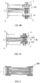
- FIG. 7A is a broken cross-sectional view illustrating the manufacturing process of the magnetic-plate laminate for which a caulking structure is used according to Embodiment 5;
- FIG. 7B is a broken cross-sectional view illustrating the magnetic-plate laminate for which the caulking structure is used according to Embodiment 5;
- FIG. 7C is a broken cross-sectional view illustrating the manufacturing process of the magnetic-plate laminate for which the caulking structure is used according to Embodiment 5;
- FIG. 8 is an enlarged broken cross-sectional view near the caulking member of the magnetic-plate laminate according to Embodiment 6;
- FIG. 9 is an enlarged broken cross-sectional view near the caulking member of the magnetic-plate laminate according to Embodiment 7;
- FIG. 10A is a side view of a motor formed by the magnetic-plate laminate according to Embodiment 8.
- FIG. 10B is a top view of the motor formed by the magnetic-plate laminate according to Embodiment 8.
- FIG. 11A is a broken cross-sectional view between A and A′ in FIG. 10B according to Embodiment 8;
- FIG. 11B is a broken cross-sectional view between A and A′ in FIG. 10B according to Embodiment 8;
- FIG. 12 is an enlarged broken cross-sectional view near the eyelet portions of the magnetic-plate laminate according to Embodiment 9;
- FIG. 13A is a side view of the motor formed by the magnetic-plate laminate according to Embodiment 10.
- FIG. 13B is a top view of the motor formed by the magnetic-plate laminate according to Embodiment 10;
- FIG. 14 is a broken cross-sectional view between B and B′ in FIG. 13B according to Embodiment 10;
- FIG. 15 is a broken cross-sectional view between B and B′ in FIG. 13B ;
- FIG. 16 is a perspective view illustrating a conventional magnetic-plate laminate disclosed in PTL 2.
- FIG. 1A is a side view of fastening member 100 a which fastens magnetic-plate laminate 1 .
- FIGS. 1B to 1D are schematic views illustrating a manufacturing process of magnetic-plate laminate 1 according to Embodiment 1, and, more specifically, illustrate that an eyelet structure is used as a metal fastening mechanism.
- Fastening member 100 a includes a plurality of planar portions 2 a which are partitioned by cuts at both ends of hollow cylinder 2 .
- eyelet structure 3 a is a structure that planar portions 2 a are located at the both ends of hollow cylinder 2 in a vertical direction of the cylinder. Eyelet structure 3 a is fitted in opening 4 formed in magnetic-plate laminate 1 formed by laminating thin strips which are magnetic bodies. Eyelet structure 3 a includes planar portions 2 a at the both ends of hollow cylinder 2 so as not to be detached easily from opening 4 . As a result, eyelet structure 3 a can collectively fix magnetic-plate laminate 1 formed by laminating a plurality of thin strips. Furthermore, eyelet structure 3 a is also referred to as a grommet or an eyelet.
- hollow cylinder 2 may be a columnar type or a polygonal columnar shape.
- FIGS. 1B to 1D illustrate laminate 1 , hollow cylinder 2 , planar portions 2 a formed at cuts on hollow cylinder 2 , and opening 4 formed in magnetic-plate laminate 1 .
- Opening 4 is a hole which penetrates magnetic-plate laminate 1 .
- the fastening member in FIG. 1A is inserted in this opening 4 .
- the fastening member in FIG. 1B including hollow cylinder 2 and planar portions 2 a is inserted in opening 4 of magnetic-plate laminate 1 in an arrow direction.
- laminated magnetic-plate laminate 1 is fixed by pressing mechanisms 5 , and eyelet fittings 6 are butted from upper and lower sides in arrow directions to push open planar portions 2 a.
- compressing fittings 7 perform compression from the arrow directions (from the upper and lower sides) to make planar portions 2 a face left and right directions to form eyelet structure 3 a .
- the compression may be height regulation which can keep the fixed height of the eyelet, or pressure regulation which can make the eyelet firm.
- FIG. 2 is a cross-sectional view illustrating a state where laminated magnetic-plate laminate 1 is fixed by eyelet structures 3 a.
- Magnetic-plate laminate 1 is formed by laminating the thin strips.
- the thin strip is an amorphous magnetic plate.
- the plate thickness of the thin strip obtained in an amorphous state is usually between 10 and 100 ⁇ m.
- the thin strip may be an amorphous thin strip crystalized by heat processing.
- a material of fastening member 100 a is desirably a non-magnetic material which is not influenced by a magnetic field from a viewpoint that this material does not influence magnetic characteristics of magnetic-plate laminate 1 .
- this non-magnetic material an iron-based material such as austenitic stainless steel, or a non-ferrous metal such as a cooper, a copper-based alloy such as brass, aluminum or an aluminum alloy, or an alloy of these metal can be used.
- Eyelet structure 3 a of fastening member 100 a made of brass fixes 30 sheets of amorphous thin strips (thin strips) to handle as one magnetic-plate laminate 1 .
- the thicknesses of upper and lower planar portions 2 a of eyelet structure 3 a are 60 ⁇ m in total, and, when the thickness of the thin strip (thin strip) is 30 ⁇ m, a space factor indicating occupation of the thin strips in a lamination thickness direction is approximately 94%. As the plate thicknesses and the number of sheets of the thin strips are larger and planar portions 2 a are thinner, the space factor is higher.
- a lamination thickness limit of the thin strips depends on eyelet structure 3 a , and, as the lamination thickness is thicker, planar portions 2 a and thicker eyelet structure 3 a are necessary.
- Eyelet structure 3 a may be formed in magnetic-plate laminate 1 of the crystalized thin strips or eyelet structure 3 a may be formed in magnetic-plate laminate 1 of the amorphous thin strips, then be thermally processed and crystallized.
- a crystallization temperature varies based on a composition and is usually between 350° C. and 500° C., and when a nanocrystal grain whose diameter is several 10 nm or less is included in the thin strip, the thin strip has better soft magnetic characteristics than an amorphous member.
- the thin strip becomes fragile, and therefore when eyelet structure 3 a is formed after the crystallization, it is necessary to pay attention not to break the thin strips.
- the thickness of magnetic-plate laminate 1 is preferably the thickness equal to or less than 2.5 mm to suppress the excessive temperature rise. This shows that desired magnetic characteristics can be obtained. In this case, some of laminates 1 can be laminated to form one thick magnetic-plate laminate 1 .
- the entire thickness of magnetic-plate laminate 1 is 2.5 mm, and the plate thickness of one sheet of a thin strip is minimum 10 ⁇ m, 250 sheets of thin strips need to be laminated at maximum. Furthermore, a plurality of sheets of thin strips is laminated and manufactured to enhance productivity. The entire thickness in a case of two sheets of the laminated thin strips is 0.02 mm since the plate thickness of the thin strip is 10 ⁇ m.
- This eyelet structure 3 a makes it easy to transfer heat in the lamination direction of magnetic-plate laminate 1 and contributes to making the temperature gradient in the lamination direction small.
- a layer of the oxide has an insulation property, and consequently contributes to preventing electrical short-circuiting between laminated magnetic-plate laminate 1 and eyelet structure 3 a , and can reduce energy loss due to eddy current loss caused by short-circuiting in a magnetic device such as a motor.
- FIG. 3 is an external outlook view of fastening member 100 b according to Embodiment 2.
- a difference of FIG. 3 from fastening member 100 a in FIG. 1A is that planar portion 2 b is vertically bent on one side from hollow cylinder 2 from the beginning Planar portions 2 a are disposed in parallel to hollow cylinder 2 on the other side.
- a formation process of eyelet structure 3 a and a shape after formation of eyelet structure 3 a are equivalent to those in FIGS. 1D and 2 . Matters which are not described are the same as those in Embodiment 1.
- FIGS. 4A to 4C are schematic views illustrating a manufacturing process of magnetic-plate laminate 1 of a magnetic plate according to Embodiment 3. More specifically, FIGS. 4A to 4C illustrate that fastening member 100 c is used for a metal fastening mechanism, and caulking structure 3 b is formed.
- planar portions 10 a are located at both ends of solid columnar body 10 in this structure.
- One end widens as planar portions 10 a to intend to collectively fix the laminated thin strips.
- planar portion 10 a is formed unlike planar portions 2 a and 2 b .
- planar portion 10 a may be divided into several portions. Matters which are not described are the same as those in Embodiment 1.
- FIGS. 4A to 4C A difference of FIGS. 4A to 4C from FIGS. 1B to 1D is that fastening member 100 c is used.
- fastening member 100 c is inserted in opening 4 of laminated magnetic-plate laminate 1 in an arrow direction.
- fastening member 100 c is fixed by pressing mechanisms 5 , and compressing fittings 7 are butted from upper and lower sides in arrow directions.
- compressing fittings 7 can compress columnar body 10 in the arrow directions to form planar portions 10 a on the upper and lower sides of columnar body 10 in a vertical direction and form caulking structure 3 b.
- FIG. 5 is a cross-sectional view illustrating a state where laminated magnetic-plate laminate 1 is fixed by caulking structure 3 b .
- a material of fastening member 100 c which forms caulking structure 3 b is desirably a non-magnetic material which is not influenced by a magnetic field from a viewpoint that this material does not influence magnetic characteristics of magnetic-plate laminate 1 similar to eyelet structure 3 a .
- an iron-based material such as austenitic stainless steel, or a non-ferrous metal such as a cooper, a copper-based alloy such as brass, aluminum or an aluminum alloy, or an alloy of these can be used.
- FIGS. 6A and 6B are schematic views illustrating a process of forming eyelet structures 3 c of magnetic-plate laminate 1 of a magnetic plate according to Embodiment 4.
- opening 55 is made by drill 12 at an axial center of one of two caulking structures 3 b formed in laminated magnetic-plate laminate 1 .
- FIG. 6B when openings 55 are made at two portions, eyelet structures 3 c are formed.
- a cutting mark is left in the inner wall of the opening of eyelet structure 3 c .
- Irregularity 24 is preferably 10 nm or more.
- FIGS. 7A to 7C are schematic views illustrating a manufacturing process of magnetic-plate laminate 1 according to Embodiment 5, and illustrate magnetic-plate laminate 1 for which caulking structure 3 d is used.
- a difference of FIGS. 7A to 7C from FIGS. 4A to 4C is that a columnar fastening member 100 d is used.
- fastening member 100 d which is longer than the depth of opening 4 and is larger than the volume of opening 4 is inserted in opening 4 of laminated magnetic-plate laminate 1 in an arrow direction.
- laminated magnetic-plate laminate 1 is fixed by pressing mechanisms 5 , and caulking fittings 16 having counterbored portions 15 are butted from upper and lower sides in arrow directions.
- caulking fittings 16 compress fastening member 100 d in the arrow directions, so that part of fastening member 100 d plastically flow and is loaded to counterbored portions 15 to form guards on the upper and lower sides and fix laminated magnetic-plate laminate 1 by caulking structure 3 d .
- the shape of fastening member 100 d may be a prismatic shape or a spherical shape other than the columnar shape. Matters which are not described are the same as those in the above embodiments.
- FIG. 8 is an enlarged cross-sectional view near caulking structure 3 d of magnetic-plate laminate 1 according to Embodiment 6.
- a non-ferrous material has lower hardness than an iron-based material as a material of caulking structure 3 d , and can be caulked with a small load.
- projection portions 21 are located on a side surface of the columnar portion of caulking structure 3 d .
- a plurality of projection portions 21 is preferably provided.
- An eyelet structure also needs to include these projection portions 21 .
- FIG. 9 is an enlarged cross-sectional view near fastening member 100 d of a magnetic-plate laminate according to Embodiment 7.
- a difference of fastening member 100 d in FIG. 9 from caulking structure 3 b in FIG. 5 is that an outer peripheral portion of fastening member 100 d is provided with insulation layer 23 .
- insulation layer 23 such as a resin which can deform on an outer peripheral portion of caulking member 14 , and performing caulking in the same process as those in FIGS. 7B and 7C , a structure in FIG. 9 can be obtained.
- insulation layer 23 on outer peripheral of fastening member 100 d , it is possible to prevent electrical short-circuiting between laminated magnetic-plate laminate 1 and fastening member 100 d , and reduce energy loss due to eddy current loss caused by short-circuiting in a magnetic device such as a motor. Matters which are not described are the same as those in the above embodiments.
- above fastening members 100 a to 100 c also include insulation layers 23 on outer peripheral surfaces or inner peripheral surfaces of fastening members 100 a to 100 c likewise.
- FIGS. 10A and 10B are external outlook configuration diagrams of a motor formed by magnetic-plate laminate 1 of a magnetic plate according to Embodiment 8.
- FIG. 10A is a side view of the motor
- FIG. 10B is a top view of the motor.
- stator 31 which is a laminated object of thin strips is fixed to fixing plate 32 by bolts 33 , spring washers 34 , washers 35 and nuts 36 .
- windings 38 are provided to portions which are called teeth (T-shaped protrusion portions) of stator 31 .
- Rotor 37 is installed on an inner diameter side (opening portion) of stator 31 .
- FIGS. 11A and 11B are cross-sectional configuration diagrams between A and A′ in FIG. 10B , FIG. 11A illustrates a state without fixing bolts 33 and FIG. 11B illustrates a state with bolts 33 .
- laminates 41 of eyelet structures 3 a and 3 c which form stator 31 are positioned such that portions of eyelet structures 3 a and 3 c are stacked on through-hole 42 for fastening fixing plate 32 , and are laminated at three stages.
- Metal fastening mechanisms (openings 4 and fastening members 100 a and 100 b ) are linearly arranged in a thickness direction of stator 31 .
- laminates 41 of eyelet structures 3 a and 3 c are fixed to fixing plate 32 by bolts 33 , spring washers 34 , washers 35 and nuts 36 .
- bolts 33 By inserting bolts 33 in eyelet structures 3 a and 3 c in openings 4 of laminates 41 , it is possible to prevent damages on end surfaces of the thin strips during insertion of the bolts 33 .
- fastening pressures of the bolts 33 locally work on the thin strips, so that it is possible to prevent a negative influence on magnetic characteristics of laminates 41 .
- Laminates 41 are used for stator 31 . However, laminates 41 may be used for rotor 37 . A motor whose rotor 37 rotates around stator 31 may be used.
- FIG. 12 is an enlarged cross-sectional configuration diagram near eyelet structure 3 c of stator 31 of a motor according to Embodiment 9.
- Laminates 41 of eyelet structures 3 c including fastening members 100 e with insulation layers 23 are laminated at three stages.
- adhesive 43 is applied to an inner wall of opening 4 inside fastening member 100 e to couple laminates 41 of three stages.
- Adhesive 43 is used for coupling in FIG. 12 .
- fastening members 100 e may be welded to each other or fastening members 100 e may be caulked to each other. Matters which are not described are the same as those in Embodiment 8.
- FIGS. 13A and 13B are external outlook configuration diagrams of a motor formed by a magnetic-plate laminate according to Embodiment 10, FIG. 13A is a side view and FIG. 13B is a top view.
- the motor in FIGS. 13A and 13B is different from a motor in FIGS. 10A and 10B according to Embodiment 8.
- Difference points include that (1) stator 31 which is a laminated object of thin strips is fixed at three portions of fixing plate 32 by bolts 33 , spring washers 34 , washers 35 and nuts 36 , and (2) resin portions 44 loaded in openings 4 of the fastening members are provided at three portions. That T-shaped portions which are called teeth of stator 31 are wound by windings 38 and rotor 37 is installed on an inner diameter side of stator 31 is the same as that in FIGS. 10A and 10B .
- FIG. 14 is a cross-sectional configuration diagram between B and B′ in above FIG. 13 B, and illustrates a state where laminates 45 of eyelet structures 100 a , 100 b and 100 e are laminated before fixing bolts 33 and resin portions 44 are inserted.
- Laminates 45 of the eyelet structures which form stator 31 are laminated at five stages such that through-holes 46 and hollow portions 47 of fastening members 100 e are alternately stacked. That is, fastening members 100 e adjacent on the upper and lower sides are located at different positions in a plan view of stator 31 . Alternatively, fastening members 100 e adjacent on the upper and lower sides are not combined.
- This configuration provides an effect that upper and lower gaps 48 of laminated magnetic-plate laminate 1 narrow and a space factor is high compared to a case where eyelet structures 3 a and 3 c are stacked and laminated at three states in FIG. 11A in Embodiment 8.
- FIG. 15 is a cross-sectional configuration diagram between B and B′ in above FIG. 13B , and illustrates a state where laminates 45 of the eyelet structures are laminated and fixed after fixing bolts 33 and resin portions 44 are inserted.
- Laminates 45 of the eyelet structures are fixed to fixing plate 32 by bolts 33 , spring washers 34 , washers 35 and nuts 36 via through-holes 46 and hollow portions 47 of fastening members 100 e .
- resin portions 44 loaded to keep rigidity are formed in laminates 45 in which bolts 33 are not inserted. Even when resin portions 44 are hollow, other materials may be loaded. Matters which are not described are the same as those in Embodiments 8 and 9.
- the embodiments can be combined.
- the eyelet members and the caulking members may be columns, columnar cylinders, square columns or elliptical columns.
- present disclosure includes any combination of optional embodiments and/or examples among the above-described various embodiments and/or examples, and can provide the effects of the respective embodiments and/or examples.
- the magnetic-plate laminate according to the present invention can provide the magnetic-plate laminate which has high productivity without impairing magnetic characteristics. Consequently, the magnetic-plate laminate according to the present invention is useful as the stator of the motor. Furthermore, the magnetic-plate laminate according to the present invention is applicable for use in magnetic application electronic parts such as transformers other than motors.
Landscapes
- Engineering & Computer Science (AREA)
- Power Engineering (AREA)
- Manufacturing & Machinery (AREA)
- Iron Core Of Rotating Electric Machines (AREA)
- Manufacture Of Motors, Generators (AREA)
- Manufacturing Cores, Coils, And Magnets (AREA)
Abstract
Description
- 1 Magnetic-plate laminate
- 2 Hollow cylinder
- 2 a, 2 b Planar portion
- 3 a, 3 c Eyelet structure
- 3 b, 3 d, 3 e Caulking structure
- 4 Opening
- 5 Pressing mechanism
- 6 Eyelet fitting
- 7 Compressing fitting
- 10 Columnar body
- 10 a Planar portion
- 12 Drill
- 15 Counterbored portion
- 16 Caulking fitting
- 19 Thin strip
- 20 Gap
- 21 Projection portion
- 23 Insulation layer
- 24 Irregularity
- 31 Stator
- 32 Fixing plate
- 33 Bolt
- 34 Spring washer
- 35 Washer
- 36 Nut
- 37 Rotor
- 38 Winding
- 41 Laminate
- 42 Through-hole
- 43 Adhesive
- 44 Resin portion
- 45 Laminate
- 46 Through-hole
- 47 Hollow portion
- 48 Gap
- 51 Lamination member
- 52 Amorphous alloy thin strip
- 53 Electromagnetic steel plate
- 55 Opening
- 100 a, 100 b, 100 c, 100 d, 100 e Fastening member
Claims (11)
Applications Claiming Priority (3)
| Application Number | Priority Date | Filing Date | Title |
|---|---|---|---|
| JP2016-133842 | 2016-07-06 | ||
| JP2016133842 | 2016-07-06 | ||
| PCT/JP2017/023005 WO2018008417A1 (en) | 2016-07-06 | 2017-06-22 | Magnetic plate laminate, manufacturing method therefor, and motor using this laminate |
Related Parent Applications (1)
| Application Number | Title | Priority Date | Filing Date |
|---|---|---|---|
| PCT/JP2017/023005 Continuation WO2018008417A1 (en) | 2016-07-06 | 2017-06-22 | Magnetic plate laminate, manufacturing method therefor, and motor using this laminate |
Publications (2)
| Publication Number | Publication Date |
|---|---|
| US20190157921A1 US20190157921A1 (en) | 2019-05-23 |
| US10797541B2 true US10797541B2 (en) | 2020-10-06 |
Family
ID=60912629
Family Applications (1)
| Application Number | Title | Priority Date | Filing Date |
|---|---|---|---|
| US16/240,015 Expired - Fee Related US10797541B2 (en) | 2016-07-06 | 2019-01-04 | Magnetic plate laminate, manufacturing method therefor, and motor using this laminate |
Country Status (5)
| Country | Link |
|---|---|
| US (1) | US10797541B2 (en) |
| EP (1) | EP3484017A4 (en) |
| JP (2) | JP6880020B2 (en) |
| CN (1) | CN109417318A (en) |
| WO (1) | WO2018008417A1 (en) |
Families Citing this family (14)
| Publication number | Priority date | Publication date | Assignee | Title |
|---|---|---|---|---|
| WO2018150807A1 (en) * | 2017-02-14 | 2018-08-23 | パナソニック株式会社 | Thin strip component, method for manufacturing same, and motor using thin strip component |
| DE102018205806A1 (en) * | 2018-04-17 | 2019-10-17 | Siemens Aktiengesellschaft | Stator, electric machine, aircraft with an electric machine and method of manufacturing a stator |
| WO2020044745A1 (en) * | 2018-08-28 | 2020-03-05 | パナソニックIpマネジメント株式会社 | Method of manufacturing stator, stator, and motor |
| JP7095654B2 (en) | 2019-05-23 | 2022-07-05 | トヨタ自動車株式会社 | Metal leaf manufacturing method |
| JP6885443B2 (en) * | 2019-10-28 | 2021-06-16 | 三菱電機ビルテクノサービス株式会社 | Elevator guide rail refueling body, refueling device and processing jig |
| JP7347197B2 (en) * | 2019-12-19 | 2023-09-20 | トヨタ自動車株式会社 | Manufacturing method and manufacturing device for rotating electrical machine core |
| CN111064335B (en) * | 2020-01-02 | 2021-07-09 | 东南大学 | An E-type double-winding stator axial flux motor with amorphous material |
| JP7318536B2 (en) * | 2020-01-08 | 2023-08-01 | トヨタ自動車株式会社 | METHOD AND APPARATUS FOR MANUFACTURING METAL FOIL |
| DE112021000423T5 (en) * | 2020-04-01 | 2022-10-13 | Fanuc Corporation | Stator, rotor and rotating electric machine |
| DE102020207815A1 (en) * | 2020-06-24 | 2021-12-30 | Zf Friedrichshafen Ag | Screw connection, electrical machine and motor vehicle drive unit |
| JP7392604B2 (en) * | 2020-07-29 | 2023-12-06 | トヨタ紡織株式会社 | Stator core, stator core manufacturing method, and stator core manufacturing device |
| JP7485949B2 (en) | 2020-09-29 | 2024-05-17 | ダイキン工業株式会社 | motor |
| JP7637495B2 (en) * | 2020-11-20 | 2025-02-28 | ミネベアミツミ株式会社 | Motor |
| DE102023210193A1 (en) * | 2023-10-18 | 2025-04-24 | Zf Friedrichshafen Ag | Electrical machine with a non-positively and positively secured laminated core and method for assembling the electrical machine |
Citations (29)
| Publication number | Priority date | Publication date | Assignee | Title |
|---|---|---|---|---|
| DE1808577A1 (en) | 1967-11-16 | 1969-08-14 | Cem Comp Electro Mec | Stator for a surge alternating current generator |
| JPS4985502A (en) | 1972-12-23 | 1974-08-16 | ||
| JPS61123672U (en) | 1985-01-18 | 1986-08-04 | ||
| JPS61258655A (en) | 1985-05-07 | 1986-11-17 | Toshiba Corp | Securing method for laminated core to shaft |
| JPS61205241U (en) | 1985-06-14 | 1986-12-24 | ||
| JPH06145917A (en) | 1992-11-09 | 1994-05-27 | Hitachi Metals Ltd | Motor |
| WO1999027633A1 (en) | 1997-11-26 | 1999-06-03 | Emerson Electric Co. | End shield for an electric motor, electric motor construction, and method of assembling an electric motor |
| JPH11266555A (en) | 1998-03-16 | 1999-09-28 | Toshiba Corp | Rotor for rotary electric machine |
| US6034461A (en) * | 1998-11-30 | 2000-03-07 | Shu-Chen Huang | Stator of motor |
| JP2000270505A (en) | 1999-03-17 | 2000-09-29 | Seiko Epson Corp | Rotor and stepper motor |
| US20040150285A1 (en) | 2003-02-03 | 2004-08-05 | Decristofaro Nicholas J. | Low core loss amorphous metal magnetic components for electric motors |
| US20040174086A1 (en) | 2003-03-06 | 2004-09-09 | General Electric Canada Inc. | Insulated code stud for rotor and stator laminations |
| US20040212269A1 (en) | 2003-04-25 | 2004-10-28 | Decristofaro Nicholas J. | Selective etching process for cutting amorphous metal shapes and components made thereof |
| US20050006965A1 (en) * | 2003-07-10 | 2005-01-13 | Mitsubishi Denki Kabushiki Kaisha | Rotational driving device |
| JP2007311652A (en) | 2006-05-19 | 2007-11-29 | Denso Corp | Amorphous laminated material, method for producing amorphous laminated material, and method for producing iron core of rotating electrical machine |
| US20080054751A1 (en) * | 2006-08-29 | 2008-03-06 | Aisin Seiki Kabushiki Kaisha | Motor |
| US20080174200A1 (en) * | 2007-01-19 | 2008-07-24 | Fanuc Ltd | Method of manufacturing rotor of electric motor and electric motor |
| US20080231138A1 (en) * | 2007-03-20 | 2008-09-25 | Nippon Soken, Inc. | Laminated core |
| US20090072655A1 (en) * | 2005-12-08 | 2009-03-19 | Toyota Jidosha Kabushiki Kaisha | Dynamo-electric machine |
| JP2009219309A (en) | 2008-03-12 | 2009-09-24 | Aichi Elec Co | Rotor for permanent magnet rotating machine |
| JP2011019400A (en) | 2005-06-27 | 2011-01-27 | Toshiba Industrial Products Manufacturing Corp | Stator core and manufacturing method of same |
| JP2011078167A (en) | 2009-09-29 | 2011-04-14 | Toshiba Corp | Rotary electric machine and measuring method for short-circuiting in laminated steel plate of rotary electric machine |
| CN102361374A (en) | 2011-10-28 | 2012-02-22 | 安泰科技股份有限公司 | Protective box type amorphous, microcrystal or nano-crystal alloy stator core for motor and preparation method thereof |
| CN102868241A (en) | 2012-09-20 | 2013-01-09 | 安泰科技股份有限公司 | Stator core and manufacturing method thereof |
| WO2014024988A1 (en) | 2012-08-08 | 2014-02-13 | 株式会社デンソー | Stator core and outer rotor-type rotating electrical machine using same |
| US20150097462A1 (en) | 2013-10-09 | 2015-04-09 | Mitsui High-Tec, Inc | Laminated core and method for manufacturing the same |
| WO2015159322A1 (en) | 2014-04-17 | 2015-10-22 | パナソニックIpマネジメント株式会社 | Brushless motor and washing machine mounted with same |
| DE112014000596T5 (en) | 2013-01-29 | 2016-01-21 | Toyota Jidosha Kabushiki Kaisha | Rotor for a rotating electrical machine, and method of manufacturing the rotor |
| WO2016035191A1 (en) | 2014-09-04 | 2016-03-10 | 株式会社安川電機 | Rotating electric machine and method for manufacturing rotor core |
Family Cites Families (9)
| Publication number | Priority date | Publication date | Assignee | Title |
|---|---|---|---|---|
| JPS58182895A (en) * | 1982-04-20 | 1983-10-25 | 日置電機株式会社 | How to solder printed wiring boards |
| JPS60208419A (en) * | 1984-04-02 | 1985-10-21 | Mitsui Petrochem Ind Ltd | Manufacturing method for amorphous amorphous alloy laminated core |
| JP3291787B2 (en) * | 1992-09-30 | 2002-06-10 | 松下電工株式会社 | Electric dust filter |
| WO2003069764A1 (en) * | 2001-12-10 | 2003-08-21 | Yi-Yu Kuo | A high efficiency dc. motor |
| RU2538759C2 (en) * | 2009-04-24 | 2015-01-10 | АЛЬСТОМ Риньюэбл Текнолоджиз | Rotating electrical machine, namely asynchronous electrical machine of double-way feed in power range of 20 mv a to 500 mv a and higher |
| JP2012147616A (en) * | 2011-01-14 | 2012-08-02 | Aisin Seiki Co Ltd | Rotor for rotating electric machine |
| CN102332756A (en) * | 2011-09-13 | 2012-01-25 | 王子齐 | Permanent-magnet motor |
| CN103580323A (en) * | 2012-07-31 | 2014-02-12 | 成都联腾动力控制技术有限公司 | Rotor improvement structure of wide-range-timing permanent magnet synchronous motor |
| JP6479392B2 (en) * | 2014-09-30 | 2019-03-06 | 株式会社三井ハイテック | Laminated iron core and method for manufacturing the same |
-
2017
- 2017-06-22 JP JP2018526025A patent/JP6880020B2/en not_active Expired - Fee Related
- 2017-06-22 WO PCT/JP2017/023005 patent/WO2018008417A1/en active Application Filing
- 2017-06-22 EP EP17824024.8A patent/EP3484017A4/en not_active Withdrawn
- 2017-06-22 CN CN201780040568.8A patent/CN109417318A/en active Pending
-
2019
- 2019-01-04 US US16/240,015 patent/US10797541B2/en not_active Expired - Fee Related
- 2019-10-23 JP JP2019192703A patent/JP2020039249A/en active Pending
Patent Citations (30)
| Publication number | Priority date | Publication date | Assignee | Title |
|---|---|---|---|---|
| DE1808577A1 (en) | 1967-11-16 | 1969-08-14 | Cem Comp Electro Mec | Stator for a surge alternating current generator |
| JPS4985502A (en) | 1972-12-23 | 1974-08-16 | ||
| JPS61123672U (en) | 1985-01-18 | 1986-08-04 | ||
| JPS61258655A (en) | 1985-05-07 | 1986-11-17 | Toshiba Corp | Securing method for laminated core to shaft |
| JPS61205241U (en) | 1985-06-14 | 1986-12-24 | ||
| JPH06145917A (en) | 1992-11-09 | 1994-05-27 | Hitachi Metals Ltd | Motor |
| WO1999027633A1 (en) | 1997-11-26 | 1999-06-03 | Emerson Electric Co. | End shield for an electric motor, electric motor construction, and method of assembling an electric motor |
| JPH11266555A (en) | 1998-03-16 | 1999-09-28 | Toshiba Corp | Rotor for rotary electric machine |
| US6034461A (en) * | 1998-11-30 | 2000-03-07 | Shu-Chen Huang | Stator of motor |
| JP2000270505A (en) | 1999-03-17 | 2000-09-29 | Seiko Epson Corp | Rotor and stepper motor |
| US20040150285A1 (en) | 2003-02-03 | 2004-08-05 | Decristofaro Nicholas J. | Low core loss amorphous metal magnetic components for electric motors |
| US20040174086A1 (en) | 2003-03-06 | 2004-09-09 | General Electric Canada Inc. | Insulated code stud for rotor and stator laminations |
| US20040212269A1 (en) | 2003-04-25 | 2004-10-28 | Decristofaro Nicholas J. | Selective etching process for cutting amorphous metal shapes and components made thereof |
| US20050006965A1 (en) * | 2003-07-10 | 2005-01-13 | Mitsubishi Denki Kabushiki Kaisha | Rotational driving device |
| JP2011019400A (en) | 2005-06-27 | 2011-01-27 | Toshiba Industrial Products Manufacturing Corp | Stator core and manufacturing method of same |
| US20090072655A1 (en) * | 2005-12-08 | 2009-03-19 | Toyota Jidosha Kabushiki Kaisha | Dynamo-electric machine |
| JP2007311652A (en) | 2006-05-19 | 2007-11-29 | Denso Corp | Amorphous laminated material, method for producing amorphous laminated material, and method for producing iron core of rotating electrical machine |
| US20080054751A1 (en) * | 2006-08-29 | 2008-03-06 | Aisin Seiki Kabushiki Kaisha | Motor |
| US20080174200A1 (en) * | 2007-01-19 | 2008-07-24 | Fanuc Ltd | Method of manufacturing rotor of electric motor and electric motor |
| US20080231138A1 (en) * | 2007-03-20 | 2008-09-25 | Nippon Soken, Inc. | Laminated core |
| JP2009219309A (en) | 2008-03-12 | 2009-09-24 | Aichi Elec Co | Rotor for permanent magnet rotating machine |
| JP2011078167A (en) | 2009-09-29 | 2011-04-14 | Toshiba Corp | Rotary electric machine and measuring method for short-circuiting in laminated steel plate of rotary electric machine |
| CN102361374A (en) | 2011-10-28 | 2012-02-22 | 安泰科技股份有限公司 | Protective box type amorphous, microcrystal or nano-crystal alloy stator core for motor and preparation method thereof |
| WO2014024988A1 (en) | 2012-08-08 | 2014-02-13 | 株式会社デンソー | Stator core and outer rotor-type rotating electrical machine using same |
| CN102868241A (en) | 2012-09-20 | 2013-01-09 | 安泰科技股份有限公司 | Stator core and manufacturing method thereof |
| DE112014000596T5 (en) | 2013-01-29 | 2016-01-21 | Toyota Jidosha Kabushiki Kaisha | Rotor for a rotating electrical machine, and method of manufacturing the rotor |
| US20160079817A1 (en) | 2013-01-29 | 2016-03-17 | Toyota Jidosha Kabushiki Kaisha | Rotor for rotating electric motor, and rotor manufacturing method |
| US20150097462A1 (en) | 2013-10-09 | 2015-04-09 | Mitsui High-Tec, Inc | Laminated core and method for manufacturing the same |
| WO2015159322A1 (en) | 2014-04-17 | 2015-10-22 | パナソニックIpマネジメント株式会社 | Brushless motor and washing machine mounted with same |
| WO2016035191A1 (en) | 2014-09-04 | 2016-03-10 | 株式会社安川電機 | Rotating electric machine and method for manufacturing rotor core |
Non-Patent Citations (4)
| Title |
|---|
| English translation of Search Report dated Feb. 3, 2020, issued in the corresponding Chinese Patent Application 201780040568.8. |
| Extended European Search Report dated Jun. 13, 2019 issued in corresponding European Patent Application No. 17824024.8. |
| International Search Report and Written Opinion issued in International Patent Application No. PCT/JP2017/023005, dated Sep. 19, 2017; with English translation. |
| Translation of foreign document JP 49085502 A (Year: 1974). * |
Also Published As
| Publication number | Publication date |
|---|---|
| CN109417318A (en) | 2019-03-01 |
| EP3484017A4 (en) | 2019-07-10 |
| JP6880020B2 (en) | 2021-06-02 |
| JP2020039249A (en) | 2020-03-12 |
| EP3484017A1 (en) | 2019-05-15 |
| JPWO2018008417A1 (en) | 2018-12-20 |
| WO2018008417A1 (en) | 2018-01-11 |
| US20190157921A1 (en) | 2019-05-23 |
Similar Documents
| Publication | Publication Date | Title |
|---|---|---|
| US10797541B2 (en) | Magnetic plate laminate, manufacturing method therefor, and motor using this laminate | |
| CN108155730B (en) | Iron core and motor | |
| JP6438498B2 (en) | Magnetic plate laminate and motor | |
| US10461589B2 (en) | Magnetic-plate laminated body and motor | |
| JP2009533855A (en) | Lamination method of electromagnetic steel strip for transformer core | |
| CN103026435B (en) | Reactor device | |
| CN109643602B (en) | Laminated member, method for manufacturing same, laminated body, and motor | |
| US11146126B2 (en) | Iron core and motor using iron core | |
| JP7122505B2 (en) | Coil and motor using it | |
| JP6655787B2 (en) | motor | |
| CN115298942A (en) | Method for manufacturing rotor and rotor | |
| JP2021175240A (en) | Iron core manufacturing method, iron core, and stator | |
| JP2011101551A (en) | Laminated core and armature using the same | |
| JP2017099158A (en) | Laminate of magnetic plate and motor | |
| JP5686439B2 (en) | Laminated iron core for static induction | |
| CN112585850A (en) | Method for manufacturing stator, and motor | |
| JP5869305B2 (en) | Welding transformer and manufacturing method thereof | |
| CN112740514B (en) | Coil mounting structure, stator, and motor | |
| JP5686440B2 (en) | Laminated iron core for static induction | |
| JP2019125750A (en) | Amorphous core and transformer | |
| JP2013229529A (en) | Transformer iron core | |
| JP2006340548A (en) | Riveted fastening laminated iron core and method and apparatus for manufacturing the same | |
| JP4264273B2 (en) | Method for manufacturing stator core of motor | |
| WO2020017257A1 (en) | Transformer and stacked iron core | |
| JP2007166759A (en) | Stator manufacturing method therefor, and motor employing the stator |
Legal Events
| Date | Code | Title | Description |
|---|---|---|---|
| FEPP | Fee payment procedure |
Free format text: ENTITY STATUS SET TO UNDISCOUNTED (ORIGINAL EVENT CODE: BIG.); ENTITY STATUS OF PATENT OWNER: LARGE ENTITY |
|
| AS | Assignment |
Owner name: PANASONIC CORPORATION, JAPAN Free format text: ASSIGNMENT OF ASSIGNORS INTEREST;ASSIGNORS:NISHIKAWA, YUKIO;IKEDA, MITUHIRO;NOJIRI, NAOKI;REEL/FRAME:048933/0490 Effective date: 20181217 |
|
| STPP | Information on status: patent application and granting procedure in general |
Free format text: DOCKETED NEW CASE - READY FOR EXAMINATION |
|
| STPP | Information on status: patent application and granting procedure in general |
Free format text: NON FINAL ACTION MAILED |
|
| STPP | Information on status: patent application and granting procedure in general |
Free format text: RESPONSE TO NON-FINAL OFFICE ACTION ENTERED AND FORWARDED TO EXAMINER |
|
| STPP | Information on status: patent application and granting procedure in general |
Free format text: FINAL REJECTION MAILED |
|
| STPP | Information on status: patent application and granting procedure in general |
Free format text: NOTICE OF ALLOWANCE MAILED -- APPLICATION RECEIVED IN OFFICE OF PUBLICATIONS |
|
| STPP | Information on status: patent application and granting procedure in general |
Free format text: PUBLICATIONS -- ISSUE FEE PAYMENT VERIFIED |
|
| STCF | Information on status: patent grant |
Free format text: PATENTED CASE |
|
| FEPP | Fee payment procedure |
Free format text: MAINTENANCE FEE REMINDER MAILED (ORIGINAL EVENT CODE: REM.); ENTITY STATUS OF PATENT OWNER: LARGE ENTITY |
|
| LAPS | Lapse for failure to pay maintenance fees |
Free format text: PATENT EXPIRED FOR FAILURE TO PAY MAINTENANCE FEES (ORIGINAL EVENT CODE: EXP.); ENTITY STATUS OF PATENT OWNER: LARGE ENTITY |
|
| STCH | Information on status: patent discontinuation |
Free format text: PATENT EXPIRED DUE TO NONPAYMENT OF MAINTENANCE FEES UNDER 37 CFR 1.362 |
|
| FP | Lapsed due to failure to pay maintenance fee |
Effective date: 20241006 |