JP2010010631A - Superconducting coil device and inspection method of superconducting coil - Google Patents

Superconducting coil device and inspection method of superconducting coil Download PDF

Info

Publication number
JP2010010631A
JP2010010631A JP2008171652A JP2008171652A JP2010010631A JP 2010010631 A JP2010010631 A JP 2010010631A JP 2008171652 A JP2008171652 A JP 2008171652A JP 2008171652 A JP2008171652 A JP 2008171652A JP 2010010631 A JP2010010631 A JP 2010010631A
Authority
JP
Japan
Prior art keywords
superconducting coil
superconducting
voltage
coil
magnetic field
Prior art date
Legal status (The legal status is an assumption and is not a legal conclusion. Google has not performed a legal analysis and makes no representation as to the accuracy of the status listed.)
Granted
Application number
JP2008171652A
Other languages
Japanese (ja)
Other versions
JP5121600B2 (en
Inventor
Hiroshi Miyazaki
寛史 宮崎
Kenji Tazaki
賢司 田崎
Michitaka Ono
通隆 小野
Takashi Yazawa
孝 矢澤
Taizo Tosaka
泰造 戸坂
Masahiko Takahashi
政彦 高橋
Kei Koyanagi
圭 小柳
Satoru Hanai
哲 花井
Shigeru Ioka
茂 井岡
Fusao Saito
房男 斎藤
Current Assignee (The listed assignees may be inaccurate. Google has not performed a legal analysis and makes no representation or warranty as to the accuracy of the list.)
Toshiba Corp
Original Assignee
Toshiba Corp
Priority date (The priority date is an assumption and is not a legal conclusion. Google has not performed a legal analysis and makes no representation as to the accuracy of the date listed.)
Filing date
Publication date
Application filed by Toshiba Corp filed Critical Toshiba Corp
Priority to JP2008171652A priority Critical patent/JP5121600B2/en
Publication of JP2010010631A publication Critical patent/JP2010010631A/en
Application granted granted Critical
Publication of JP5121600B2 publication Critical patent/JP5121600B2/en
Active legal-status Critical Current
Anticipated expiration legal-status Critical

Links

Images

Abstract

<P>PROBLEM TO BE SOLVED: To detect abnormality of superconducting coil simply with safety by measuring both end voltages of the superconducting coil. <P>SOLUTION: The superconducting coil device 1 includes a superconducting coil 2, a voltage measurement unit 6, a current control unit 7, and a heater 8. When abnormality of the superconducting coil 2 is detected, the superconducting coil 2 is heated by the heater 8, current is applied to the superconducting coil 2 from the current control unit 7. If both end voltages of the superconducting coil 2 exceeds a predetermined threshold, the voltage measurement unit 6 determines that the superconducting coil 2 is abnormal. <P>COPYRIGHT: (C)2010,JPO&INPIT

Description

本発明は、超電導コイルの両端電圧を測定して、超電導コイルの異常を検出可能な超電導コイル装置および超電導コイルの検査方法に関する。   The present invention relates to a superconducting coil device and a superconducting coil inspection method that can detect abnormalities in a superconducting coil by measuring the voltage across the superconducting coil.

超電導コイルは、異常が発生して温度が上昇すると、常電導転移(クエンチ)する。超電導コイルは、クエンチが起きると焼損する虞がある。   The superconducting coil undergoes a normal conducting transition (quenching) when an abnormality occurs and the temperature rises. The superconducting coil may burn out when quenching occurs.

そこで、超電導コイルを保護するために、超電導コイル装置には、異常検出器が設けられる。異常検出器は、超電導コイルの電圧を測定し、コイル電圧が所定の閾値を超えた場合には異常と判断する。また、超電導コイル装置は、異常検出器の信号に従い、超電導コイルに蓄積された電磁エネルギーを放出する保護部を有する。   Therefore, in order to protect the superconducting coil, the superconducting coil device is provided with an abnormality detector. The abnormality detector measures the voltage of the superconducting coil and determines that it is abnormal when the coil voltage exceeds a predetermined threshold. In addition, the superconducting coil device includes a protection unit that releases electromagnetic energy accumulated in the superconducting coil in accordance with a signal from the abnormality detector.

一方、高温超電導コイルでは、クエンチ伝播速度が金属系超電導コイルの数100分の1未満であることが一般的である。すなわち、高温超電導コイルでは、クエンチ伝播速度が遅く、コイルに異常が発生しても直ちに大きなコイル電圧が発生しない。すなわち、高温超電導コイルのコイル電圧を測定してコイルの異常を検出するのは困難である。したがって、保護部が動作する前に超電導コイルが焼損する危険性がある。   On the other hand, in the high-temperature superconducting coil, the quench propagation speed is generally less than one hundredth of that of the metal-based superconducting coil. That is, in the high-temperature superconducting coil, the quench propagation speed is slow, and even if an abnormality occurs in the coil, a large coil voltage is not generated immediately. That is, it is difficult to measure the coil voltage of the high-temperature superconducting coil to detect the coil abnormality. Therefore, there is a risk that the superconducting coil may burn out before the protection unit operates.

そこで、クエンチが起きる前に超電導コイルの異常を検出する技術が求められる。   Therefore, a technique for detecting an abnormality in the superconducting coil before quenching is required.

特許文献1に記載の超電導コイル装置は、常時、超電導コイルの発熱量と温度との組み合わせを検出し、超電導コイルがクエンチに至らない発熱量と温度との組み合わせである監視基準と検出値とを比較して、超電導コイルにクエンチが起きる前に異常を検出する構成を有している。   The superconducting coil device described in Patent Document 1 always detects a combination of the heat generation amount and temperature of the superconducting coil, and provides a monitoring reference and a detection value that are a combination of the heat generation amount and temperature at which the superconducting coil does not quench. In comparison, the superconducting coil has a configuration for detecting an abnormality before quenching occurs.

また、特許文献2に記載の超電導コイル装置は、クエンチを引き起こす要因であるコイルの温度およびコイル電圧、また、超電導コイルが収容された真空容器内の真空度などの各種データを集積しておき、サービスセンターに送信して異常の兆候を調べる構成を有している。
特開2007−266244号公報 特開2002−252380号公報
In addition, the superconducting coil device described in Patent Document 2 accumulates various data such as the coil temperature and coil voltage that cause quenching, and the degree of vacuum in the vacuum vessel in which the superconducting coil is housed, It has a configuration in which it is transmitted to a service center to check for signs of abnormality.
JP 2007-266244 A JP 2002-252380 A

一般に、超電導コイル装置では、コイルの一部の電圧を測定する電圧タップや、コイルの複数の箇所の温度を測定する温度計などを設けることは、製造の複雑さや製造コストの観点から困難であり、測定可能な箇所は限られてしまう。   In general, in a superconducting coil device, it is difficult to provide a voltage tap for measuring a voltage of a part of a coil and a thermometer for measuring temperatures at a plurality of positions of the coil from the viewpoint of manufacturing complexity and manufacturing cost. , Measurable locations are limited.

したがって、特許文献1および特許文献2の超電導コイル装置では、電圧タップや温度計が設けられた箇所は限られるために、コイルの電圧やコイルの温度などの測定点数が十分に得られない。そうすると、超電導コイル内の箇所によっては、異常を検出できない点で問題となる。   Therefore, in the superconducting coil devices of Patent Document 1 and Patent Document 2, the number of points where voltage taps and thermometers are provided is limited, so that the number of measurement points such as coil voltage and coil temperature cannot be obtained sufficiently. If it does so, it will become a problem by the point which cannot detect abnormality depending on the location in a superconducting coil.

また、超電導コイルが異常であれば、速やかに電流の供給を遮断する必要がある。   Further, if the superconducting coil is abnormal, it is necessary to quickly cut off the supply of current.

本発明は、超電導コイルの両端電圧を測定して、簡便かつ安全に超電導コイルの異常を検出可能な超電導コイル装置および超電導コイルの検査方法を提供することを目的とする。   It is an object of the present invention to provide a superconducting coil device and a superconducting coil inspection method that can easily and safely detect abnormalities in a superconducting coil by measuring the voltage across the superconducting coil.

前記の課題を解決するため本発明に係る超電導コイル装置は、真空容器と、前記真空容器に収容された熱シールド容器と、前記熱シールド容器に収容された超電導コイルと、前記超電導コイルの異常を検出する際に前記超電導コイルの温度を上げる加熱部と、前記超電導コイルに電流を通電する電流制御部と、前記加熱部に加熱され、かつ前記電流制御部から通電された前記超電導コイルの両端の電圧を測定し、前記電圧が所定の閾値を超えると、前記超電導コイルを異常と判断する電圧計測部とを備えたことを特徴とする。   In order to solve the above problems, a superconducting coil device according to the present invention includes a vacuum container, a heat shield container accommodated in the vacuum container, a superconducting coil accommodated in the heat shield container, and an abnormality of the superconducting coil. A heating unit that raises the temperature of the superconducting coil at the time of detection; a current control unit that supplies current to the superconducting coil; and a heating unit that is heated by the heating unit and energized from the current control unit. A voltage measuring unit that measures a voltage and determines that the superconducting coil is abnormal when the voltage exceeds a predetermined threshold value is provided.

また、本発明に係る超電導コイル装置は、真空容器と、前記真空容器に収容された熱シールド容器と、前記熱シールド容器に収容された超電導コイルと、前記超電導コイルの異常を検出する際に前記超電導コイルに磁場を印加する磁場発生コイルと、前記超電導コイルに電流を通電する電流制御部と、前記磁場発生コイルに磁場を印加され、かつ前記電流制御部から通電された前記超電導コイルの両端の電圧を測定し、前記電圧が所定の閾値を超えると、前記超電導コイルを異常と判断する電圧計測部とを備えたことを特徴とする。   Further, the superconducting coil device according to the present invention includes a vacuum container, a heat shield container accommodated in the vacuum container, a superconducting coil accommodated in the heat shield container, and an abnormality in the superconducting coil. A magnetic field generating coil that applies a magnetic field to the superconducting coil, a current control unit that supplies a current to the superconducting coil, a magnetic field that is applied to the magnetic field generating coil and that is supplied from the current control unit, at both ends of the superconducting coil A voltage measuring unit that measures a voltage and determines that the superconducting coil is abnormal when the voltage exceeds a predetermined threshold value is provided.

さらに、本発明に係る超電導コイルの検査方法は、加熱部が超電導コイルを加熱し、電流制御部が前記超電導コイルに電流を通電すると、電圧計測部が前記超電導コイルの両端の電圧を測定し、前記電圧が所定の閾値を超えると、前記超電導コイルを異常と判断することを特徴とする。   Furthermore, in the method for inspecting a superconducting coil according to the present invention, when the heating unit heats the superconducting coil and the current control unit energizes the superconducting coil, the voltage measuring unit measures the voltage across the superconducting coil, When the voltage exceeds a predetermined threshold, the superconducting coil is determined to be abnormal.

本発明は、超電導コイルの両端電圧を測定して、簡便かつ安全に超電導コイルの異常を検出可能な超電導コイル装置および超電導コイルの検査方法を提供できる。   INDUSTRIAL APPLICABILITY The present invention can provide a superconducting coil device and a superconducting coil inspection method that can easily and safely detect abnormalities in a superconducting coil by measuring the voltage across the superconducting coil.

本発明に係る超電導コイル装置および超電導コイルの検査方法の実施形態について添付図面を参照して説明する。   Embodiments of a superconducting coil device and a superconducting coil inspection method according to the present invention will be described with reference to the accompanying drawings.

[第1の実施形態]
本発明に係る超電導コイル装置および超電導コイルの検査方法の第1実施形態について、図1から図4を参照して説明する。
[First Embodiment]
A first embodiment of a superconducting coil device and a superconducting coil inspection method according to the present invention will be described with reference to FIGS.

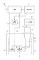
図1は、本発明の第1実施形態に係る超電導コイル装置を示した概略的な構成図である。   FIG. 1 is a schematic configuration diagram showing a superconducting coil device according to a first embodiment of the present invention.

図1に示すように、超電導コイル装置1は、超電導コイル2と、真空容器3と、冷凍機4と、電源5と、電圧計測部6と、電流制御部7と、ヒータ8と、ヒータ制御部9とを備える。   As shown in FIG. 1, a superconducting coil device 1 includes a superconducting coil 2, a vacuum vessel 3, a refrigerator 4, a power source 5, a voltage measuring unit 6, a current control unit 7, a heater 8, and heater control. Part 9.

超電導コイル2は、超電導テープ線11が巻回されて形成される。超電導テープ線11は、例えば金属系超電導線である。また、酸化物系の高温超電導線でもよい。高温超電導線材は、例えばビスマス系(例えば、Bi2223相型、Bi2212相型)、イットリウム系(例えば、YBCO系)、タリウム(Tl)系、水銀(Hg)系が用いられる。   Superconducting coil 2 is formed by winding superconducting tape wire 11. The superconducting tape wire 11 is, for example, a metallic superconducting wire. An oxide-based high-temperature superconducting wire may also be used. As the high-temperature superconducting wire, for example, bismuth (for example, Bi2223 phase, Bi2212 phase), yttrium (for example, YBCO), thallium (Tl), or mercury (Hg) is used.

真空容器3には、超電導コイル2が収容されており、この真空容器3によって超電導コイル2の雰囲気を真空状態に保持する。   The superconducting coil 2 is accommodated in the vacuum vessel 3, and the atmosphere of the superconducting coil 2 is maintained in a vacuum state by the vacuum vessel 3.

冷凍機4は、一段ステージ13と、二段ステージ14とを備え、多段式の冷却構造を有する。一段ステージ13と、二段ステージ14とは、真空容器3に収容された熱シールド容器15により断熱される。二段ステージ14は、冷却板16を介して超電導コイル2に熱的に接続される。また熱シールド容器15には、超電導コイル2が収容される。   The refrigerator 4 includes a first stage 13 and a second stage 14 and has a multistage cooling structure. The first stage 13 and the second stage 14 are insulated by the heat shield container 15 accommodated in the vacuum container 3. The two-stage stage 14 is thermally connected to the superconducting coil 2 via the cooling plate 16. Further, the superconducting coil 2 is accommodated in the heat shield container 15.

電源5は、超電導コイル2を励磁させる。電源5は、超電導コイル2の両端の電極部分に接続された電流リード17を介して超電導コイル2に電気的に接続される。電流リード17と真空容器3とは電気的に絶縁される。なお、電源5は超電導コイル2を励磁できるものであれば、どのようなものであってもよい。   The power source 5 excites the superconducting coil 2. The power source 5 is electrically connected to the superconducting coil 2 via current leads 17 connected to electrode portions at both ends of the superconducting coil 2. The current lead 17 and the vacuum vessel 3 are electrically insulated. The power source 5 may be any device as long as it can excite the superconducting coil 2.

電圧計測部6は、超電導コイル2の両端電圧を計測する。   The voltage measuring unit 6 measures the voltage across the superconducting coil 2.

また、電圧計測部6は、超電導コイル2の両端電圧が所定の閾値を超えたか否かを判定する異常検出器である。電圧計測部6は、超電導コイル2の両端電圧が所定の閾値を超えると、超電導コイル2が異常であると判断する。この所定の閾値は、超電導コイル2の形状や寸法、温度、超電導コイル2に供給される電流、超電導コイル2に印加される磁場、超電導テープ線11の材料によって決められる。   The voltage measuring unit 6 is an abnormality detector that determines whether or not the voltage across the superconducting coil 2 exceeds a predetermined threshold. The voltage measuring unit 6 determines that the superconducting coil 2 is abnormal when the voltage across the superconducting coil 2 exceeds a predetermined threshold. The predetermined threshold is determined by the shape and size of the superconducting coil 2, the temperature, the current supplied to the superconducting coil 2, the magnetic field applied to the superconducting coil 2, and the material of the superconducting tape wire 11.

さらに、電圧計測部6は、電流制御部7から超電導コイル2に供給される電流値を取得し、かつ、ヒータ制御部9から超電導コイル2の温度を取得する。電圧計測部6は、超電導コイル2の両端電圧と、超電導コイル2に供給される電流値と、超電導コイル2の温度とを定期的に記録する。電圧計測部6は、記録した電圧と電流と温度との関係が、所定の範囲を超えると、超電導コイル2が異常であると判断する。所定の範囲は、例えば、超電導コイル2の形状や寸法の公差、温度の計測誤差、超電導コイル2に供給される電流の計測誤差、超電導コイル2に印加される磁場の誤差などの種々の誤差要因によって決められる。また、超電導コイル2の両端電圧と、超電導コイル2に供給される電流値と、超電導コイル2の温度との記録から、統計的な手法によっても決められる。   Further, the voltage measuring unit 6 acquires the current value supplied from the current control unit 7 to the superconducting coil 2 and acquires the temperature of the superconducting coil 2 from the heater control unit 9. The voltage measuring unit 6 periodically records the voltage across the superconducting coil 2, the current value supplied to the superconducting coil 2, and the temperature of the superconducting coil 2. The voltage measuring unit 6 determines that the superconducting coil 2 is abnormal when the relationship between the recorded voltage, current, and temperature exceeds a predetermined range. The predetermined range includes various error factors such as tolerance of the shape and size of the superconducting coil 2, temperature measurement error, measurement error of the current supplied to the superconducting coil 2, and error of the magnetic field applied to the superconducting coil 2. It is decided by. It can also be determined by a statistical method from the records of the voltage across the superconducting coil 2, the current value supplied to the superconducting coil 2, and the temperature of the superconducting coil 2.

電流制御部7は、電圧計測部6から超電導コイル2の異常の有無の判断結果を取得する。電流制御部7は、この判断結果に基づいて超電導コイル2に流れる電流を制御する。例えば、電流制御部7は、電圧計測部6が超電導コイル2の異常を検出した場合には、電源5の出力電流を急激に低下、もしくは供給を遮断する。すなわち、電流制御部7は、超電導コイル2の保護部でもある。   The current control unit 7 acquires the determination result of the presence or absence of abnormality of the superconducting coil 2 from the voltage measurement unit 6. The current control unit 7 controls the current flowing through the superconducting coil 2 based on the determination result. For example, when the voltage measuring unit 6 detects an abnormality in the superconducting coil 2, the current control unit 7 rapidly decreases the output current of the power supply 5 or cuts off the supply. That is, the current control unit 7 is also a protection unit for the superconducting coil 2.

ヒータ8は、冷凍機4の二段ステージ14に設けられる。ヒータ8は、二段ステージ14および冷却板16を介して超電導コイル2の温度を上げる。ヒータ8は、ヒータ制御部9から供給される電力によって加熱される電気ヒータである。   The heater 8 is provided on the second stage 14 of the refrigerator 4. The heater 8 raises the temperature of the superconducting coil 2 via the two-stage stage 14 and the cooling plate 16. The heater 8 is an electric heater that is heated by electric power supplied from the heater control unit 9.

ヒータ制御部9は、ヒータ8を制御する。ヒータ8およびヒータ制御部9は超電導コイル2の加熱部である。   The heater control unit 9 controls the heater 8. The heater 8 and the heater control unit 9 are heating units for the superconducting coil 2.

超電導コイル装置1は、通常運転の場合には、冷凍機4によって、超電導コイル2の温度を制御する。具体的には、超電導コイル2が高温超電導コイルであれば、超電導コイル2の温度を略20Kに制御する。   The superconducting coil device 1 controls the temperature of the superconducting coil 2 by the refrigerator 4 in the normal operation. Specifically, if the superconducting coil 2 is a high-temperature superconducting coil, the temperature of the superconducting coil 2 is controlled to approximately 20K.

他方、超電導コイル装置1は、超電導コイル2の劣化等の異常の有無を検査する場合には、ヒータ8によって、超電導コイル2の温度を上げる。具体的には、超電導コイル2が高温超電導コイルであれば、超電導コイル2の温度を略20Kから略70Kまで変化させる。超電導コイル装置1は、超電導コイル2の温度を上げて、超電導コイル2に電流を通電し、超電導コイル2に発生した両端電圧を測定する。   On the other hand, the superconducting coil device 1 raises the temperature of the superconducting coil 2 by the heater 8 when inspecting the presence or absence of abnormality such as deterioration of the superconducting coil 2. Specifically, if the superconducting coil 2 is a high-temperature superconducting coil, the temperature of the superconducting coil 2 is changed from approximately 20K to approximately 70K. The superconducting coil device 1 raises the temperature of the superconducting coil 2, energizes the superconducting coil 2, and measures the voltage across the superconducting coil 2.

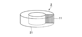
図2は、本発明の第1実施形態に係る超電導コイル装置の超電導コイルを示した概略的な構成図である。   FIG. 2 is a schematic configuration diagram showing the superconducting coil of the superconducting coil device according to the first embodiment of the present invention.

図2に示すように、超電導コイル2は、超電導テープ線11と、巻枠21とを備える。   As shown in FIG. 2, the superconducting coil 2 includes a superconducting tape wire 11 and a winding frame 21.

超電導テープ線11は、例えば、幅4.4mm、厚み0.2mmに形成される。   The superconducting tape wire 11 is formed to have a width of 4.4 mm and a thickness of 0.2 mm, for example.

巻枠21は、例えば、内径50mmに形成され、超電導テープ線11が86ターン巻回される。   The winding frame 21 is formed with an inner diameter of 50 mm, for example, and the superconducting tape wire 11 is wound 86 turns.

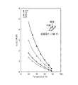
図3は、本発明の第1実施形態に係る超電導コイル装置に用いられる超電導テープ線の臨界電流の温度依存性の一例を示した図である。   FIG. 3 is a diagram showing an example of the temperature dependence of the critical current of the superconducting tape wire used in the superconducting coil device according to the first embodiment of the present invention.

また、図3は、超電導テープ線11の幅広面に対する磁場印加角度を90度としたときの磁場が0.5T、1.0T、2.0Tおよび3.0Tのそれぞれにおける臨界電流値Icを、温度が77Kにおける自己磁場中での臨界電流値Ic(77K、0T)で除した値Ic/Ic(77K、0T)の温度依存性を示している。   FIG. 3 shows the critical current values Ic when the magnetic field application angle with respect to the wide surface of the superconducting tape wire 11 is 90 degrees and the magnetic fields are 0.5T, 1.0T, 2.0T, and 3.0T, respectively. The temperature dependence of the value Ic / Ic (77K, 0T) divided by the critical current value Ic (77K, 0T) in a self magnetic field at a temperature of 77K is shown.

ここで、臨界電流値とは、超電導テープ線11に1μV/cmの電界が発生したときの電流値である。   Here, the critical current value is a current value when an electric field of 1 μV / cm is generated in the superconducting tape wire 11.

図3に示すように、超電導テープ線11は、磁場の強さが変わらなければ、温度が高いほど、臨界電流値が小さい。すなわち、超電導テープ線11は、温度が上昇するにしたがって臨界電流値が減少する特性を備える。   As shown in FIG. 3, the superconducting tape wire 11 has a smaller critical current value as the temperature is higher, unless the strength of the magnetic field is changed. That is, the superconducting tape wire 11 has a characteristic that the critical current value decreases as the temperature rises.

図4は、本発明の第1実施形態に係る超電導コイル装置の超電導コイルについて、臨界電流値と温度の関係の一例を示した図である。   FIG. 4 is a diagram showing an example of the relationship between the critical current value and the temperature for the superconducting coil of the superconducting coil device according to the first embodiment of the present invention.

図4に示すように、超電導コイル2は、温度が高いほど、臨界電流値が小さい。すなわち、超電導コイル2は、温度が上昇するにしたがって臨界電流値が減少する特性を備える。具体的には、超電導コイル2が高温超電導コイルであれば、超電導コイル2は、その温度が略20Kのときに臨界電流値が略386Aであり、その温度が略70Kのときは臨界電流値が略87Aである。   As shown in FIG. 4, the superconducting coil 2 has a smaller critical current value as the temperature is higher. That is, the superconducting coil 2 has a characteristic that the critical current value decreases as the temperature rises. Specifically, if the superconducting coil 2 is a high-temperature superconducting coil, the superconducting coil 2 has a critical current value of about 386 A when the temperature is about 20 K, and the critical current value when the temperature is about 70 K. It is approximately 87A.

超電導コイル装置1は、超電導コイル2の劣化等の異常の有無を検知するために、超電導コイル2に臨界電流付近まで電流を通電し、コイル電圧と所定の閾値とを比較する。超電導コイル装置1は、コイル電圧が所定の閾値よりも高ければ、超電導コイル2に劣化等の異常が有ると判定する。   The superconducting coil device 1 supplies a current to the superconducting coil 2 to the vicinity of the critical current in order to detect whether there is an abnormality such as deterioration of the superconducting coil 2, and compares the coil voltage with a predetermined threshold value. The superconducting coil device 1 determines that the superconducting coil 2 has an abnormality such as deterioration if the coil voltage is higher than a predetermined threshold.

また、超電導コイル装置1は、超電導コイル2の劣化等の異常の有無を検知するために、超電導コイル2の両端電圧と、超電導コイル2に供給される電流値と、超電導コイル2の温度とを定期的に記録する。超電導コイル装置1は、電圧と電流と温度との関係が、所定の範囲を超えると、超電導コイル2が異常であると判断する。   Further, the superconducting coil device 1 detects the voltage at both ends of the superconducting coil 2, the current value supplied to the superconducting coil 2, and the temperature of the superconducting coil 2 in order to detect the presence or absence of abnormality such as deterioration of the superconducting coil 2. Record regularly. Superconducting coil device 1 determines that superconducting coil 2 is abnormal when the relationship among voltage, current, and temperature exceeds a predetermined range.

ここで、超電導コイル装置1は、超電導コイル2の検査をする場合には、ヒータ8によって超電導コイル2を加熱する。超電導コイル2の温度が、例えば略70Kまで上昇すると、超電導コイル2の臨界電流値を減少できる。   Here, when the superconducting coil device 1 inspects the superconducting coil 2, the superconducting coil 2 is heated by the heater 8. When the temperature of the superconducting coil 2 rises to, for example, about 70K, the critical current value of the superconducting coil 2 can be reduced.

したがって、超電導コイル装置1によれば、超電導コイル2の異常を検出するために必要な電流値を減少することで、超電導テープ線11にかかる電磁力を減らし、また、異常電圧発生時には電流の供給を遮断する時間を短くできる。電流の供給を遮断する時間が短くなれば、超電導コイル2の検査時にコイルが焼損する危険性が少なくなる。   Therefore, according to the superconducting coil device 1, the electromagnetic force applied to the superconducting tape wire 11 is reduced by reducing the current value necessary for detecting the abnormality of the superconducting coil 2, and the current is supplied when an abnormal voltage occurs. The time to shut off can be shortened. If the time for interrupting the supply of current is shortened, the risk of the coil burning out during inspection of the superconducting coil 2 is reduced.

したがって、本実施形態の超電導コイル装置1によれば、超電導コイル2の両端電圧を測定して、簡便かつ安全に超電導コイル2の異常を検出できる。   Therefore, according to the superconducting coil device 1 of the present embodiment, the voltage across the superconducting coil 2 can be measured, and the abnormality of the superconducting coil 2 can be detected simply and safely.

[第2の実施形態]
本発明に係る超電導コイル装置および超電導コイルの検査方法の第2実施形態について、図5および図6を参照して説明する。
[Second Embodiment]
A second embodiment of a superconducting coil device and a superconducting coil inspection method according to the present invention will be described with reference to FIGS.

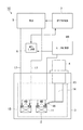
図5は、本発明の第2実施形態に係る超電導コイル装置を示した概略的な構成図である。   FIG. 5 is a schematic configuration diagram showing a superconducting coil device according to a second embodiment of the present invention.

本実施形態に係る超電導コイル装置1Aにおいて第1実施形態の超電導コイル装置1と同じ構成には同一の符号を付し、重複する説明は省略する。   In the superconducting coil device 1A according to the present embodiment, the same components as those of the superconducting coil device 1 of the first embodiment are denoted by the same reference numerals, and redundant description is omitted.

図5に示すように、超電導コイル装置1Aは、超電導コイル2と、真空容器3と、冷凍機4と、電源5と、電圧計測部6と、電流制御部7と、ヒータ8Aと、ヒータ制御部9Aとを備える。   As shown in FIG. 5, the superconducting coil device 1A includes a superconducting coil 2, a vacuum vessel 3, a refrigerator 4, a power source 5, a voltage measuring unit 6, a current control unit 7, a heater 8A, and heater control. Part 9A.

ヒータ8Aは、超電導コイル2に設けられる。ヒータ8Aは、超電導コイル2の温度を変化させる。   The heater 8A is provided in the superconducting coil 2. The heater 8 </ b> A changes the temperature of the superconducting coil 2.

ヒータ制御部9Aは、ヒータ8Aを制御する。ヒータ8Aおよびヒータ制御部9Aは超電導コイル2の加熱部である。   The heater control unit 9A controls the heater 8A. The heater 8 </ b> A and the heater control unit 9 </ b> A are heating units for the superconducting coil 2.

図6は、本発明の第2実施形態に係る超電導コイル装置の超電導コイルおよびヒータを示した概略的な構成図である。   FIG. 6 is a schematic configuration diagram showing a superconducting coil and a heater of the superconducting coil device according to the second embodiment of the present invention.

図6に示すように、超電導コイル装置1Aの超電導コイル2には、複数のヒータ8Aが設けられる。複数のヒータ8Aは、筒状に形成された超電導コイル2の底面22に、略同心円状に配置される。   As shown in FIG. 6, the superconducting coil 2 of the superconducting coil device 1A is provided with a plurality of heaters 8A. The plurality of heaters 8A are arranged substantially concentrically on the bottom surface 22 of the superconducting coil 2 formed in a cylindrical shape.

超電導コイル装置1Aは、超電導コイル2の劣化等の異常の有無を検査する場合には、いずれかのヒータ8Aを加熱する。そうすると、超電導コイル2は、部分的に温度が上昇する。すなわち、超電導コイル2の周方向に温度勾配が発生する。超電導コイル2のうち、温度が上昇した部分は、臨界電流値が下がるので、温度が上昇していない他の部分に比べて異常の検出に必要な電流値が減少する。そうすると、超電導コイル装置1Aは、超電導コイル2のうち、異常の有無を調べたい箇所の重み付けができる。このとき、超電導コイル2の両端電圧を測定すると、温度が上昇した部分が発生する電圧が支配的になる。   The superconducting coil device 1 </ b> A heats any of the heaters 8 </ b> A when inspecting whether there is an abnormality such as deterioration of the superconducting coil 2. As a result, the temperature of the superconducting coil 2 partially rises. That is, a temperature gradient is generated in the circumferential direction of the superconducting coil 2. Of the superconducting coil 2, the critical current value decreases in the portion where the temperature has increased, and therefore the current value necessary for detecting an abnormality decreases compared to other portions where the temperature has not increased. Then, the superconducting coil device 1A can weight the portion of the superconducting coil 2 where it is desired to check whether there is an abnormality. At this time, when the voltage between both ends of the superconducting coil 2 is measured, the voltage generated at the portion where the temperature has risen becomes dominant.

超電導テープ線11は、温度が上がるにしたがって臨界電流が減少する特性を持つ。このため、超電導コイル2の温度が変化すると、最大電圧が発生する超電導テープ線11の位置が異なることになる。   The superconducting tape wire 11 has a characteristic that the critical current decreases as the temperature rises. For this reason, when the temperature of the superconducting coil 2 changes, the position of the superconducting tape wire 11 where the maximum voltage is generated changes.

すなわち、超電導コイル装置1Aは、超電導コイル2内部の周方向に温度勾配を発生させて、超電導コイル2に電流を通電することで、超電導コイル2に発生する電圧の分布を変化させることが可能となる。   That is, the superconducting coil device 1 </ b> A can change the distribution of the voltage generated in the superconducting coil 2 by generating a temperature gradient in the circumferential direction inside the superconducting coil 2 and energizing the superconducting coil 2 with current. Become.

また、超電導コイル2内部の周方向に温度勾配を発生させて、超電導コイル2の両端電圧を測定することで、超電導テープ線11の一部で発生する電圧が超電導コイル2の両端電圧に占める割合を変化させることが可能となる。そうすると、順次に超電導コイル2の加熱位置を変更することで、異常のある箇所を容易に特定できる。   Further, the ratio of the voltage generated at a part of the superconducting tape wire 11 to the voltage at both ends of the superconducting coil 2 by measuring the voltage at both ends of the superconducting coil 2 by generating a temperature gradient in the circumferential direction inside the superconducting coil 2. Can be changed. If it does so, an abnormal location can be specified easily by changing the heating position of superconducting coil 2 one by one.

したがって、本実施形態の超電導コイル装置1Aによれば、超電導コイル2の両端電圧を測定して、簡便かつ安全に超電導コイル2の異常を検出できる。   Therefore, according to 1 A of the superconducting coil apparatus of this embodiment, the abnormality of the superconducting coil 2 can be detected simply and safely by measuring the voltage across the superconducting coil 2.

[第3の実施形態]
本発明に係る超電導コイル装置および超電導コイルの検査方法の第3実施形態について、図7から図8を参照して説明する。
[Third Embodiment]
A superconducting coil device and a superconducting coil inspection method according to a third embodiment of the present invention will be described with reference to FIGS.

図7は、本発明の第3実施形態に係る超電導コイル装置を示した概略的な構成図である。   FIG. 7 is a schematic configuration diagram illustrating a superconducting coil device according to a third embodiment of the present invention.

本実施形態に係る超電導コイル装置1Bにおいて第1実施形態の超電導コイル装置1と同じ構成には同一の符号を付し、重複する説明は省略する。   In the superconducting coil device 1B according to the present embodiment, the same components as those of the superconducting coil device 1 according to the first embodiment are denoted by the same reference numerals, and redundant description is omitted.

図7に示すように、超電導コイル装置1Bは、超電導コイル2Aと、真空容器3と、冷凍機4と、電源5と、電圧計測部6と、電流制御部7と、ヒータ8と、ヒータ制御部9とを備える。   As shown in FIG. 7, the superconducting coil device 1B includes a superconducting coil 2A, a vacuum vessel 3, a refrigerator 4, a power source 5, a voltage measuring unit 6, a current control unit 7, a heater 8, and heater control. Part 9.

超電導コイル2Aは、超電導テープ線11Aが巻回されて形成される。超電導テープ線11Aは、例えば、酸化物系の高温超電導線である。高温超電導線材は、例えばイットリウム系(例えば、YBCO系)が用いられる。   Superconducting coil 2A is formed by winding superconducting tape wire 11A. The superconducting tape wire 11A is, for example, an oxide-based high-temperature superconducting wire. As the high-temperature superconducting wire, for example, yttrium (for example, YBCO) is used.

図8は、本発明の第3実施形態に係る超電導コイル装置の超電導コイルを示した概略的な構成図である。   FIG. 8 is a schematic configuration diagram showing a superconducting coil of the superconducting coil device according to the third embodiment of the present invention.

図8に示すように、超電導コイル2Aは、超電導テープ線11Aと、巻枠21とを備える。   As shown in FIG. 8, the superconducting coil 2 </ b> A includes a superconducting tape wire 11 </ b> A and a winding frame 21.

超電導テープ線11Aは、例えば、幅4.4mm、厚み0.2mmに形成される。   The superconducting tape wire 11A is formed to have a width of 4.4 mm and a thickness of 0.2 mm, for example.

巻枠21は、例えば、内径50mmに形成され、超電導テープ線11Aが86ターン巻回される。   The winding frame 21 is formed with an inner diameter of 50 mm, for example, and the superconducting tape wire 11A is wound 86 turns.

図9は、本発明の第3実施形態に係る超電導コイル装置に用いられる超電導テープ線の臨界電流の磁場依存性の一例を示した図である。   FIG. 9 is a diagram showing an example of the magnetic field dependence of the critical current of the superconducting tape wire used in the superconducting coil device according to the third embodiment of the present invention.

図9は、超電導テープ線11Aの温度が40K、60Kおよび70Kのそれぞれにおいて、超電導テープ線11Aの幅広面に対する磁場印加角度を0度または90度としたときの臨界電流値Icを、温度が77Kにおける自己磁場中での臨界電流値Ic(77K、0T)で除した値Ic/Ic(77K、0T)の磁場依存性を示している。   FIG. 9 shows the critical current value Ic when the temperature of the superconducting tape wire 11A is 40K, 60K, and 70K, and the magnetic field application angle with respect to the wide surface of the superconducting tape wire 11A is 0 degree or 90 degrees. Shows the magnetic field dependence of the value Ic / Ic (77K, 0T) divided by the critical current value Ic (77K, 0T) in the self-magnetic field.

図9に示すように、超電導テープ線11Aは、温度が高いほど、磁場印加角度の依存性が小さい。すなわち、超電導テープ線11Aは、温度が上がるにしたがって臨界電流の磁場角度依存性が減少する特性を備える。   As shown in FIG. 9, the superconducting tape wire 11A is less dependent on the magnetic field application angle as the temperature is higher. That is, the superconducting tape wire 11A has a characteristic that the dependence of the critical current on the magnetic field angle decreases as the temperature increases.

図10から図12は、本発明の第3実施形態に係る超電導コイル装置の超電導コイルについて、各ターンに発生する電圧と超電導コイルの温度との関係を示した図である。図10は、超電導コイルの温度が20Kの場合を示した図である。また、図11は、超電導コイルの温度が60Kの場合を示した図である。さらに、図12は、超電導コイルの温度が70Kの場合を示した図である。   10 to 12 are diagrams showing the relationship between the voltage generated at each turn and the temperature of the superconducting coil in the superconducting coil of the superconducting coil device according to the third embodiment of the present invention. FIG. 10 is a diagram showing a case where the temperature of the superconducting coil is 20K. FIG. 11 is a diagram showing a case where the temperature of the superconducting coil is 60K. Further, FIG. 12 is a diagram showing a case where the temperature of the superconducting coil is 70K.

なお、超電導コイル2Aの各ターンに発生した電圧は、最大電圧が発生したターンの電圧を代表値として正規化した値である。また、超電導コイル2Aの最内層の超電導テープ線11Aを1ターン目とする。   The voltage generated at each turn of the superconducting coil 2A is a value normalized with the voltage of the turn at which the maximum voltage is generated as a representative value. Further, the superconducting tape wire 11A in the innermost layer of the superconducting coil 2A is defined as the first turn.

図10に示すように、超電導コイル2Aの温度が20Kの場合には、超電導テープ線11Aの37ターン目で最大電圧が発生した。   As shown in FIG. 10, when the temperature of the superconducting coil 2A was 20K, the maximum voltage was generated at the 37th turn of the superconducting tape wire 11A.

また、図11に示すように、超電導コイル2Aの温度が60Kの場合には、超電導テープ線11Aの23ターン目で最大電圧が発生した。   Further, as shown in FIG. 11, when the temperature of the superconducting coil 2A was 60K, the maximum voltage was generated at the 23rd turn of the superconducting tape wire 11A.

さらに、図12に示すように、超電導コイル2Aの温度が70Kの場合には、超電導テープ線11Aの1ターン目で最大電圧が発生した。   Furthermore, as shown in FIG. 12, when the temperature of the superconducting coil 2A was 70K, the maximum voltage was generated at the first turn of the superconducting tape wire 11A.

超電導コイル2Aに電流を通電すると、超電導テープ線11Aの各ターンに磁場が印加されて超電導コイル2Aに電圧が発生する。このとき、超電導コイル2Aに発生する磁場の勾配の影響によって、超電導テープ線11Aの各ターンが受ける磁場の大きさおよび角度は異なる。したがって、超電導テープ線11Aの各ターンが発生する電圧は異なることになる。超電導コイル2Aの両端電圧を測定すると、超電導テープ線11Aのうち、最大電圧が発生するターン付近の電圧が支配的になる。   When a current is passed through the superconducting coil 2A, a magnetic field is applied to each turn of the superconducting tape wire 11A, and a voltage is generated in the superconducting coil 2A. At this time, the magnitude and angle of the magnetic field received by each turn of the superconducting tape wire 11A differ due to the influence of the gradient of the magnetic field generated in the superconducting coil 2A. Therefore, the voltage generated by each turn of the superconducting tape wire 11A is different. When the voltage across the superconducting coil 2A is measured, the voltage near the turn where the maximum voltage is generated in the superconducting tape wire 11A becomes dominant.

超電導テープ線11Aは、温度が上がるにしたがって臨界電流の磁場角度依存性が減少する特性を持つ。このため、超電導コイル2Aの温度が変化すると、最大電圧が発生する超電導テープ線11Aのターン位置が異なることになる。   The superconducting tape wire 11A has a characteristic that the dependence of the critical current on the magnetic field angle decreases as the temperature increases. For this reason, when the temperature of the superconducting coil 2A changes, the turn position of the superconducting tape wire 11A where the maximum voltage is generated is different.

すなわち、超電導コイル装置1Bは、超電導コイル2Aの温度を変化させて、超電導コイル2Aに電流を通電することで、超電導コイル2Aに発生する電圧の分布を変化させることが可能となる。   That is, the superconducting coil device 1B can change the distribution of the voltage generated in the superconducting coil 2A by changing the temperature of the superconducting coil 2A and passing a current through the superconducting coil 2A.

また、超電導コイル2Aの温度を変化させて、超電導コイル2Aの両端電圧を測定することで、超電導テープ線11Aの各ターンで発生する電圧が超電導コイル2Aの両端電圧に占める割合を変化させることが可能となる。   Further, by changing the temperature of the superconducting coil 2A and measuring the voltage across the superconducting coil 2A, the ratio of the voltage generated at each turn of the superconducting tape wire 11A to the voltage across the superconducting coil 2A can be changed. It becomes possible.

したがって、本実施形態の超電導コイル装置1Bによれば、超電導コイル2Aの両端電圧を測定して、簡便かつ安全に超電導コイル2Aの異常を検出できる。   Therefore, according to the superconducting coil device 1B of the present embodiment, the voltage across the superconducting coil 2A can be measured, and the abnormality of the superconducting coil 2A can be detected simply and safely.

[第4の実施形態]
本発明に係る超電導コイル装置および超電導コイルの検査方法の第4実施形態について、図13から図14を参照して説明する。
[Fourth Embodiment]
A superconducting coil device and a superconducting coil inspection method according to a fourth embodiment of the present invention will be described with reference to FIGS.

図13は、本発明の第4実施形態に係る超電導コイル装置を示した概略的な構成図である。   FIG. 13 is a schematic configuration diagram illustrating a superconducting coil device according to a fourth embodiment of the present invention.

本実施形態に係る超電導コイル装置1Cにおいて第1実施形態の超電導コイル装置1と同じ構成には同一の符号を付し、重複する説明は省略する。   In the superconducting coil device 1C according to the present embodiment, the same components as those of the superconducting coil device 1 according to the first embodiment are denoted by the same reference numerals, and redundant description is omitted.

図13に示すように、超電導コイル装置1Cは、超電導コイル2と、真空容器3と、冷凍機4と、電源5と、電圧計測部6と、電流制御部7と、ヒータ8Bと、ヒータ制御部9Bとを備える。   As shown in FIG. 13, the superconducting coil device 1C includes a superconducting coil 2, a vacuum vessel 3, a refrigerator 4, a power source 5, a voltage measuring unit 6, a current control unit 7, a heater 8B, and heater control. Part 9B.

ヒータ8Bは、超電導コイル2に設けられる。ヒータ8Bは、超電導コイル2の温度を変化させる。   The heater 8B is provided in the superconducting coil 2. The heater 8B changes the temperature of the superconducting coil 2.

ヒータ制御部9Bは、ヒータ8Bを制御する。ヒータ8Bおよびヒータ制御部9Bは超電導コイル2の加熱部である。   The heater control unit 9B controls the heater 8B. The heater 8B and the heater control unit 9B are heating units for the superconducting coil 2.

図14は、本発明の第4実施形態に係る超電導コイル装置の超電導コイルおよびヒータを示した概略的な構成図である。   FIG. 14 is a schematic configuration diagram showing a superconducting coil and a heater of a superconducting coil device according to the fourth embodiment of the present invention.

図14に示すように、超電導コイル装置1Cのヒータ8Bは、内周側ヒータ24と、外周側ヒータ25とを備える。内周側ヒータ24は、筒状に形成された超電導コイル2の底面22であって、内周の周縁に偏倚させて設けられる。外周側ヒータ25は、筒状に形成された超電導コイル2の底面22であって、外周の周縁に偏倚させて設けられる。   As shown in FIG. 14, the heater 8 </ b> B of the superconducting coil device 1 </ b> C includes an inner peripheral heater 24 and an outer peripheral heater 25. The inner peripheral heater 24 is a bottom surface 22 of the superconducting coil 2 formed in a cylindrical shape, and is provided biased to the inner peripheral edge. The outer peripheral side heater 25 is a bottom surface 22 of the superconducting coil 2 formed in a cylindrical shape, and is provided biased to the outer peripheral edge.

内周側ヒータ24および外周側ヒータ25は、ヒータ制御部9Bに接続される。   The inner peripheral heater 24 and the outer peripheral heater 25 are connected to the heater control unit 9B.

超電導コイル装置1Cは、超電導コイル2の劣化等の異常の有無を検査する場合には、ヒータ8Bによって、超電導コイル2の温度を変化させる。具体的には、ヒータ8Bは、内周側ヒータ24と外周側ヒータ25との温度差によって超電導コイル2内部の内周側と外周側との間、すなわち径方向に温度勾配を発生させる。超電導コイル装置1Cは、超電導コイル2内部の径方向に温度勾配を発生させて、超電導コイル2に電流を通電し、超電導コイル2に発生した両端電圧を測定する。   The superconducting coil device 1C changes the temperature of the superconducting coil 2 by the heater 8B when inspecting the presence or absence of abnormality such as deterioration of the superconducting coil 2. Specifically, the heater 8B generates a temperature gradient between the inner peripheral side and the outer peripheral side in the superconducting coil 2 due to the temperature difference between the inner peripheral heater 24 and the outer peripheral heater 25, that is, in the radial direction. The superconducting coil device 1 </ b> C generates a temperature gradient in the radial direction inside the superconducting coil 2, energizes the superconducting coil 2, and measures the voltage across the superconducting coil 2.

超電導コイル2に電流を通電すると、超電導テープ線11の各ターンに磁場が印加されて超電導コイル2に電圧が発生する。このとき、超電導コイル2に発生する磁場の勾配の影響によって、超電導テープ線11の各ターンが受ける磁場の大きさおよび角度が異なる。したがって、超電導テープ線11の各ターンが発生する電圧は異なることになる。超電導コイル2の両端電圧を測定すると、超電導テープ線11のうち、最大電圧が発生するターン付近の電圧が支配的になる。   When a current is passed through the superconducting coil 2, a magnetic field is applied to each turn of the superconducting tape wire 11 and a voltage is generated in the superconducting coil 2. At this time, the magnitude and angle of the magnetic field received by each turn of the superconducting tape wire 11 differ depending on the influence of the gradient of the magnetic field generated in the superconducting coil 2. Therefore, the voltage generated by each turn of the superconducting tape wire 11 is different. When the voltage at both ends of the superconducting coil 2 is measured, the voltage near the turn where the maximum voltage is generated in the superconducting tape wire 11 becomes dominant.

ここで、超電導テープ線11は、磁場角度依存性に関わらず、温度が上がるにしたがって臨界電流が減少する特性を持つ。このため、超電導コイル2内部の径方向に適宜に温度勾配を加えると、超電導テープ線11の各ターンに発生する電圧の差を小さくしたり大きくしたりできる。   Here, the superconducting tape wire 11 has a characteristic that the critical current decreases as the temperature rises regardless of the magnetic field angle dependency. For this reason, when a temperature gradient is appropriately applied in the radial direction inside the superconducting coil 2, the difference in voltage generated at each turn of the superconducting tape wire 11 can be reduced or increased.

すなわち、超電導コイル装置1Cは、超電導コイル2内部の径方向に温度勾配を加えて、超電導コイル2に電流を通電することで、超電導テープ線11の各ターンで発生する電圧が超電導コイル2の両端電圧に占める割合を略均等にすることが可能となる。   That is, the superconducting coil device 1C applies a temperature gradient in the radial direction inside the superconducting coil 2 and energizes the superconducting coil 2 so that the voltage generated at each turn of the superconducting tape wire 11 is applied to both ends of the superconducting coil 2. It becomes possible to make the proportion of the voltage approximately equal.

また、超電導コイル装置1Cは、超電導コイル2内部の径方向に温度勾配を加えて、超電導コイル2に電流を通電することで、超電導テープ線11のいずれかのターンで発生する電圧を、超電導コイル2の両端電圧に占める最大の割合にすることが可能となる。   Also, the superconducting coil device 1C applies a temperature gradient in the radial direction inside the superconducting coil 2 and energizes the superconducting coil 2 to generate a voltage generated at any turn of the superconducting tape wire 11. It becomes possible to make it the maximum ratio which occupies for the voltage of both ends of 2.

したがって、本実施形態の超電導コイル装置1Cによれば、超電導コイル2の両端電圧を測定して、簡便かつ安全に超電導コイル2の異常を検出できる。   Therefore, according to the superconducting coil device 1C of this embodiment, the voltage across the superconducting coil 2 can be measured, and the abnormality of the superconducting coil 2 can be detected simply and safely.

[第5の実施形態]
本発明に係る超電導コイル装置および超電導コイルの検査方法の第5実施形態について、図15を参照して説明する。
[Fifth Embodiment]
A fifth embodiment of a superconducting coil device and a superconducting coil inspection method according to the present invention will be described with reference to FIG.

図15は、本発明の第5実施形態に係る超電導コイル装置を示した概略的な構成図である。   FIG. 15 is a schematic configuration diagram illustrating a superconducting coil device according to a fifth embodiment of the present invention.

本実施形態に係る超電導コイル装置1Dにおいて第1実施形態の超電導コイル装置1と同じ構成には同一の符号を付し、重複する説明は省略する。   In the superconducting coil device 1D according to the present embodiment, the same components as those of the superconducting coil device 1 of the first embodiment are denoted by the same reference numerals, and redundant description is omitted.

図15に示すように、超電導コイル装置1Dは、超電導コイル2と、真空容器3と、冷凍機4と、電源5と、電圧計測部6と、電流制御部7と、磁場発生コイル27と、磁場発生コイル制御部28とを備える。   As shown in FIG. 15, the superconducting coil device 1D includes a superconducting coil 2, a vacuum container 3, a refrigerator 4, a power source 5, a voltage measuring unit 6, a current control unit 7, a magnetic field generating coil 27, And a magnetic field generating coil controller 28.

磁場発生コイル27は、真空容器3に収容される。磁場発生コイル27は、超電導コイル2の周囲に複数、例えば超電導コイル2を挟んで2つ設けられる。磁場発生コイル27は、超電導コイル2の周囲に磁場を印加する。磁場発生コイル27は、一様な強さの磁場や、適宜に強さが分布した磁場を発生する。磁場発生コイル27には、超電導コイルを用いることができる。   The magnetic field generating coil 27 is accommodated in the vacuum vessel 3. A plurality of magnetic field generating coils 27 are provided around the superconducting coil 2, for example, two sandwiching the superconducting coil 2. The magnetic field generating coil 27 applies a magnetic field around the superconducting coil 2. The magnetic field generating coil 27 generates a magnetic field having a uniform strength or a magnetic field with appropriate strength distribution. A superconducting coil can be used as the magnetic field generating coil 27.

磁場発生コイル制御部28は、磁場発生コイル27を制御する。   The magnetic field generation coil control unit 28 controls the magnetic field generation coil 27.

他方、超電導コイル装置1Dは、超電導コイル2の劣化等の異常の有無を検査する場合には、磁場発生コイル27によって、超電導コイル2に磁場を印加する。   On the other hand, the superconducting coil device 1D applies a magnetic field to the superconducting coil 2 by the magnetic field generating coil 27 when inspecting the presence / absence of abnormality such as deterioration of the superconducting coil 2.

超電導コイル2の劣化等の異常の有無を検出するためには、超電導コイル2に臨界電流付近まで電流を通電し、コイル電圧と所定の閾値とを比較する。コイル電圧が所定の閾値よりも高ければ、超電導コイル2の劣化等の異常が有ると判定する。   In order to detect the presence or absence of abnormality such as deterioration of the superconducting coil 2, a current is passed through the superconducting coil 2 to near the critical current, and the coil voltage is compared with a predetermined threshold value. If the coil voltage is higher than a predetermined threshold, it is determined that there is an abnormality such as deterioration of the superconducting coil 2.

ここで、超電導コイル装置1Dは、超電導コイル2の検査をする場合には、磁場発生コイル27によって超電導コイル2に磁場を印加する。超電導コイル2に磁場が印加されると、超電導コイル2の臨界電流値を減少できる。   Here, the superconducting coil device 1 </ b> D applies a magnetic field to the superconducting coil 2 by the magnetic field generating coil 27 when inspecting the superconducting coil 2. When a magnetic field is applied to the superconducting coil 2, the critical current value of the superconducting coil 2 can be reduced.

したがって、超電導コイル装置1Dによれば、超電導コイル2の劣化等の異常を検出するために必要な電流値を減少することで、異常電圧発生時には電流の供給を遮断する時間を短くできる。電流の供給を遮断する時間が短くなれば、超電導コイル2の検査時にコイルが焼損する危険性が少なくなる。   Therefore, according to the superconducting coil device 1D, by reducing the current value necessary for detecting an abnormality such as deterioration of the superconducting coil 2, it is possible to shorten the time for interrupting the supply of current when an abnormal voltage occurs. If the time for interrupting the supply of current is shortened, the risk of the coil burning out during inspection of the superconducting coil 2 is reduced.

また、超電導コイル装置1Dは、磁場発生コイル27によって超電導コイル2に適宜に強さが分布した磁場を印加する。そうすると、印加された磁場の強さに応じて、超電導コイル2の臨界電流値も超電導コイル2内で分布する。   In addition, the superconducting coil device 1D applies a magnetic field whose intensity is appropriately distributed to the superconducting coil 2 by the magnetic field generating coil 27. Then, the critical current value of the superconducting coil 2 is also distributed in the superconducting coil 2 according to the strength of the applied magnetic field.

すなわち、超電導コイル装置1Dは、超電導コイル2に適宜に強さが分布した磁場を印加して、超電導コイル2に電流を通電することで、超電導テープ線11の各ターンで発生する電圧が超電導コイル2の両端電圧に占める割合を略均等にすることが可能となる。   That is, the superconducting coil device 1D applies a magnetic field having an appropriately distributed intensity to the superconducting coil 2 and energizes the superconducting coil 2 so that the voltage generated at each turn of the superconducting tape wire 11 is superconducting coil. It is possible to make the ratio of the voltage at both ends of 2 substantially equal.

また、超電導コイル装置1Dは、超電導コイル2に適宜に強さが分布した磁場を印加して、超電導コイル2に電流を通電することで、超電導テープ線11のいずれかの箇所で発生する電圧を、超電導コイル2の両端電圧に占める最大の割合にすることが可能となる。   In addition, the superconducting coil device 1D applies a magnetic field with appropriately distributed strength to the superconducting coil 2 and energizes the superconducting coil 2 to generate a voltage generated at any location of the superconducting tape wire 11. It is possible to make the maximum ratio of the voltage across the superconducting coil 2.

したがって、本実施形態の超電導コイル装置1Dによれば、超電導コイル2の両端電圧を測定して、簡便かつ安全に超電導コイル2の異常を検出できる。   Therefore, according to the superconducting coil device 1D of this embodiment, the voltage across the superconducting coil 2 can be measured, and the abnormality of the superconducting coil 2 can be detected simply and safely.

[第6の実施形態]
本発明に係る超電導コイル装置および超電導コイルの検査方法の第6実施形態について、図16を参照して説明する。
[Sixth Embodiment]
A sixth embodiment of the superconducting coil device and superconducting coil inspection method according to the present invention will be described with reference to FIG.

図16は、本発明の第6実施形態に係る超電導コイル装置を示した概略的な構成図である。   FIG. 16 is a schematic configuration diagram illustrating a superconducting coil device according to a sixth embodiment of the present invention.

本実施形態に係る超電導コイル装置1Eにおいて第1実施形態の超電導コイル装置1と同じ構成には同一の符号を付し、重複する説明は省略する。   In the superconducting coil device 1E according to the present embodiment, the same components as those in the superconducting coil device 1 according to the first embodiment are denoted by the same reference numerals, and redundant description is omitted.

図16に示すように、超電導コイル装置1Eは、超電導コイル群30と、真空容器3と、冷凍機4と、電源5と、電圧計測部6と、電流制御部7とを備える。   As shown in FIG. 16, the superconducting coil device 1 </ b> E includes a superconducting coil group 30, a vacuum vessel 3, a refrigerator 4, a power source 5, a voltage measuring unit 6, and a current control unit 7.

超電導コイル群30は、複数の超電導コイル2を備える。複数の超電導コイル2は、例えばトロイダル状に配置される。また、マルチポール状に配置しても良い。   The superconducting coil group 30 includes a plurality of superconducting coils 2. The plurality of superconducting coils 2 are arranged in a toroidal shape, for example. Further, it may be arranged in a multipole shape.

超電導コイル2の劣化等の異常の有無を検出するためには、超電導コイル2に臨界電流付近まで電流を通電し、コイル電圧と所定の閾値とを比較する。コイル電圧が所定の閾値よりも高ければ、超電導コイル2の劣化等の異常が有ると判定する。   In order to detect the presence or absence of abnormality such as deterioration of the superconducting coil 2, a current is passed through the superconducting coil 2 to near the critical current, and the coil voltage is compared with a predetermined threshold value. If the coil voltage is higher than a predetermined threshold, it is determined that there is an abnormality such as deterioration of the superconducting coil 2.

ここで、超電導コイル装置1Eは、超電導コイル2の検査をする場合には、超電導コイル群30から、検査の対象となる1つ以上、全数未満の超電導コイル2を選択する。なお、超電導コイル群30はN個の超電導コイル2を備え、検査の対象となる超電導コイル2をM個選択するものとして説明する。なおN個>M個の関係がある。   Here, when the superconducting coil device 1 </ b> E inspects the superconducting coil 2, the superconducting coil group 30 selects one or more superconducting coils 2 to be inspected from the superconducting coil group 30. It is assumed that the superconducting coil group 30 includes N superconducting coils 2 and selects M superconducting coils 2 to be inspected. There are N> M relationships.

電流制御部7は、超電導コイル2の検査をする場合には、(N−M)個の超電導コイル2(磁場発生用の超電導コイル2)に電流を通電して、M個の超電導コイル2(検査対象の超電導コイル2)に磁場を印加する。M個の超電導コイル2は、磁場が印加されると、臨界電流値が減少する。   When inspecting the superconducting coils 2, the current control unit 7 supplies current to the (N−M) superconducting coils 2 (superconducting coils 2 for generating a magnetic field), and M superconducting coils 2 ( A magnetic field is applied to the superconducting coil 2) to be inspected. When the magnetic field is applied to the M superconducting coils 2, the critical current value decreases.

したがって、超電導コイル装置1Eによれば、超電導コイル2の劣化等の異常を検出するために必要な電流値を減少することで、異常電圧発生時には電流の供給を遮断する時間を短くできる。電流の供給を遮断する時間が短くなれば、超電導コイル2の検査時にコイルが焼損する危険性が少なくなる。   Therefore, according to the superconducting coil device 1E, by reducing the current value necessary for detecting an abnormality such as deterioration of the superconducting coil 2, it is possible to shorten the time for interrupting the supply of current when an abnormal voltage occurs. If the time for interrupting the supply of current is shortened, the risk of the coil burning out during inspection of the superconducting coil 2 is reduced.

また、超電導コイル装置1Eは、(N−M)個の超電導コイル2(磁場発生用の超電導コイル2)によってM個の超電導コイル2(検査対象の超電導コイル2)に適宜に強さが分布した磁場を印加する。そうすると、M個の超電導コイル2(検査対象の超電導コイル2)の臨界電流値は、印加された磁場の強さに応じて、それぞれの超電導コイル2内で分布する。   Further, in the superconducting coil device 1E, the strength is appropriately distributed to M superconducting coils 2 (superconducting coils 2 to be inspected) by (N−M) superconducting coils 2 (superconducting coils 2 for generating a magnetic field). Apply a magnetic field. Then, the critical current value of the M superconducting coils 2 (superconducting coils 2 to be inspected) is distributed in each superconducting coil 2 according to the strength of the applied magnetic field.

すなわち、超電導コイル装置1Eは、超電導コイル2に適宜に強さが分布した磁場を印加して、超電導コイル2に電流を通電することで、超電導テープ線11の各ターンで発生する電圧が超電導コイル2の両端電圧に占める割合を略均等にすることが可能となる。   That is, the superconducting coil device 1E applies a magnetic field with appropriately distributed strength to the superconducting coil 2 and energizes the superconducting coil 2 so that the voltage generated at each turn of the superconducting tape wire 11 is superconducting coil. It is possible to make the ratio of the voltage at both ends of 2 substantially equal.

また、超電導コイル装置1Eは、超電導コイル2に適宜に強さが分布した磁場を印加して、超電導コイル2に電流を通電することで、超電導テープ線11のいずれかの箇所で発生する電圧を、超電導コイル2の両端電圧に占める最大の割合にすることが可能となる。   In addition, the superconducting coil device 1E applies a magnetic field with appropriately distributed strength to the superconducting coil 2 and applies a current to the superconducting coil 2, thereby generating a voltage generated at any location of the superconducting tape wire 11. It is possible to make the maximum ratio of the voltage across the superconducting coil 2.

したがって、本実施形態の超電導コイル装置1Eによれば、超電導コイル2の両端電圧を測定して、簡便かつ安全に超電導コイル2の異常を検出できる。   Therefore, according to the superconducting coil device 1E of this embodiment, the voltage across the superconducting coil 2 can be measured, and the abnormality of the superconducting coil 2 can be detected simply and safely.

本発明の第1実施形態に係る超電導コイル装置を示した概略的な構成図。The schematic block diagram which showed the superconducting coil apparatus which concerns on 1st Embodiment of this invention. 本発明の第1実施形態に係る超電導コイル装置の超電導コイルを示した概略的な構成図。The schematic block diagram which showed the superconducting coil of the superconducting coil apparatus which concerns on 1st Embodiment of this invention. 本発明の第1実施形態に係る超電導コイル装置に用いられる超電導テープ線の臨界電流の温度依存性の一例を示した図。The figure which showed an example of the temperature dependence of the critical current of the superconducting tape wire used for the superconducting coil apparatus which concerns on 1st Embodiment of this invention. 本発明の第1実施形態に係る超電導コイル装置の超電導コイルについて、臨界電流値と温度の関係の一例を示した図。The figure which showed an example of the relationship between a critical current value and temperature about the superconducting coil of the superconducting coil apparatus which concerns on 1st Embodiment of this invention. 本発明の第2実施形態に係る超電導コイル装置を示した概略的な構成図。The schematic block diagram which showed the superconducting coil apparatus which concerns on 2nd Embodiment of this invention. 本発明の第2実施形態に係る超電導コイル装置の超電導コイルおよびヒータを示した概略的な構成図。The schematic block diagram which showed the superconducting coil and heater of the superconducting coil apparatus which concern on 2nd Embodiment of this invention. 本発明の第3実施形態に係る超電導コイル装置を示した概略的な構成図。The schematic block diagram which showed the superconducting coil apparatus which concerns on 3rd Embodiment of this invention. 本発明の第3実施形態に係る超電導コイル装置の超電導コイルを示した概略的な構成図。The schematic block diagram which showed the superconducting coil of the superconducting coil apparatus which concerns on 3rd Embodiment of this invention. 本発明の第3実施形態に係る超電導コイル装置に用いられる超電導テープ線の臨界電流の磁場依存性の一例を示した図。The figure which showed an example of the magnetic field dependence of the critical current of the superconducting tape wire used for the superconducting coil apparatus which concerns on 3rd Embodiment of this invention. 本発明の第3実施形態に係る超電導コイル装置の超電導コイルについて、各ターンに発生する電圧と超電導コイルの温度との関係を示した図。The figure which showed the relationship between the voltage which generate | occur | produces in each turn, and the temperature of a superconducting coil about the superconducting coil of the superconducting coil apparatus which concerns on 3rd Embodiment of this invention. 本発明の第3実施形態に係る超電導コイル装置の超電導コイルについて、各ターンに発生する電圧と超電導コイルの温度との関係を示した図。The figure which showed the relationship between the voltage which generate | occur | produces in each turn, and the temperature of a superconducting coil about the superconducting coil of the superconducting coil apparatus which concerns on 3rd Embodiment of this invention. 本発明の第3実施形態に係る超電導コイル装置の超電導コイルについて、各ターンに発生する電圧と超電導コイルの温度との関係を示した図。The figure which showed the relationship between the voltage which generate | occur | produces in each turn, and the temperature of a superconducting coil about the superconducting coil of the superconducting coil apparatus which concerns on 3rd Embodiment of this invention. 本発明の第4実施形態に係る超電導コイル装置を示した概略的な構成図。The schematic block diagram which showed the superconducting coil apparatus which concerns on 4th Embodiment of this invention. 本発明の第4実施形態に係る超電導コイル装置の超電導コイルおよびヒータを示した概略的な構成図。The schematic block diagram which showed the superconducting coil and heater of the superconducting coil apparatus which concern on 4th Embodiment of this invention. 本発明の第5実施形態に係る超電導コイル装置を示した概略的な構成図。The schematic block diagram which showed the superconducting coil apparatus which concerns on 5th Embodiment of this invention. 本発明の第6実施形態に係る超電導コイル装置を示した概略的な構成図。The schematic block diagram which showed the superconducting coil apparatus which concerns on 6th Embodiment of this invention.

符号の説明Explanation of symbols

1、1A、1B、1C、1D、1E 超電導コイル装置
2、2A 超電導コイル
3 真空容器
4 冷凍機
5 電源
6 電圧計測部
7 電流制御部
8、8A、8B ヒータ
9、9A、9B ヒータ制御部
11、11A 超電導テープ線
13 一段ステージ
14 二段ステージ
15 熱シールド容器
16 冷却板
17 電流リード
21 巻枠
22 底面
24 内周側ヒータ
25 外周側ヒータ
27 磁場発生コイル
28 磁場発生コイル制御部
30 超電導コイル群
1, 1A, 1B, 1C, 1D, 1E Superconducting coil device 2, 2A Superconducting coil 3 Vacuum container 4 Refrigerator 5 Power supply 6 Voltage measuring unit 7 Current control unit 8, 8A, 8B Heater 9, 9A, 9B Heater control unit 11 11A Superconducting tape wire 13 First stage 14 Second stage 15 Heat shield container 16 Cooling plate 17 Current lead 21 Winding frame 22 Bottom surface 24 Inner side heater 25 Outer side heater 27 Magnetic field generating coil 28 Magnetic field generating coil control unit 30 Superconducting coil group

Claims (11)

真空容器と、
前記真空容器に収容された熱シールド容器と、
前記熱シールド容器に収容された超電導コイルと、
前記超電導コイルの異常を検出する際に前記超電導コイルの温度を上げる加熱部と、
前記超電導コイルに電流を通電する電流制御部と、
前記加熱部に加熱され、かつ前記電流制御部から通電された前記超電導コイルの両端の電圧を測定し、前記電圧が所定の閾値を超えると、前記超電導コイルを異常と判断する電圧計測部とを備えたことを特徴とする超電導コイル装置。
A vacuum vessel;
A heat shield container housed in the vacuum container;
A superconducting coil housed in the heat shield container;
A heating unit that increases the temperature of the superconducting coil when detecting an abnormality in the superconducting coil;
A current control unit for energizing the superconducting coil;
A voltage measuring unit that measures the voltage across the superconducting coil heated by the heating unit and energized from the current control unit, and determines that the superconducting coil is abnormal when the voltage exceeds a predetermined threshold; A superconducting coil device comprising:
前記加熱部は、
前記超電導コイルの異常を検出する際に前記超電導コイル内部の周方向に温度勾配を生じさせることを特徴とする請求項1に記載の超電導コイル装置。
The heating unit is
The superconducting coil device according to claim 1, wherein a temperature gradient is generated in a circumferential direction inside the superconducting coil when an abnormality of the superconducting coil is detected.
前記超電導コイルは、温度が上昇するにしたがって臨界電流の磁場角度依存性が減少する特性を有する超伝導テープ線を備えたことを特徴とする請求項1に記載の超電導コイル装置。 2. The superconducting coil device according to claim 1, wherein the superconducting coil includes a superconducting tape wire having a characteristic that the dependence of the critical current on the magnetic field angle decreases as the temperature rises. 前記加熱部は、
前記超電導コイルの異常を検出する際に前記超電導コイル内部の径方向に温度勾配を生じさせることを特徴とする請求項1または3に記載の超電導コイル装置。
The heating unit is
The superconducting coil device according to claim 1 or 3, wherein a temperature gradient is generated in a radial direction inside the superconducting coil when an abnormality of the superconducting coil is detected.
前記加熱部は、
前記超電導コイルを加熱する電気ヒータと、
前記電気ヒータの制御部とを備えたことを特徴とする請求項1から4のいずれか1項に記載の超電導コイル装置。
The heating unit is
An electric heater for heating the superconducting coil;
The superconducting coil device according to any one of claims 1 to 4, further comprising a control unit for the electric heater.
前記電圧計測部は、前記超電導コイルの両端の電圧と、前記超電導コイルに通電された電流値と、前記超電導コイルの温度とを記録し、前記電圧と前記電流と前記温度との関係が、所定の範囲を超えると、前記超電導コイルを異常と判断することを特徴とする請求項1から5のいずれか1項に記載の超電導コイル装置。 The voltage measuring unit records the voltage at both ends of the superconducting coil, the current value passed through the superconducting coil, and the temperature of the superconducting coil, and the relationship between the voltage, the current, and the temperature is predetermined. The superconducting coil device according to any one of claims 1 to 5, wherein the superconducting coil is determined to be abnormal when exceeding the range. 真空容器と、
前記真空容器に収容された熱シールド容器と、
前記熱シールド容器に収容された超電導コイルと、
前記超電導コイルの異常を検出する際に前記超電導コイルに磁場を印加する磁場発生コイルと、
前記超電導コイルに電流を通電する電流制御部と、
前記磁場発生コイルに磁場を印加され、かつ前記電流制御部から通電された前記超電導コイルの両端の電圧を測定し、前記電圧が所定の閾値を超えると、前記超電導コイルを異常と判断する電圧計測部とを備えたことを特徴とする超電導コイル装置。
A vacuum vessel;
A heat shield container housed in the vacuum container;
A superconducting coil housed in the heat shield container;
A magnetic field generating coil that applies a magnetic field to the superconducting coil when detecting an abnormality in the superconducting coil;
A current control unit for energizing the superconducting coil;
Voltage measurement is performed by measuring a voltage across the superconducting coil that is applied with a magnetic field to the magnetic field generating coil and energized from the current control unit, and when the voltage exceeds a predetermined threshold, And a superconducting coil device.
前記磁場発生コイルは、超電導コイルであることを特長とする請求項7に記載の超電導コイル装置。 The superconducting coil device according to claim 7, wherein the magnetic field generating coil is a superconducting coil. 複数の前記超電導コイルを有する超電導コイル群を備え、
前記電流制御部は、前記超電導コイル群から1以上、全数未満の検査対象超電導コイルを選び、前記超電導コイル群の余りを磁場発生用超電導コイルに選び
前記磁場発生用超電導コイルに磁場を印加され、かつ前記電流制御部から通電された前記検査対象超電導コイルの両端の電圧を測定し、前記電圧が所定の閾値を超えると、前記検査対象超電導コイルを異常と判断する電圧計測部とを備えたことを特徴とする請求項7に記載の超電導コイル装置。
A superconducting coil group having a plurality of the superconducting coils;
The current control unit selects at least one superconducting coil to be inspected from the superconducting coil group and less than the total number, selects the remainder of the superconducting coil group as a superconducting coil for magnetic field generation, and applies a magnetic field to the superconducting coil for magnetic field generation, And a voltage measuring unit that measures the voltage at both ends of the inspection target superconducting coil energized from the current control unit, and determines that the inspection target superconducting coil is abnormal when the voltage exceeds a predetermined threshold. The superconducting coil device according to claim 7.
前記超電導コイル群はトロイダル状もしくはマルチポール状に配置されたことを特徴とする請求項9に記載の超電導コイル装置。 The superconducting coil device according to claim 9, wherein the superconducting coil group is arranged in a toroidal shape or a multipole shape. 加熱部が超電導コイルを加熱し、
電流制御部が前記超電導コイルに電流を通電すると、
電圧計測部が前記超電導コイルの両端の電圧を測定し、前記電圧が所定の閾値を超えると、前記超電導コイルを異常と判断することを特徴とする超電導コイルの検査方法。
The heating unit heats the superconducting coil,
When the current control unit supplies current to the superconducting coil,
A method for inspecting a superconducting coil, wherein a voltage measuring unit measures a voltage at both ends of the superconducting coil, and determines that the superconducting coil is abnormal when the voltage exceeds a predetermined threshold.
JP2008171652A 2008-06-30 2008-06-30 Superconducting coil device and superconducting coil inspection method Active JP5121600B2 (en)

Priority Applications (1)

Application Number Priority Date Filing Date Title
JP2008171652A JP5121600B2 (en) 2008-06-30 2008-06-30 Superconducting coil device and superconducting coil inspection method

Applications Claiming Priority (1)

Application Number Priority Date Filing Date Title
JP2008171652A JP5121600B2 (en) 2008-06-30 2008-06-30 Superconducting coil device and superconducting coil inspection method

Publications (2)

Publication Number Publication Date
JP2010010631A true JP2010010631A (en) 2010-01-14
JP5121600B2 JP5121600B2 (en) 2013-01-16

Family

ID=41590719

Family Applications (1)

Application Number Title Priority Date Filing Date
JP2008171652A Active JP5121600B2 (en) 2008-06-30 2008-06-30 Superconducting coil device and superconducting coil inspection method

Country Status (1)

Country Link
JP (1) JP5121600B2 (en)

Citations (4)

* Cited by examiner, † Cited by third party
Publication number Priority date Publication date Assignee Title
JPH06334229A (en) * 1993-03-26 1994-12-02 Ngk Insulators Ltd Magnetically shielded superconductive current limiter
JP2000032654A (en) * 1998-05-08 2000-01-28 Nippon Steel Corp Current limiting element using oxide superconductor, and current limiter thereof
JP2003324010A (en) * 2002-04-30 2003-11-14 Sumitomo Heavy Ind Ltd Monitoring device for refrigerator cooling-type superconducting magnet device
JP2010010632A (en) * 2008-06-30 2010-01-14 Toshiba Corp Superconducting coil

Patent Citations (4)

* Cited by examiner, † Cited by third party
Publication number Priority date Publication date Assignee Title
JPH06334229A (en) * 1993-03-26 1994-12-02 Ngk Insulators Ltd Magnetically shielded superconductive current limiter
JP2000032654A (en) * 1998-05-08 2000-01-28 Nippon Steel Corp Current limiting element using oxide superconductor, and current limiter thereof
JP2003324010A (en) * 2002-04-30 2003-11-14 Sumitomo Heavy Ind Ltd Monitoring device for refrigerator cooling-type superconducting magnet device
JP2010010632A (en) * 2008-06-30 2010-01-14 Toshiba Corp Superconducting coil

Also Published As

Publication number Publication date
JP5121600B2 (en) 2013-01-16

Similar Documents

Publication Publication Date Title
JP4733989B2 (en) Kenting monitoring control system and operation method thereof
JP2006313924A (en) High temperature superconducting coil, and high temperature superconducting magnet and high temperature superconducting magnet system employing it
EP3347905B1 (en) Quench protection in superconducting magnets
US9543754B2 (en) Superconducting coil protection method and superconducting magnet device
JP5656734B2 (en) Superconducting magnet having parallel winding and superconducting magnet system
JP4825605B2 (en) High temperature superconducting coil device
JP4719090B2 (en) High temperature superconducting coil and high temperature superconducting magnet using the same
JP5121600B2 (en) Superconducting coil device and superconducting coil inspection method
JP5175640B2 (en) Superconducting coil
JP2012248725A (en) Superconducting magnet device, and quenching detector and detection method of superconducting coil
JP6215345B2 (en) Superconducting magnet
Muratore et al. Magnetic field measurements of an HTS retrofit synchrotron dipole
JP2007141713A (en) Superconducting equipment
JP2020068293A (en) Superconducting magnet device
JP2011029227A (en) Coil device, protecting apparatus and induction voltage suppressing method
US20110152102A1 (en) Device and method of measuring electrical dissipation in a superconducting coil
JP2010200463A (en) Power transmission system using superconductive cable
JP2014229753A (en) Quench detector and quench detection method of superconducting coil
Kawagoe et al. Diagnosis of winding conditions in high temperature superconducting coils by applying Poynting's vector method
JPH05299245A (en) Temperature measuring method and device as well as quench predicting method and device for superconductive magnet
KR101597028B1 (en) Estimation method and device of superconducting wire
KR20170063050A (en) Local-insulation winding for high temperature superconducting magnets and manufacture method of the same
Kadowaki et al. Evaluation of Soundness of Magnets in 3-50BT Line
US20200153237A1 (en) Method for detecting and transmitting dormant failure information
JP2018064066A (en) High-temperature superconducting wire with normal conduction transition detection sensor

Legal Events

Date Code Title Description
RD04 Notification of resignation of power of attorney

Free format text: JAPANESE INTERMEDIATE CODE: A7424

Effective date: 20100424

A621 Written request for application examination

Free format text: JAPANESE INTERMEDIATE CODE: A621

Effective date: 20101027

RD01 Notification of change of attorney

Free format text: JAPANESE INTERMEDIATE CODE: A7421

Effective date: 20111217

A131 Notification of reasons for refusal

Free format text: JAPANESE INTERMEDIATE CODE: A131

Effective date: 20120207

A521 Request for written amendment filed

Free format text: JAPANESE INTERMEDIATE CODE: A523

Effective date: 20120404

TRDD Decision of grant or rejection written
A01 Written decision to grant a patent or to grant a registration (utility model)

Free format text: JAPANESE INTERMEDIATE CODE: A01

Effective date: 20120925

A01 Written decision to grant a patent or to grant a registration (utility model)

Free format text: JAPANESE INTERMEDIATE CODE: A01

A61 First payment of annual fees (during grant procedure)

Free format text: JAPANESE INTERMEDIATE CODE: A61

Effective date: 20121023

FPAY Renewal fee payment (event date is renewal date of database)

Free format text: PAYMENT UNTIL: 20151102

Year of fee payment: 3

R151 Written notification of patent or utility model registration

Ref document number: 5121600

Country of ref document: JP

Free format text: JAPANESE INTERMEDIATE CODE: R151

FPAY Renewal fee payment (event date is renewal date of database)

Free format text: PAYMENT UNTIL: 20151102

Year of fee payment: 3