US9543754B2 - Superconducting coil protection method and superconducting magnet device - Google Patents
Superconducting coil protection method and superconducting magnet device Download PDFInfo
- Publication number
- US9543754B2 US9543754B2 US14/201,561 US201414201561A US9543754B2 US 9543754 B2 US9543754 B2 US 9543754B2 US 201414201561 A US201414201561 A US 201414201561A US 9543754 B2 US9543754 B2 US 9543754B2
- Authority
- US
- United States
- Prior art keywords
- superconducting
- coil
- screening
- superconducting coil
- wire
- Prior art date
- Legal status (The legal status is an assumption and is not a legal conclusion. Google has not performed a legal analysis and makes no representation as to the accuracy of the status listed.)
- Expired - Fee Related, expires
Links
Images


Classifications
-
- H—ELECTRICITY
- H02—GENERATION; CONVERSION OR DISTRIBUTION OF ELECTRIC POWER
- H02H—EMERGENCY PROTECTIVE CIRCUIT ARRANGEMENTS
- H02H7/00—Emergency protective circuit arrangements specially adapted for specific types of electric machines or apparatus or for sectionalised protection of cable or line systems, and effecting automatic switching in the event of an undesired change from normal working conditions
- H02H7/001—Emergency protective circuit arrangements specially adapted for specific types of electric machines or apparatus or for sectionalised protection of cable or line systems, and effecting automatic switching in the event of an undesired change from normal working conditions for superconducting apparatus, e.g. coils, lines, machines
-
- H—ELECTRICITY
- H01—ELECTRIC ELEMENTS
- H01F—MAGNETS; INDUCTANCES; TRANSFORMERS; SELECTION OF MATERIALS FOR THEIR MAGNETIC PROPERTIES
- H01F6/00—Superconducting magnets; Superconducting coils
- H01F6/02—Quenching; Protection arrangements during quenching
-
- G—PHYSICS
- G01—MEASURING; TESTING
- G01R—MEASURING ELECTRIC VARIABLES; MEASURING MAGNETIC VARIABLES
- G01R33/00—Arrangements or instruments for measuring magnetic variables
- G01R33/20—Arrangements or instruments for measuring magnetic variables involving magnetic resonance
- G01R33/28—Details of apparatus provided for in groups G01R33/44 - G01R33/64
- G01R33/38—Systems for generation, homogenisation or stabilisation of the main or gradient magnetic field
- G01R33/381—Systems for generation, homogenisation or stabilisation of the main or gradient magnetic field using electromagnets
- G01R33/3815—Systems for generation, homogenisation or stabilisation of the main or gradient magnetic field using electromagnets with superconducting coils, e.g. power supply therefor
-
- H—ELECTRICITY
- H02—GENERATION; CONVERSION OR DISTRIBUTION OF ELECTRIC POWER
- H02H—EMERGENCY PROTECTIVE CIRCUIT ARRANGEMENTS
- H02H9/00—Emergency protective circuit arrangements for limiting excess current or voltage without disconnection
- H02H9/02—Emergency protective circuit arrangements for limiting excess current or voltage without disconnection responsive to excess current
- H02H9/023—Current limitation using superconducting elements
-
- Y—GENERAL TAGGING OF NEW TECHNOLOGICAL DEVELOPMENTS; GENERAL TAGGING OF CROSS-SECTIONAL TECHNOLOGIES SPANNING OVER SEVERAL SECTIONS OF THE IPC; TECHNICAL SUBJECTS COVERED BY FORMER USPC CROSS-REFERENCE ART COLLECTIONS [XRACs] AND DIGESTS
- Y02—TECHNOLOGIES OR APPLICATIONS FOR MITIGATION OR ADAPTATION AGAINST CLIMATE CHANGE
- Y02E—REDUCTION OF GREENHOUSE GAS [GHG] EMISSIONS, RELATED TO ENERGY GENERATION, TRANSMISSION OR DISTRIBUTION
- Y02E40/00—Technologies for an efficient electrical power generation, transmission or distribution
- Y02E40/60—Superconducting electric elements or equipment; Power systems integrating superconducting elements or equipment
-
- Y02E40/68—
-
- Y—GENERAL TAGGING OF NEW TECHNOLOGICAL DEVELOPMENTS; GENERAL TAGGING OF CROSS-SECTIONAL TECHNOLOGIES SPANNING OVER SEVERAL SECTIONS OF THE IPC; TECHNICAL SUBJECTS COVERED BY FORMER USPC CROSS-REFERENCE ART COLLECTIONS [XRACs] AND DIGESTS
- Y10—TECHNICAL SUBJECTS COVERED BY FORMER USPC
- Y10S—TECHNICAL SUBJECTS COVERED BY FORMER USPC CROSS-REFERENCE ART COLLECTIONS [XRACs] AND DIGESTS
- Y10S505/00—Superconductor technology: apparatus, material, process
- Y10S505/825—Apparatus per se, device per se, or process of making or operating same
- Y10S505/85—Protective circuit
-
- Y—GENERAL TAGGING OF NEW TECHNOLOGICAL DEVELOPMENTS; GENERAL TAGGING OF CROSS-SECTIONAL TECHNOLOGIES SPANNING OVER SEVERAL SECTIONS OF THE IPC; TECHNICAL SUBJECTS COVERED BY FORMER USPC CROSS-REFERENCE ART COLLECTIONS [XRACs] AND DIGESTS
- Y10—TECHNICAL SUBJECTS COVERED BY FORMER USPC
- Y10S—TECHNICAL SUBJECTS COVERED BY FORMER USPC CROSS-REFERENCE ART COLLECTIONS [XRACs] AND DIGESTS
- Y10S505/00—Superconductor technology: apparatus, material, process
- Y10S505/825—Apparatus per se, device per se, or process of making or operating same
- Y10S505/872—Magnetic field shield
Definitions
- the present invention relates to a method for protecting a superconducting coil made by winding superconducting wire into a shape of a solenoid, a pancake, a saddle or the like, and relates to a superconducting magnet device.
- Patent Literature 1 describes a method in which a bridge circuit is connected to the both ends of a superconducting coil in parallel, and induced voltage noise etc. in an output of the bridge circuit is removed, thereby to improve accuracy in detecting a quench.
- Patent Literature 2 describes a method in which, based on a detection signal from a quench detection circuit which detects a quench on the basis of an increase in voltage of a superconducting coil, electric current flowing through the superconducting coil is adjusted to prevent the quench of the superconducting coil.
- Patent Literature 3 describes a method in which a pickup coil is provided in the vicinity of a superconducting coil, and a quench is detected based on a voltage difference between a voltage generated in the superconducting coil and a voltage induced in the pickup coil.
- Patent Literature 1 Japanese Unexamined Patent Publication No. 274014/2001 (Tokukai 2001-274014)
- Patent Literature 2 Japanese Unexamined Patent Publication No. 319139/2006 (Tokukai 2006-319139)
- Patent Literature 3 International Publication WO2006/115126
- Patent Literatures 1 to 3 use the voltage generated in the superconducting coil (a change in voltage) for the detection of a quench.
- the present invention has been made under the foregoing circumstances, and an object of the present invention is to provide a method for protecting superconducting coil, which method prevents damage to the superconducting coil caused by a quench or the like in a new way without using a voltage (a change in voltage) generated in the superconducting coil.
- a method for protecting a superconducting coil made by winding superconducting wire including the steps of: measuring a magnitude of a screening field induced by screening current flowing through the superconducting wire which is in a superconducting state; and decreasing electric current flowing through the superconducting wire based on the measured magnitude of the screening field.
- a superconducting magnet device including: a superconducting coil made by winding superconducting wire; a housing for accommodating the superconducting coil in a superconducting state; and an power supply for energizing the superconducting coil, wherein the superconducting magnet device further includes a controller which measures a magnitude of a screening field induced by screening current flowing through the superconducting wire which is in the superconducting state, and decreases electric current flowing through the superconducting wire based on the measured magnitude of the screening field.
- FIG. 1 is a perspective view showing the structure of Y-based superconducting wire.
- FIG. 2 is a diagram showing a quench occurring in ReBCO superconducting wire and a quench occurring in metal-based superconducting wire.
- FIG. 3 is a graph showing a quench occurring in the ReBCO superconducting wire and a quench occurring in the metal-based superconducting wire.
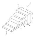
- FIG. 4 is a sectional view for describing dimensions of a superconducting coil used in a test.
- FIG. 5 is a graph showing a result obtained when the superconducting coil was energized in liquid helium.
- FIG. 6 is a graph showing a result obtained when the superconducting coil was energized in liquid helium.
- FIG. 7 is a diagram showing positions where a magnetic field was measured.
- FIG. 8 is a diagram showing magnetic field distribution in a case where a plurality of superconducting coils are arranged.
- FIG. 9 is a block diagram showing a superconducting magnet device of an embodiment of the present invention.
- ReBCO wire ReBCO superconducting wire
- FIG. 1 is a perspective view showing the structure of typical Y-based wire (Y-based superconducting wire).
- the Y-based wire 1 is tape-like oxide-based superconducting wire having a structure such that: a buffer layer 3 , a superconducting layer 4 , and a stabilizing layer 5 are formed on a substrate 2 in this order; and these are covered, in whole, with electrical insulation 6 .
- a buffer layer 3 a buffer layer 3 , a superconducting layer 4 , and a stabilizing layer 5 are formed on a substrate 2 in this order; and these are covered, in whole, with electrical insulation 6 .
- the stabilizing layer encloses the other layers including the substrate.
- the substrate 2 is made of Hastelloy, Ni-Alloy, or the like, and the buffer layer 3 is made of YSZ, MgO, CeO 2 , or the like. Further, the superconducting layer 4 is made of ReBCO, YBCO, NdBCO, SmBCO, or the like, and the stabilizing layer 5 is made of Ag, Ag—Cu, Cu, or the like.
- electrical insulation 6 for example, electrical insulating tape (polyimide or polyester) is used.
- the thickness of the substrate 2 is less than or equal to 200 ⁇ m, and the thicknesses of the buffer layer 3 , the superconducting layer 4 , and the stabilizing layer 5 are less than 3 ⁇ m, 1 to 10 ⁇ m, and 50 to 100 ⁇ m, respectively.
- the width of the Y-based wire 1 is on the order of 2 mm to 15 mm.
- FIGS. 2 and 3 are a diagram and a graph respectively, each showing a quench occurring in ReBCO superconducting wire and a quench occurring in metal-based superconducting wire.
- the normal-state zone When, in a superconducting coil made by winding superconducting wire, which is energized in the superconducting state, a part of the wire loses the superconducting state into the normal state, that is, it quenches, the normal-state zone is subjected to Joule heating caused by electric current flowing through the wire and electrical resistance generated thereby, which raises its temperature. This further increases the resistance, resulting in a further increase in temperature. The temperature increases sharply, and the normal-state zone may possibly be melted.
- the voltage across the superconducting coil or at apart thereof is measured, and a rapid change in voltage induced by increase or decrease in the magnitude of the magnetic field is detected, based on which its power supply is shut off.
- the ReBCO wire has a very thin superconducting layer, and therefore, after a change from the superconducting state to the normal state, resistance in the normal-state zone is smaller. That is, the voltage generated therein is so small that the change to the normal state is not timely detected with the above-described method using the change in voltage. As a result, the temperature in the normal-state zone increases extraordinarily, which may deteriorate superconducting characteristics of the ReBCO wire, or possibly, may result in burnout.
- Example 1 Two types of solenoid superconducting coils 11 and 12 (layer-wound coil) shown in FIG. 4 and Table 1 were fabricated using the ReBCO wire, to evaluate the effectiveness in detection of a quench. In Example 1, the superconducting coil 11 was used.
- the ReBCO wire used in a test was SCS4050 (Kapton (Registered Trademark), insulated) made by SuperPower Inc.
- the tape-like superconducting wire was wound around a barrel portion 7 b of a coil former 7 , which has flange portions 7 a and the barrel portion 7 b , to obtain the superconducting coil 11 , and the coil was impregnated with wax.
- a direction perpendicular to a tape surface of the ReBCO wire forming the superconducting coil 11 matches a radial direction of the superconducting coil 11 . Note that, in its windings, there were four joints between the superconducting wires, and the length of each joint is 100 mm.
- the superconducting coil 11 was energized in liquid helium in the absence of a magnetic field. Electric current flowing through the superconducting coil 11 was changed according to the following pattern: 0 A-40 A-200 A-300 A-310 A-320 A-330 A-340 A-350 A-360 A-367 A. As a result, the superconducting coil 11 burned out when the electric current was 367 A. A power supply for energizing the coil had been set so that the output electric current is promptly decreased to 0 A when the voltage between both ends of the superconducting coil 11 exceeds 0.1 V (100 mV).
- a superconducting coil made of metal-based superconducting wire does not burn out and no deterioration is found in its superconducting characteristics, even if the coil is energized according to the above-described pattern.
- the current density in the windings of the superconducting coil 11 at the operating current of 367 A was 257 A/mm 2 .
- FIG. 5 shows a result obtained when the superconducting coil 11 was energized.
- the screening field on an ordinate is the screening field at the center of the superconducting coil 11 (“coil center”).
- the screening field at the coil center is obtained by subtracting a magnetic field Bcal, which is a magnetic field in an axial direction of the coil calculated disregarding the effect of screening current, from a magnetic field in the axial direction measured at the coil center (“measured magnetic field B”).
- the value of the screening field greatly shifts in a negative direction.
- the voltage between both ends of the superconducting coil 11 gradually increased to about 0.5 mV, and then the voltage suddenly spiked and the superconducting coil 11 burned out.
- the voltage increase immediately before the voltage spike is on the same order of the voltage increase during the energization, and this shows that it is difficult to timely shut off the power supply based on the change in voltage between both ends of the coil.
- the change in screening field is slower than the change in voltage between both ends of the coil, which shows that the burnout of the superconducting coil 11 is prevented by shutting off the power supply when the value of the screening field reaches a predetermined threshold on the way to approaching 0 (zero). That is, the magnitude of the screening field is measured, and based on the thus obtained magnitude of the screening field, electric current flowing through the superconducting coil 11 (superconducting wire) is decreased (for example, the electric current is shut off (is promptly decreased to 0 (zero))), and thereby, damage to the superconducting coil 11 caused by a quench or the like is prevented.
- a recommended point for shutting off the power supply is shown as an example.
- Example 2 the above-described superconducting coil 12 was used.
- the ReBCO wire used in a test was SCS4050 (Kapton, non-insulated) made by Superpower Inc.
- the superconducting coil 12 was made through the following process: the wire of SCS4050 (Kapton, non-insulated) made by SuperPower Inc was coated with enamel (thickness: approximately 0.18 mm) to increase the current density in its windings; the coated wire was wound into a coil; and the thus obtained coil was impregnated with wax.
- the current density in the windings of the superconducting coil 12 is 1193 A/mm 2 for 0 T, and 795 A/mm 2 for 12 T, which are extremely high.
- FIG. 6 shows its result.
- FIG. 7 shows positions where the magnetic field was measured.
- the magnetic field was measured not only at the coil center P 1 , but also at a position near an outer periphery of an axial end of the coil (“coil peripheral position P 2 ”).
- a measured magnetic field B is the sum of a screening field Bs induced by screening current and a magnetic field Bcal calculated disregarding the effect of the screening current.
- the screening field Bs at the coil center P 1 (indicated with dotted lines), which is on the ordinate, was obtained by subtracting the magnetic field Bcal in the axial direction of the coil at the coil center P 1 , which magnetic field was calculated disregarding the effect of the screening current, from the measured magnetic field B in the axial direction of the coil at the coil center P 1 .
- the screening field Bs at the coil peripheral position P 2 was obtained by subtracting the magnetic field Bcal in a radial direction of the coil (the direction of the thickness of the ReBCO wire (superconducting wire) forming the superconducting coil 12 ) at the coil peripheral position P 2 , which magnetic field was calculated disregarding the effect of the screening current, from the measured magnetic field B in the radial direction of the coil at the coil peripheral position P 2 .
- the screening field Bs at the coil peripheral position P 2 became substantially 0 (zero) immediately before the quench.
- the voltage between both ends of the superconducting coil 12 sharply rises immediately before the quench, whereas the screening field Bs at the coil peripheral position P 2 gradually approaches 0 (zero).
- the screening field Bs is useful to shut off the power supply before the occurrence of the quench.
- FIG. 6 shows that, measurement of the magnetic field in the radial direction of the coil (the direction of the thickness of the superconducting wire) is remarkably effective to predict the occurrence of the quench in the superconducting coil.
- the outer peripheral surface of the coil is an area which is not used usually, and therefore, there is no problem in practice even if a magnetic sensor (a sensor for measuring a magnetic field, such as a Hall element, a pickup coil) is provided here.
- a magnetic sensor a sensor for measuring a magnetic field, such as a Hall element, a pickup coil
- FIG. 8 is a diagram showing magnetic field distribution in a case where a plurality of superconducting coils 21 and 22 are arranged. Each of a large number of arrows in the figure indicates the magnitude and direction of the magnetic field at the corresponding position.
- the radial direction of each superconducting coil made by winding the tape-like superconducting wire matches the direction of the thickness of the superconducting wire (specifically, the direction perpendicular to the tape surface).
- the magnetic field component in the direction of the thickness of the superconducting wire forming the superconducting coil (specifically, the direction perpendicular to the tape surface) at a position where the magnetic field component in the direction of the thickness of the superconducting wire forming the superconducting coil is larger.
- the magnetic field component in the direction of the thickness of the superconducting wire is largest at a position P 3 , followed by positions P 4 , P 5 , and P 6 in this order.
- the magnetic field component in the direction of the thickness of the superconducting wire forming the superconducting coil (specifically, the direction perpendicular to the tape surface) is larger at a position near the outer periphery of an axial end of the coil (an end in the axial direction of the coil).
- FIG. 9 is a block diagram showing a superconducting magnet device 100 of an embodiment of the present invention.
- the superconducting magnet device 100 includes: a superconducting coil 31 made by winding tape-like superconducting wire having a superconducting layer; a housing 32 for accommodating the superconducting coil 31 in the superconducting state; a power supply 33 for energizing the superconducting coil 31 ; and a protection circuit 40 for protecting the superconducting coil 31 from a quench.
- the superconducting wire forming the superconducting coil 31 is, for example, ReBCO wire typified by Y-based wire.
- the housing 32 is a vacuum vessel or a cryogenic vessel.
- the protection circuit 40 includes a protection resistor and the like. Electric current fed from the power supply 33 flows to the superconducting coil 31 via a current lead 41 .
- the superconducting magnet device 100 further includes a controller 34 which shuts off the power from the power supply 33 , based on the magnitude of a screening field induced by screening current flowing through the superconducting coil 31 (superconducting wire) which is in the superconducting state.
- the controller 34 includes: a magnetic sensor 35 which measures a magnetic field B in the direction of the thickness of the superconducting wire at a predetermined position; and a power shut-off device which shuts off the power fed from the power supply 33 to the superconducting coil 31 based on a signal from the magnetic sensor 35 .
- the power shut-off device includes: a reference voltage generator 37 ; a voltage comparator 36 ; and a power shut-off unit 38 , and the power shut-off device shuts off the power fed from the power supply 33 to the superconducting coil 31 based on the magnitude of a screening field Bs, which is a difference between the magnetic field B measured by the magnetic sensor 35 and a magnetic field Bcal in the direction of the thickness of the superconducting wire calculated disregarding the effect of the screening current.
- the magnetic sensor 35 is driven by a magnetic sensor driving device 39 .
- the magnetic sensor 35 is located in the vicinity of an outer peripheral surface of an upper axial end of the superconducting coil 31 . Note that, the position where the magnetic sensor 35 is provided is not limited to this. Further, the structure of the controller 34 is not limited to that in this embodiment.
- the reference voltage generator 37 outputs, to the voltage comparator 36 , a value of the screening field Bs (a value of that in the vicinity of the outer peripheral surface of the upper axial end of the superconducting coil 31 ) of a predetermined level at which the power from the power supply 33 should be shut off (a predetermined threshold value of the screening field Bs), as a reference voltage signal.
- the reference voltage signal from the voltage comparator 36 and a signal (signal of the measured magnetic field) from the magnetic sensor 35 are input to the voltage comparator 36 .
- the reference voltage signal (reference voltage) has been determined in advance based on a quench test or the like of the superconducting coil 31 ; however, it is changeable based on the status of operation.
- the voltage comparator 36 based on the signal from the magnetic sensor 35 (signal of the measured magnetic field), calculated is the magnitude of the screening field Bs, which is a difference between the magnetic field B measured by the magnetic sensor 35 and the magnetic field Bcal in the direction of the thickness of the superconducting wire calculated disregarding the effect of the screening current. Then, the voltage comparator 36 compares the thus obtained screening field Bs (voltage signal) with the reference voltage signal from the voltage comparator 36 . When the screening field Bs (voltage signal) increases once and then decreases, and thereafter it reaches (decreases to) the reference voltage (the predetermined threshold value), the voltage comparator 36 outputs, to the power shut-off unit 38 , an electric signal for shutting off the power from the power supply 33 . An electrical contact is opened by the power shut-off unit 38 , and thereby the power from the power supply 33 is shut off.
- the power from the power supply 33 is shut off by the power shut-off unit 38 based on the magnitude (an absolute value) of the screening field Bs; however, the present invention is not limited to such a manner that the power from the power supply 33 is shut off by the power shut-off unit 38 .
- the power supply may cause the amount of the electric current to be 0 (zero) or may decrease the electric current, by its own function. What is essential is to decrease the electric current flowing through the superconducting wire based on the magnitude of the screening field Bs, and there are many variations on the manners for decreasing the electric current flowing therethrough.
- Shutting off the power from the power supply 33 is one example of decreasing the electric current flowing through the superconducting wire.
- the magnetic field in the radial direction of the coil is measured in the vicinity of the outer peripheral surface of the upper axial end of the superconducting coil 31 ; however, the present invention is not limited to this.
- Prevention of a quench is achieved by: measuring a magnetic field (magnetic field component) whose direction is within ⁇ 40 degrees, preferably within ⁇ 36.9 degrees of the direction perpendicular to the tape surface of the tape-like superconducting wire at a position in the vicinity of the periphery of the coil, the position having a large magnetic field (magnetic field component) in the direction perpendicular to the tape surface; and determining an upper limit of the electric current flowing therethrough based on the magnitude of the screening field.
- sensitivity degradation in the value of the measured magnetic field is limited to not more than 20%.
- the “direction of the thickness” of the superconducting wire represents not only a direction strictly perpendicular to the tape surface of the superconducting wire, but encompasses a direction slightly inclined relative to the direction strictly perpendicular to the tape surface of the superconducting wire.
- the upper limit value of the electric current to be passed therethrough is determined in advance based on a change in or the magnitude of the screening field Bs immediately before a quench; the upper limit value is input beforehand to the reference voltage generator 37 as a reference voltage signal (reference voltage); the reference voltage signal (reference voltage) and the electric current flowing through the superconducting coil are compared with each other in the voltage comparator 36 ; and when the voltage signal representing the electric current flowing through the superconducting coil reaches the reference voltage, the electrical contact is opened by the power shut-off unit 38 , to shut off the power from the power supply 33 (to decrease the amount of the electric current flowing therethrough).
- the solenoid superconducting coil is described as an example; however, the present invention is also applicable to a superconducting coil made by winding superconducting wire into a shape of a pancake, a saddle, or the like.
Abstract
Description
| TABLE 1 | ||||||
| COIL | WINDING INNER | WINDING OUTER | WINDING | WIRE | COIL | |
| (REFERENCE | NUMBER OF TURNS × | DIAMETER | DIAMETER | HEIGHT | LENGTH | CONSTANT |
| SIGN) | NUMBER OF LAYERS | d(mm) | D(mm) | H(mm) | (m) | (mT/A) |
| 11 | 29 × 38 | 53 | 78 | 126 | 230 | 9.8 |
| 12 | 29 × 14 | 20 | 24 | 81 | 15 | 4.9 |
Claims (6)
Applications Claiming Priority (3)
| Application Number | Priority Date | Filing Date | Title |
|---|---|---|---|
| JP2011195756A JP5877397B2 (en) | 2011-09-08 | 2011-09-08 | Superconducting coil protection method and superconducting magnet device |
| JP2011-195756 | 2011-09-08 | ||
| PCT/JP2012/072359 WO2013035669A1 (en) | 2011-09-08 | 2012-09-03 | Superconducting coil protection method and superconducting magnet device |
Related Parent Applications (1)
| Application Number | Title | Priority Date | Filing Date |
|---|---|---|---|
| PCT/JP2012/072359 Continuation WO2013035669A1 (en) | 2011-09-08 | 2012-09-03 | Superconducting coil protection method and superconducting magnet device |
Publications (2)
| Publication Number | Publication Date |
|---|---|
| US20140235451A1 US20140235451A1 (en) | 2014-08-21 |
| US9543754B2 true US9543754B2 (en) | 2017-01-10 |
Family
ID=47832114
Family Applications (1)
| Application Number | Title | Priority Date | Filing Date |
|---|---|---|---|
| US14/201,561 Expired - Fee Related US9543754B2 (en) | 2011-09-08 | 2014-03-07 | Superconducting coil protection method and superconducting magnet device |
Country Status (4)
| Country | Link |
|---|---|
| US (1) | US9543754B2 (en) |
| EP (1) | EP2755216B1 (en) |
| JP (1) | JP5877397B2 (en) |
| WO (1) | WO2013035669A1 (en) |
Families Citing this family (7)
| Publication number | Priority date | Publication date | Assignee | Title |
|---|---|---|---|---|
| GB201515979D0 (en) | 2015-09-09 | 2015-10-21 | Tokamak Energy Ltd | Quench protection in superconducting magnets |
| US10401393B2 (en) * | 2016-06-28 | 2019-09-03 | The United States Of America As Represented By The Secretary Of The Army | Method for determining persistent critical current of superconducting materials |
| KR101768211B1 (en) * | 2016-11-01 | 2017-08-17 | 한국기초과학지원연구원 | Simulation apparatus for predicting temperature at phase change of super conducting coil and the method thereof |
| GB201702134D0 (en) | 2017-02-09 | 2017-03-29 | Tokamak Energy Ltd | Cryogenic magnet power supply |
| GB201801604D0 (en) * | 2018-01-31 | 2018-03-14 | Tokamak Energy Ltd | magnetic quench induction system |
| GB2588901A (en) * | 2019-11-12 | 2021-05-19 | Tokamak Energy Ltd | Strain-based quench detection |
| WO2023234915A1 (en) * | 2022-05-28 | 2023-12-07 | University Of Houston System | Quench detection in superconductors |
Citations (13)
| Publication number | Priority date | Publication date | Assignee | Title |
|---|---|---|---|---|
| JPS5474391A (en) | 1977-11-25 | 1979-06-14 | Toshiba Corp | Supervisory equipment for superconductive magnet |
| JPS57141904A (en) | 1981-02-27 | 1982-09-02 | Hitachi Ltd | Power source controlling device of super conduction device |
| US4349853A (en) * | 1979-02-13 | 1982-09-14 | Tokyo Shibaura Denki Kabushiki Kaisha | Strong magnetic field generator and method of operating the same |
| EP0423927A2 (en) | 1989-08-31 | 1991-04-24 | Westinghouse Electric Corporation | Monitoring system for detecting quench |
| WO1995004449A1 (en) | 1993-08-03 | 1995-02-09 | Midwest Superconductivity, Inc. | HIGH Tc SUPERCONDUCTOR MAGNETIC SHIELDS AND METHOD OF MAKING SAME |
| US5929385A (en) | 1996-05-10 | 1999-07-27 | The Furukawa Electric Co., Ltd | AC oxide superconductor wire and cable |
| JP2001274014A (en) | 2000-03-24 | 2001-10-05 | Toshiba Corp | Superconductive coil device |
| WO2006115126A1 (en) | 2005-04-19 | 2006-11-02 | Kabushiki Kaisha Toshiba | Superconducting coil quench detection method and device, and superconducting power storage unit |
| JP2006319139A (en) | 2005-05-12 | 2006-11-24 | Sumitomo Electric Ind Ltd | Superconducting apparatus and quenching protecting method of superconducting portion |
| US20070053116A1 (en) * | 2005-09-05 | 2007-03-08 | Michiharu Ichikawa | Quench detection method and apparatus of superconductive conductor |
| JP2007215635A (en) | 2006-02-15 | 2007-08-30 | Hitachi Medical Corp | Magnetic resonance imaging apparatus |
| US20090122508A1 (en) * | 2007-10-31 | 2009-05-14 | Uchaykin Sergey V | Systems, methods, and apparatus for combined superconducting magnetic shielding and radiation shielding |
| JP2009246162A (en) | 2008-03-31 | 2009-10-22 | Toshiba Corp | Superconducting coil device, method of detecting abnormal condition of superconducting coil and method of operating superconducting coil device |
-
2011
- 2011-09-08 JP JP2011195756A patent/JP5877397B2/en not_active Expired - Fee Related
-
2012
- 2012-09-03 WO PCT/JP2012/072359 patent/WO2013035669A1/en active Application Filing
- 2012-09-03 EP EP12830432.6A patent/EP2755216B1/en not_active Not-in-force
-
2014
- 2014-03-07 US US14/201,561 patent/US9543754B2/en not_active Expired - Fee Related
Patent Citations (15)
| Publication number | Priority date | Publication date | Assignee | Title |
|---|---|---|---|---|
| JPS5474391A (en) | 1977-11-25 | 1979-06-14 | Toshiba Corp | Supervisory equipment for superconductive magnet |
| US4349853A (en) * | 1979-02-13 | 1982-09-14 | Tokyo Shibaura Denki Kabushiki Kaisha | Strong magnetic field generator and method of operating the same |
| JPS57141904A (en) | 1981-02-27 | 1982-09-02 | Hitachi Ltd | Power source controlling device of super conduction device |
| EP0423927A2 (en) | 1989-08-31 | 1991-04-24 | Westinghouse Electric Corporation | Monitoring system for detecting quench |
| JPH03105275A (en) | 1989-08-31 | 1991-05-02 | Westinghouse Electric Corp <We> | Sensor for detecting quench of superconductor |
| WO1995004449A1 (en) | 1993-08-03 | 1995-02-09 | Midwest Superconductivity, Inc. | HIGH Tc SUPERCONDUCTOR MAGNETIC SHIELDS AND METHOD OF MAKING SAME |
| US5929385A (en) | 1996-05-10 | 1999-07-27 | The Furukawa Electric Co., Ltd | AC oxide superconductor wire and cable |
| JP2001274014A (en) | 2000-03-24 | 2001-10-05 | Toshiba Corp | Superconductive coil device |
| WO2006115126A1 (en) | 2005-04-19 | 2006-11-02 | Kabushiki Kaisha Toshiba | Superconducting coil quench detection method and device, and superconducting power storage unit |
| US20090046399A1 (en) | 2005-04-19 | 2009-02-19 | Kabushiki Kaisha Toshiba | Superconducting coil quench detection method and device, and superconducting power storage unit |
| JP2006319139A (en) | 2005-05-12 | 2006-11-24 | Sumitomo Electric Ind Ltd | Superconducting apparatus and quenching protecting method of superconducting portion |
| US20070053116A1 (en) * | 2005-09-05 | 2007-03-08 | Michiharu Ichikawa | Quench detection method and apparatus of superconductive conductor |
| JP2007215635A (en) | 2006-02-15 | 2007-08-30 | Hitachi Medical Corp | Magnetic resonance imaging apparatus |
| US20090122508A1 (en) * | 2007-10-31 | 2009-05-14 | Uchaykin Sergey V | Systems, methods, and apparatus for combined superconducting magnetic shielding and radiation shielding |
| JP2009246162A (en) | 2008-03-31 | 2009-10-22 | Toshiba Corp | Superconducting coil device, method of detecting abnormal condition of superconducting coil and method of operating superconducting coil device |
Non-Patent Citations (7)
| Title |
|---|
| International Preliminary Report on Patentability issued Mar. 20, 2014 in PCT/JP2012/072359 filed Sep. 3, 2012. |
| International Search Report issued Nov. 27, 2012 in PCT Application No. PCT/JP2012/072359, with English Translation. |
| Japanese Office Action issued Sep. 8, 2015 in Patent Application No. 2011-195756 (with English Translation). |
| Masao Shimada, V-1. "Metal Superconductive Wires", Cryogenics, 1994, vol. 29 No. 9, pp. 453-461 (with Partial English Translation). |
| Noriyuki Shimizu et al., "Distributors of Current and Magnetic Field in AC Superconducting Cable and Detection of Quench", Articles of the Institute of Electrical Engineers of Japan, B, 1967, vol. 107, No. 9, pp. 457-463. |
| Written Opinion issued Nov. 27, 2012 in PCT/JP2012/072359 filed Sep. 3, 2012 (with English translation). |
| Y. Yanagisawa, et al., "Effect of Current Sweep Reversal on the Magnetic Field Stability for a Bi-2223 Superconducting Solenoid" Elsevier-Physica C, vol. 469, No. 22, 2009, pp. 1996-1999. |
Also Published As
| Publication number | Publication date |
|---|---|
| EP2755216A1 (en) | 2014-07-16 |
| EP2755216B1 (en) | 2017-01-04 |
| JP5877397B2 (en) | 2016-03-08 |
| WO2013035669A1 (en) | 2013-03-14 |
| EP2755216A4 (en) | 2015-05-06 |
| US20140235451A1 (en) | 2014-08-21 |
| JP2013058588A (en) | 2013-03-28 |
Similar Documents
| Publication | Publication Date | Title |
|---|---|---|
| US9543754B2 (en) | Superconducting coil protection method and superconducting magnet device | |
| Wang et al. | High temperature superconducting YBCO insert for 25 T full superconducting magnet | |
| JP2006313924A (en) | High temperature superconducting coil, and high temperature superconducting magnet and high temperature superconducting magnet system employing it | |
| JP2000277322A (en) | High-temperature superconducting coil, high-temperature superconducting magnet using the same, and high- temperature superconducting magnet system | |
| WO2017061563A1 (en) | Superconducting coil | |
| JP5656734B2 (en) | Superconducting magnet having parallel winding and superconducting magnet system | |
| JP2005191539A (en) | Superconducting current limiting device | |
| Miyazaki et al. | Over-current test of REBCO pancake coils impregnated with electrically conductive epoxy resin under conduction-cooled conditions | |
| JP4719090B2 (en) | High temperature superconducting coil and high temperature superconducting magnet using the same | |
| Fleiter et al. | Characterization of Nb 3 Sn Rutherford cable degradation due to strands cross-over | |
| JP2012248725A (en) | Superconducting magnet device, and quenching detector and detection method of superconducting coil | |
| JP5175640B2 (en) | Superconducting coil | |
| Tsuchiya et al. | Prototype HTS sextupole magnet for superKEKB interaction region | |
| JP6220554B2 (en) | Quench detection device and quench detection method for superconducting coil | |
| Sasaki et al. | Study on quench protection of coil wound of Bi/Ag-sheathed wire | |
| Matsuo et al. | Study on hot-spot temperature limits of epoxy-impregnated coil wound with Bi/Ag sheathed wire to be safe from damage caused by quenches | |
| GB2126028A (en) | Quench detector for superconducting winding | |
| US20110152102A1 (en) | Device and method of measuring electrical dissipation in a superconducting coil | |
| Polyakov et al. | Small layer-wound ReBCO solenoids | |
| Majoros et al. | Quench Measurements in a YBCO Pancake Coil at 77 K and 4.2 K in Magnetic Fields up to 10 Tesla | |
| NL2029557B1 (en) | An electromagnet coil assembly. | |
| JP2018026222A (en) | Tape type high temperature superconducting wire | |
| JP2019029285A (en) | Superconductor for non-insulated superconducting coil and superconducting coil therewith | |
| Kawagoe et al. | A measurement method of AC losses in superconducting coils using Poynting's vector method | |
| Li et al. | Analysis of damage by quench and improvements in rewinding for a 9.4-T superconducting NMR magnet |
Legal Events
| Date | Code | Title | Description |
|---|---|---|---|
| AS | Assignment |
Owner name: JAPAN SUPERCONDUCTOR TECHNOLOGY, INC. (20%), JAPAN Free format text: ASSIGNMENT OF ASSIGNORS INTEREST;ASSIGNORS:KIYOSHI, TSUKASA AS REPRESENTED BY HEIR, KIYOSHI, CHIEKO;KIYOSHI, TSUKASA AS REPRESENTED BY HEIR, KIYOSHI, MASATAKA;REEL/FRAME:032391/0704 Effective date: 20131209 Owner name: NATIONAL INSTITUTE FOR MATERIALS SCIENCE (80%), JA Free format text: ASSIGNMENT OF ASSIGNORS INTEREST;ASSIGNORS:KIYOSHI, TSUKASA AS REPRESENTED BY HEIR, KIYOSHI, CHIEKO;KIYOSHI, TSUKASA AS REPRESENTED BY HEIR, KIYOSHI, MASATAKA;REEL/FRAME:032391/0704 Effective date: 20131209 Owner name: NATIONAL INSTITUTE FOR MATERIALS SCIENCE (80%), JA Free format text: ASSIGNMENT OF ASSIGNORS INTEREST;ASSIGNORS:UGLIETTI, DAVIDE;MATSUMOTO, SHINJI;HAMADA, MAMORU;SIGNING DATES FROM 20131119 TO 20131127;REEL/FRAME:032389/0471 Owner name: JAPAN SUPERCONDUCTOR TECHNOLOGY, INC. (20%), JAPAN Free format text: ASSIGNMENT OF ASSIGNORS INTEREST;ASSIGNORS:UGLIETTI, DAVIDE;MATSUMOTO, SHINJI;HAMADA, MAMORU;SIGNING DATES FROM 20131119 TO 20131127;REEL/FRAME:032389/0471 |
|
| FEPP | Fee payment procedure |
Free format text: PAYOR NUMBER ASSIGNED (ORIGINAL EVENT CODE: ASPN); ENTITY STATUS OF PATENT OWNER: LARGE ENTITY |
|
| STCF | Information on status: patent grant |
Free format text: PATENTED CASE |
|
| FEPP | Fee payment procedure |
Free format text: MAINTENANCE FEE REMINDER MAILED (ORIGINAL EVENT CODE: REM.); ENTITY STATUS OF PATENT OWNER: LARGE ENTITY |
|
| LAPS | Lapse for failure to pay maintenance fees |
Free format text: PATENT EXPIRED FOR FAILURE TO PAY MAINTENANCE FEES (ORIGINAL EVENT CODE: EXP.); ENTITY STATUS OF PATENT OWNER: LARGE ENTITY |
|
| STCH | Information on status: patent discontinuation |
Free format text: PATENT EXPIRED DUE TO NONPAYMENT OF MAINTENANCE FEES UNDER 37 CFR 1.362 |
|
| FP | Lapsed due to failure to pay maintenance fee |
Effective date: 20210110 |