JP2010006482A - Balance weight device for elevator - Google Patents
Balance weight device for elevator Download PDFInfo
- Publication number
- JP2010006482A JP2010006482A JP2008164437A JP2008164437A JP2010006482A JP 2010006482 A JP2010006482 A JP 2010006482A JP 2008164437 A JP2008164437 A JP 2008164437A JP 2008164437 A JP2008164437 A JP 2008164437A JP 2010006482 A JP2010006482 A JP 2010006482A
- Authority
- JP
- Japan
- Prior art keywords
- counterweight
- balance weight
- frame
- storage space
- weight device
- Prior art date
- Legal status (The legal status is an assumption and is not a legal conclusion. Google has not performed a legal analysis and makes no representation as to the accuracy of the status listed.)
- Granted
Links
Images


Abstract
Description
本発明は、釣合重りの積み込み作業を容易に行うことが可能なエレベータ用の釣合重り装置に関する。 The present invention relates to a balance weight device for an elevator that can easily carry out a work of loading a balance weight.
従来より、内部に収納空間が形成された釣合重り枠体と、収納空間に多段に積み重ねられた板状の複数の釣合重りと、を備えたエレベータ用の釣合重り装置が知られている。このうち、多段に積み重ねられた板状の複数の釣合重りの上部に位置する釣合重りは、エレベータの乗りかごと、釣合重りとのバランスを調整するため、エレベータの昇降路内において、乗りかごの上に位置する人又は機械により釣合重り枠体に積み込まれる。 2. Description of the Related Art Conventionally, there has been known a balance weight device for an elevator including a balance weight frame body in which a storage space is formed and a plurality of plate-like balance weights stacked in multiple stages in the storage space. Yes. Among these, the balance weight located at the upper part of a plurality of plate-like counterweights stacked in multiple stages is in the elevator hoistway in order to adjust the balance between the elevator car and the balance weight. It is loaded onto the counterweight frame by a person or machine located on the car.
しかしながら、釣合重りは、乗りかごの上に位置する人又は機械により積み込まれるため、釣合重りの積み込み作業は危険かつ困難であった。さらに、乗りかごと釣合重り装置の間隔が広い場合は、この釣合重りの積み込み作業はより多くの危険と困難を伴う作業であった。 However, since the counterweight is loaded by a person or machine located on the car, the loading operation of the counterweight has been dangerous and difficult. Further, when the interval between the car and the balance weight device is wide, the work of loading the balance weight is a work with more danger and difficulty.
本発明は、このような点を考慮してなされたものであり、乗りかごから釣合重り装置への重りの積み込み作業を容易に行うことが可能なエレベータの釣合重り装置を提供することを目的とする。 The present invention has been made in consideration of the above points, and provides an elevator balancing weight device capable of easily loading a weight from a passenger car to a balancing weight device. Objective.
本発明は、エレベータ用の釣合重り装置において、内部に収納空間が形成された釣合重り枠体と、当該釣合重り枠体の収納空間に多段に積み重ねられた板状の複数の釣合重りと、を備え、前記釣合重り枠体の収納空間に多段に積み重ねられた板状の複数の釣合重りのうち、少なくとも最上段の釣合重りの一部に、作業用の大きさの穴を設けたことを特徴とするエレベータ用の釣合重り装置である。 The present invention relates to a balance weight device for an elevator, a balance weight frame having a storage space formed therein, and a plurality of plate-shaped balances stacked in multiple stages in the storage space of the balance weight frame. A plurality of plate-like counterweights stacked in multiple stages in the storage space of the counterweight frame body, and at least part of the uppermost counterweight has a working size. A counterweight device for an elevator, wherein a hole is provided.
本発明は、釣合重り枠体の収納空間に多段に積み重ねられた板状の複数の釣合重りのうち、少なくとも最上段の釣合重りは、2つの釣合重り片に分割され、一方の釣合重り片に凹溝が形成され、他方の釣合重り片に一方の釣合重り片の凹溝に嵌め込まれる凸部が形成され、作業用の穴は、一方の釣合重り片と、他方の釣合重り片の双方に設けられていることを特徴とする請求項1に記載のエレベータ用の釣合重り装置である。 In the present invention, among the plurality of plate-like counterweights stacked in multiple stages in the storage space of the counterweight frame, at least the uppermost counterweight is divided into two counterweight pieces, A concave groove is formed in the counterweight piece, and a convex portion is formed in the other counterweight piece to be fitted into the concave groove of one counterweight piece, and the working hole is formed with one counterweight piece, The balance weight device for an elevator according to claim 1, wherein the balance weight device is provided on both of the other balance weight pieces.
本発明は、エレベータ用の釣合重り装置において、内部に収納空間が形成された釣合重り枠体と、釣合重り枠体の収納空間上部に設けられ、所定方向に移動可能な収容部と、各引出し内に収納された板状の釣合重りと、を備えたことを特徴とするエレベータ用の釣合重り装置である。 The present invention relates to a balance weight device for an elevator, a balance weight frame body in which a storage space is formed, and a storage portion that is provided above the storage space of the balance weight frame body and is movable in a predetermined direction. A balance weight device for an elevator, comprising: a plate-shaped balance weight housed in each drawer.
本発明は、エレベータ用の釣合重り装置において、内部に収納空間が形成された釣合重り枠体と、当該釣合重り枠体の収納空間に多段に積み重ねられた板状の複数の釣合重りと、を備え、前記釣合重り枠体内の一側に垂直方向に伸びる棒又はワイヤを設け、各釣合重りの一側にこの棒又はワイヤが挿入されるとともに外方に開口する開口部を有する挿入口を形成し、挿入口の開口部にカラビナ式のフックを設け、このカラビナ式のフックを介して棒又はワイヤを挿入口内に挿入可能としたことを特徴とするエレベータ用の釣合重り装置である。 The present invention relates to a balance weight device for an elevator, a balance weight frame having a storage space formed therein, and a plurality of plate-shaped balances stacked in multiple stages in the storage space of the balance weight frame. And a bar or wire that extends vertically on one side of the balance weight frame, and the bar or wire is inserted on one side of each balance weight and opens outward. A balance for an elevator, characterized in that a carabiner-type hook is formed in the opening of the insertion opening, and a rod or a wire can be inserted into the insertion opening via the carabiner-type hook. It is a weight device.
本発明は、エレベータ用の釣合重り装置において、内部に収納空間が形成された釣合重り枠体と、当該釣合重り枠体の収納空間に多段に積み重ねられた板状の複数の釣合重りと、を備え、前記釣合重り枠体は、一対の側枠と、一対の側枠上部に設けられた上部枠と、一対の側枠底部に設けられた底部枠とを有し、上部枠に吊上げフックを設けるとともに、釣合重り枠体の収納空間に多段に積み重ねられた板状の複数の釣合重りのうち少なくとも最上段の釣合重りに係止部を設け、この釣合重りの係止部にロープの一端を係合させるとともに、このロープを吊上げフックに掛け渡したことを特徴とするエレベータ用の釣合重り装置である。 The present invention relates to a balance weight device for an elevator, a balance weight frame having a storage space formed therein, and a plurality of plate-shaped balances stacked in multiple stages in the storage space of the balance weight frame. The counterweight frame body includes a pair of side frames, an upper frame provided at the upper part of the pair of side frames, and a bottom frame provided at the bottom part of the pair of side frames, A lifting hook is provided on the frame, and a locking portion is provided on at least the uppermost counterweight among the plurality of plate-like counterweights stacked in the storage space of the counterweight frame. An elevator balancing weight device characterized in that one end of a rope is engaged with an engaging portion of the elevator and the rope is stretched over a lifting hook.
本発明によれば、釣合重り装置へ釣合重りを容易かつ安全に積み込むことができる。 According to the present invention, the counterweight can be easily and safely loaded into the counterweight device.
第1の実施の形態
以下、図面を参照して、本発明の第1の実施の形態について説明する。ここで、図1および図2は、本発明の第1の実施の形態におけるエレベータ用の釣合重り装置を示す図である。このうち図1は、本発明の第1の実施の形態におけるエレベータ用の釣合重り装置を示す図であり、図2は、本発明の第1の実施の形態における分割された釣合重り片からなる釣合重りを示す図である。
First Embodiment Hereinafter, a first embodiment of the present invention will be described with reference to the drawings. Here, FIG. 1 and FIG. 2 are views showing a balance weight device for an elevator according to the first embodiment of the present invention. Of these, FIG. 1 is a view showing a balance weight device for an elevator according to the first embodiment of the present invention, and FIG. 2 is a diagram of divided weight pieces according to the first embodiment of the present invention. It is a figure which shows the counterweight which consists of.
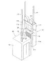
まず、図1によりエレベータ装置40全体について説明する。図に示すように、エレベータ装置40はエレベータの乗りかご19と、エレベータの乗りかご19にメインロープ17を介して連結された釣合重り装置10とを備えている。このうち乗りかご19と釣合重り装置10とを連結するメインロープ17は、図示しない巻上機により駆動されるようになっている。
First, the
次に本発明による釣合重り装置10について説明する。図1に示すように釣合重り装置10は、内部に収納空間11sが形成された釣合重り枠体11と、釣合重り枠体11の収納空間11sに多段に積み重ねられた板状の複数の釣合重り14とを備えている。このうち、釣合重り枠体11は、対向して配置されたコ字状形状を有する一対の側枠11a、11aと、側枠11a、11aの上端に連結された上部枠11bと、側枠11a、11aの下端に連結された底部枠11cとを有している。また各釣合重り14には、その一部に手のひらを通すことができる程度の大きさの、作業用の長穴15が設けられている。なお、各釣合重り14は釣合重り枠体11の一対の側枠11a、11a間全長に渡って延び、その重さは10kg程度となっている。
Next, the
また、釣合重り装置10は、上部枠11bの上部に設けられた釣合重り装置用滑車16を有し、この釣合重り装置用滑車16にはメインロープ17が掛け渡されており、メインロープ17は上述のように乗りかご用滑車18を介して、乗りかご19に連結されている。なお乗りかご19の上には、後述のように釣合重り枠体11内の釣合重り14の数量を調整するため、作業者20が乗っている。
Further, the
次に、このような構成からなる本実施の形態の作用について説明する。 Next, the operation of the present embodiment having such a configuration will be described.
まず図1に示すように、釣合重り装置10と乗りかご19が近接するようにメインロープ17を巻上機により駆動させる。次に、乗りかご19上に釣合重り14が配置され、かつ作業者20が乗りかご19の上に乗り込み、作業者20が釣合重り14を釣合重り枠体11の内部の収納空間11sに積み込む。
次に作業者20が釣合重り14を積み込む作用について述べる。作業者20は片手を釣合重り14の一部に設けられた長穴15に挿入し、釣合重り14を持ち上げる。他方の手は、乗りかご19の一部又は釣合重り枠体11の一部を掴む。次に釣合重り14を斜めに倒し、その状態で釣合重り枠体11の内部の収納空間11sに釣合重り14を挿入し、積載済みの釣合重り14の上に新たに釣合重り14を積み重ねる。
First, as shown in FIG. 1, the
Next, the operation of the
このように本実施の形態によれば、作業者20が乗りかご19の上から釣合重り14を釣合重り装置10に積み込む場合、片手で釣合重り14を持ち上げて釣合重り枠体11の収納空間11s内に積み込むことができる。このような連結作業においては、作業者20は他方の手で乗りかご19の一部又は釣合重り枠体11の一部を掴むことができるので、乗りかご19と釣合重り装置10の間隔が広い場合においても、釣合重り14を釣合重り枠体11の収納空間11s内に容易かつ安全に積み込むことができる。
As described above, according to the present embodiment, when the
なお、図1において、各釣合重り14は釣合重り枠体11の一対の側枠11a、11a間全長に渡って延びているが、これに限らず、図2に示すように釣合重り枠体11の収納空間11sに積み重ねられた釣合重り14のうち、少なくとも最上段の釣合重り14を、2等分に分割された2つの釣合重り片である分割釣合重り30a、分割釣合重り30bから構成してもよい。この場合、一方の分割釣合重り30aには凹溝49aが形成され、他方の分割釣合重り30bには一方の分割釣合重り30aの凹溝49a内に嵌め込まれる凸部49bが形成されている。
In FIG. 1, each
上述のように、最上段の釣合重り14は、分割された2つの分割釣合重り30a、分割釣合重り30bを有し、分割釣合重り30aには凹溝49aが形成され、分割釣合重り30bには凸部49bが形成されている。また各分割釣合重り30a、分割釣合重り30bには、手のひらを通すことができる程度の大きさの、作業用の長穴15が形成されている。また釣合重り14の分割釣合重り30a、分割釣合重り30bは各々最上段以外の釣合重り14の2倍程度の厚さを有し、また釣合重り14の分割釣合重り30a、分割釣合重り30bは各々10kg程度の重さを有している。従って、分割釣合重り30a、分割釣合重り30bは各々最上段以外の釣合重り14と同様の重さを有することになる。
As described above, the
図2において、作業者20は片手を分割釣合重り30aの一部に設けられた長穴15に挿入し、分割釣合重り30aを持ち上げる。他方の手は、乗りかご19の一部又は釣合重り枠体11の一部を掴む。次に分割釣合重り30aを斜めに倒し、その状態で釣合重り枠体11の収納空間11s内に分割釣合重り30aを挿入し、積載済みの釣合重り14の上に新たに分割釣合重り30aを積み重ねる。その分割釣合重り30aの横に、分割釣合重り30bを積み込み、分割釣合重り30aの凹溝49aに分割釣合重り30bの凸部49bを嵌め込み、分割釣合重り30aと分割釣合重り30bを連結する。
In FIG. 2, the
このように本実施の形態によれば、作業者20が乗りかご19の上から釣合重り14を釣合重り装置10に積み込む場合、片手で分割釣合重り30a又は分割釣合重り30bを持ち上げて釣合重り枠体11の収納空間11s内に積み込むことができる。このような連結作業においては、作業者20は他方の手で乗りかご19の一部又は釣合重り枠体11の一部を掴むことができるので、乗りかご19と釣合重り装置10の間隔が広い場合においても、釣合重り14を釣合重り枠体11の収納空間11s内に容易かつ安全に積み込むことができる。
As described above, according to the present embodiment, when the
また、本実施の形態においては、図2に示すように、釣合重り枠体11の一対の側枠11a、11a間全長に渡って延びている釣合重り14の代わりに、2等分に分割された2つの釣合重り片である分割釣合重り30a、分割釣合重り30bから構成される釣合重り14を積み込むことができる。従って、分割釣合重り30a、分割釣合重り30bの長さは釣合重り枠体11の一対の側枠11a、11a間の半分の長さとなるので、分割釣合重り30a、分割釣合重り30bを釣合重り枠体11の収納空間11s内へより容易に積み込むことができる。
Further, in the present embodiment, as shown in FIG. 2, instead of the
また、本実施の形態において、図2に示すように、釣合重り14を、2等分に分割された2つの釣合重り片である分割釣合重り30a、分割釣合重り30bから構成する例を示したが、これに限られず、釣合重り14を3つ又はそれ以上の数に分割してもよい。この場合、釣合重り14を3つ又はそれ以上の数に分割することにより、各分割釣合重りの長さをより短くすることができ、この分割釣合重りを釣合重り枠体11の収納空間11s内に容易かつ安全に積み込むことができる。
Moreover, in this Embodiment, as shown in FIG. 2, the
第2の実施の形態
以下、図3および図4を参照して、本発明の第2の実施の形態について説明する。ここで、図3は、本発明の第2の実施の形態におけるエレベータ用の釣合重り装置を示す図であり、図4は、本発明の第2の実施の形態における釣合重り装置を示す図である。
Second Embodiment Hereinafter, a second embodiment of the present invention will be described with reference to FIGS. 3 and 4. FIG. Here, FIG. 3 is a diagram showing a balance weight device for an elevator according to the second embodiment of the present invention, and FIG. 4 shows a balance weight device according to the second embodiment of the present invention. FIG.
図3および図4に示す第2の実施の形態において、釣合重り枠体11に引出し31が設けられている点が異なるのみであり、他の構成は、図1および図2に示す第1の実施の形態と略同一である。図3および図4において、図1および図2に示す第1の実施の形態と同一部分には同一符号を付して詳細な説明は省略する。
3 and FIG. 4 is different from the second embodiment shown in FIG. 3 and FIG. 4 only in that the
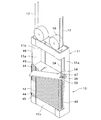
図3および図4に示すように釣合重り装置10は、内部に収納空間11sが形成された釣合重り枠体11と、釣合重り枠体11の収納空間11sに多段に積み重ねられた板状の複数の釣合重り14と、釣合重り枠体11の収納空間11s上部に多段に、例えば5段に設けられた、所定方向に移動可能な収容部、例えば引出し31とを備えている。また5段の引出し31内には各々板状の釣合重り41を収納することができる。なお図3および図4に示すように一対の側枠11a、11aの前面には切欠部42が各々設けられ、引出し31は切欠部42に嵌め込まれている。各切欠部42の高さは、引出し31の高さとほぼ同一である。また引出し31の右側面後部および左側面後部には突起部32、32が設けられ、引出し31の前面の両端にはストッパ33、33が設けられ、引出し31の前面の中央には取っ手43が設けられている。この場合、引出し31の後面が一対の側枠11a、11aの後面に当接することにより引出し31が釣合重り枠体11内で位置決めされる。またストッパ33、33を側枠11a、11aに係止することにより、引出し31は釣合重り枠体11内で堅固に固定される。
As shown in FIGS. 3 and 4, the
次に、このような構成からなる本実施の形態の作用について説明する。 Next, the operation of the present embodiment having such a configuration will be described.
まず図3に示すように、釣合重り装置10と乗りかご19が近接するようにメインロープ17を巻上機により駆動させる。次に、乗りかご19上に釣合重り41が配置され、かつ作業者20が乗りかご19の上に乗り込み、作業者20が釣合重り41を釣合重り枠体11の収納空間11s内に積み込む。
次に作業者20が釣合重り枠体11の収納空間11s内に釣合重り41を積み込む作用について述べる。まず釣合重り枠体11の収納空間11s内の下方部および中央部には予め板状の釣合重り14が積み込まれている。次に作業者20は引出し31の前面の両端に設けられたストッパ33、33を外し、引出し31の前面の中央に設けられた取っ手43を掴み、引出し31を乗りかご19に向けて引き出す。その際、引出し31の右側面後部および左側面後部に設けられた突起部32、32が一対の側枠11a、11aの前面に設けられた切欠部42、42と接触するまで、作業者20は引出し31を乗りかご19に向けて引き出すことができる。次に、作業者20は釣合重り41を持ち上げ、釣合重り41を引出し31内に収納する。次に、作業者20は引出し31を釣合重り枠体11に向けて押し戻す。次に、作業者20は引出し31の前面の両端にストッパ33、33を嵌め込み、引出し31を釣合重り枠体11に堅固に固定する。
First, as shown in FIG. 3, the
Next, an operation in which the
このように本実施の形態によれば、作業者20が釣合重り41を持った状態で乗りかご19から釣合重り装置10の方向に向かって体を乗り出すことなく、乗りかご19の上で作業者20が釣合重り枠体11から引出し31を引き出し、次に釣合重り41を引出し31内に収納して引出し31を釣合重り枠体11側へ押し戻すだけで、釣合重り41を釣合重り枠体11の収納空間11s内に容易に積み込むことができる。これにより、乗りかご19と釣合重り装置10の間隔が広い場合においても、釣合重り41を釣合重り枠体11の収納空間11s内に容易かつ安全に積み込むことができる。
As described above, according to the present embodiment, the
第3の実施の形態
以下、図5および図6を参照して、本発明の第3の実施の形態について説明する。ここで、図5は、本発明の第3の実施の形態におけるエレベータ用の釣合重り装置を示す図であり、図6は、本発明の第3の実施の形態における釣合重り装置を示す図である。
Third Embodiment Hereinafter, a third embodiment of the present invention will be described with reference to FIGS. 5 and 6. FIG. Here, FIG. 5 is a view showing a balance weight device for an elevator according to the third embodiment of the present invention, and FIG. 6 shows a balance weight device according to the third embodiment of the present invention. FIG.
図5および図6に示す第3の実施の形態において、釣合重り枠体11の一側に垂直方向に伸びる棒34が設けられ、各釣合重り14の一側に棒34が挿入されるとともに外方に開口する開口部50を有する挿入口47が形成され、挿入口47の開口部50にカラビナ式のフック35が設けられている点が異なるのみであり、他の構成は、図1および図2に示す第1の実施の形態と略同一である。図5および図6において、図1および図2に示す第1の実施の形態と同一部分には同一符号を付して詳細な説明は省略する。
In the third embodiment shown in FIGS. 5 and 6, a
図5および図6に示すように釣合重り装置10は、内部に収納空間11sが形成された釣合重り枠体11と、釣合重り枠体11の収納空間11sに多段に積み重ねられた板状の複数の釣合重り14とを備えている。また図5および図6に示すように、釣合重り枠体11内の右側には垂直方向に延びる棒34が設けられ、右側の側枠11aには収納空間11sと同じ高さの切欠部46が側枠11aの前面および側面に設けられ、左側の側枠11aには収納空間11sと同じ高さの切欠部48が側枠11aの前面に設けられている。また、左側の側枠11aの側面には複数の止め板45が対応するストッパ44により連結されている。なお、各止め板45の高さは釣合重り14の高さとほぼ同一であり、各止め板45の幅は側枠11aの前面の幅とほぼ同一である。また、各釣合重り14の右側には棒34が挿入されるとともに外方に開口する開口部50を有する挿入口47が形成され、挿入口47の開口部50にはカラビナ式のフック35が設けられ、このカラナビ式のフック35を介して棒34を挿入口47内に挿入可能としている。
As shown in FIGS. 5 and 6, the
次に、このような構成からなる本実施の形態の作用について説明する。 Next, the operation of the present embodiment having such a configuration will be described.
まず図5および図6に示すように、釣合重り装置10と乗りかご19が近接するようにメインロープ17を巻上機により駆動させる。次に、乗りかご19上に釣合重り14が配置され、かつ作業者20が乗りかご19の上に乗り込み、作業者20が釣合重り14を釣合重り枠体11の内部の収納空間11sに積み込む。
次に作業者20が釣合重り枠体11の収納空間11s内に釣合重り14を積み込む作用について述べる。作業者20は乗りかご19の上から釣合重り14を持ち上げる。その際、作業者20は釣合重り14の挿入口47が設けられていない側を持つ。次に作業者20は、既に釣合重り枠体11の収納空間11sに積み重ねられた釣合重り14の上に、釣合重り14の右端部を載置し、次に、釣合重り14に設けられた挿入口47に棒34を挿入する。その際、挿入口47の開口部50に設けられたカラビナ式のフック35は、棒34に押されて、開口部50に設けられたカラビナ式のフック35を介して棒34が挿入口47に挿入される。次に、作業者20は棒34を軸として釣合重り14を水平方向に回転させ、釣合重り14を収納空間11sに挿入する。この場合、予め左側の側枠11aの側面から止め板45が取り外されている。次に、挿入した釣合重り14と同じ高さの位置で、止め板45を左側の側枠11aの側面にストッパ44により連結する。
First, as shown in FIGS. 5 and 6, the
Next, an operation in which the
このように本実施の形態によれば、作業者20が釣合重り14を持った状態で乗りかご19から釣合重り装置10の方向に向かって体を乗り出すことなく、釣合重り14を釣合重り枠体11の収納空間11s内に積み込むことができる。これにより、乗りかご19と釣合重り装置10の間隔が広い場合においても、釣合重り14を釣合重り枠体11の収納空間11s内に容易かつ安全に積み込むことができる。
As described above, according to the present embodiment, the
また本実施の形態によれば、棒34を軸として釣合重り14を水平方向に回転させるだけで釣合重り14を釣合重り枠体11の収納空間11s内に挿入することができる。このため、小さい力で作業者20は釣合重り14を釣合重り枠体11の収納空間11s内へ積み込むことができる。
Further, according to the present embodiment, the
第4の実施の形態
以下、図7を参照して、本発明の第4の実施の形態について説明する。ここで、図7は、本発明の第4の実施の形態におけるエレベータ用の釣合重り装置を示す図である。
Fourth Embodiment Hereinafter, a fourth embodiment of the present invention will be described with reference to FIG. Here, FIG. 7 is a figure which shows the balance weight apparatus for elevators in the 4th Embodiment of this invention.
図7に示す第4の実施の形態において、釣合重り枠体11の上部枠11bに吊上げフック38が設けられ、釣合重り14に係止部36が設けられ、乗りかご19の上に巻取機39が設けられている点が異なるのみであり、他の構成は、図1および図2に示す第1の実施の形態と略同一である。図7において、図1および図2に示す第1の実施の形態と同一部分には同一符号を付して詳細な説明は省略する。
In the fourth embodiment shown in FIG. 7, a lifting
図7に示すように釣合重り装置10は、内部に収納空間11sが形成された釣合重り枠体11と、釣合重り枠体11の収納空間11sに多段に積み重ねられた板状の複数の釣合重り14とを備えている。このうち、釣合重り枠体11は、対向して配置されたコ字状形状を有する一対の側枠11a、11aと、側枠11a、11aの上端に連結された上部枠11bと、側枠11a、11aの下端に連結された底部枠11cとを有している。また釣合重り枠体11の上部枠11bには吊上げフック38が設けられ、釣合重り14には係止部36が設けられ、この釣合重り14の係止部36にはロープ37の一端が係合されるとともに、このロープ37は吊上げフック38に掛け渡されている。そしてロープ37の他端は、乗りかご19の上に設けられた巻取機39に係合されている。
As shown in FIG. 7, the
次に、このような構成からなる本実施の形態の作用について説明する。 Next, the operation of the present embodiment having such a configuration will be described.
まず図7に示すように、釣合重り装置10と乗りかご19が近接するようにメインロープ17を巻上機により駆動させる。次に、乗りかご19上に釣合重り14が配置され、かつ作業者20が乗りかご19の上に乗り込み、作業者20が釣合重り14を釣合重り枠体11の内部の収納空間11sに積み込む。
次に作業者20が釣合重り14を釣合重り枠体11の収納空間11s内へ積み込む作用について述べる。作業者20はロープ37の一端を釣合重り14の係止部36に係合させ、このロープ37を吊上げフック38に掛け渡す。次に作業者20はロープ37の他端を乗りかご19上の巻取機39に係合し、巻取機39を巻き上げ、釣合重り14を持ち上げる。次に作業者20は、持ち上げられている釣合重り14を釣合重り枠体11の収納空間11s内に移動させ、巻取機39を緩めて、釣合重り14を既に釣合重り枠体11の収納空間11sに積み重ねられた釣合重り14の上に載置する。次に作業者20は釣合重り14の係止部36に係合されたロープ37の一端を係止部36から外す。
First, as shown in FIG. 7, the
Next, an operation in which the
このように本実施の形態によれば、作業者20が釣合重り14を持った状態で乗りかご19から釣合重り装置10の方向に向かって体を乗り出すことなく、乗りかご19の上で作業者20が釣合重り14を釣合重り枠体11の収納空間11s内に積み込むことができる。これにより、乗りかご19と釣合重り装置10の間隔が広い場合においても釣合重り14を釣合重り枠体11の収納空間11s内に容易かつ安全に積み込むことができる。
As described above, according to the present embodiment, the
また本実施の形態によれば、釣合重り14を巻取機39により持ち上げることができるので、小さい力で作業者20が釣合重り14を釣合重り枠体11の収納空間11s内に積み込むことができる。
Further, according to the present embodiment, since the
10 釣合重り装置
11 釣合重り枠体
11a 側枠
11b 上部枠
11c 底部枠
14 釣合重り
15 長穴
16 釣合重り装置用滑車
17 メインロープ
18 乗りかご用滑車
19 乗りかご
20 作業者
30a 分割釣合重り
30b 分割釣合重り
31 引出し
32 突起部
33 ストッパ
34 棒
35 カラビナ式のフック
36 係止部
37 ロープ
38 吊上げフック
39 巻取機
40 エレベータ装置
41 釣合重り
42 切欠部
43 取っ手
44 ストッパ
45 止め板
46 切欠部
47 挿入口
48 切欠部
49a 凹溝
49b 凸部
50 開口部
DESCRIPTION OF
Claims (5)
内部に収納空間が形成された釣合重り枠体と、
当該釣合重り枠体の収納空間に多段に積み重ねられた板状の複数の釣合重りと、を備え、
前記釣合重り枠体の収納空間に多段に積み重ねられた板状の複数の釣合重りのうち、少なくとも最上段の釣合重りの一部に、作業用の穴を設けたことを特徴とするエレベータ用の釣合重り装置。 In the balance weight device for elevators,
A counterweight frame with a storage space inside;
A plurality of plate-like counterweights stacked in multiple stages in the storage space of the counterweight frame,
A working hole is provided in at least a part of the uppermost balance weight among a plurality of plate-like balance weights stacked in multiple stages in the storage space of the balance weight frame. Equilibrium weight device for elevators.
内部に収納空間が形成された釣合重り枠体と、
釣合重り枠体の収納空間上部に設けられ、所定方向に移動可能な収容部と、
各引出し内に収納された板状の釣合重りと、を備えたことを特徴とするエレベータ用の釣合重り装置。 In the balance weight device for elevators,
A counterweight frame with a storage space inside;
A storage portion provided in the upper portion of the storage space of the counterweight frame and movable in a predetermined direction;
A balance weight device for an elevator, comprising: a plate-shaped balance weight housed in each drawer.
内部に収納空間が形成された釣合重り枠体と、
当該釣合重り枠体の収納空間に多段に積み重ねられた板状の複数の釣合重りと、を備え、
前記釣合重り枠体内の一側に垂直方向に伸びる棒又はワイヤを設け、
各釣合重りの一側にこの棒又はワイヤが挿入されるとともに外方に開口する開口部を有する挿入口を形成し、挿入口の開口部にカラビナ式のフックを設け、このカラビナ式のフックを介して棒又はワイヤを挿入口内に挿入可能としたことを特徴とするエレベータ用の釣合重り装置。 In the balance weight device for elevators,
A counterweight frame with a storage space inside;
A plurality of plate-like counterweights stacked in multiple stages in the storage space of the counterweight frame,
Providing a bar or wire extending vertically on one side of the counterweight frame;
The rod or wire is inserted on one side of each counterweight and an insertion port having an opening opening outward is formed, and a carabiner type hook is provided at the opening of the insertion port. A balance weight device for an elevator, characterized in that a rod or a wire can be inserted into an insertion port via a cable.
内部に収納空間が形成された釣合重り枠体と、
当該釣合重り枠体の収納空間に多段に積み重ねられた板状の複数の釣合重りと、を備え、
前記釣合重り枠体は、一対の側枠と、一対の側枠上部に設けられた上部枠と、一対の側枠底部に設けられた底部枠とを有し、上部枠に吊上げフックを設けるとともに、釣合重り枠体の収納空間に多段に積み重ねられた板状の複数の釣合重りのうち少なくとも最上段の釣合重りに係止部を設け、この釣合重りの係止部にロープの一端を係合させるとともに、このロープを吊上げフックに掛け渡したことを特徴とするエレベータ用の釣合重り装置。 In the balance weight device for elevators,
A counterweight frame with a storage space inside;
A plurality of plate-like counterweights stacked in multiple stages in the storage space of the counterweight frame,
The counterweight frame body has a pair of side frames, an upper frame provided at the top of the pair of side frames, and a bottom frame provided at the bottom of the pair of side frames, and a lifting hook is provided on the upper frame. In addition, a locking portion is provided on at least the uppermost counterweight among the plurality of plate-like counterweights stacked in multiple stages in the storage space of the counterweight frame, and a rope is attached to the counterweight locking portion. A balance weight device for an elevator, wherein one end of the elevator is engaged and the rope is hung on a lifting hook.
Priority Applications (1)
| Application Number | Priority Date | Filing Date | Title |
|---|---|---|---|
| JP2008164437A JP5173627B2 (en) | 2008-06-24 | 2008-06-24 | Elevator balancing weight device |
Applications Claiming Priority (1)
| Application Number | Priority Date | Filing Date | Title |
|---|---|---|---|
| JP2008164437A JP5173627B2 (en) | 2008-06-24 | 2008-06-24 | Elevator balancing weight device |
Publications (2)
| Publication Number | Publication Date |
|---|---|
| JP2010006482A true JP2010006482A (en) | 2010-01-14 |
| JP5173627B2 JP5173627B2 (en) | 2013-04-03 |
Family
ID=41587440
Family Applications (1)
| Application Number | Title | Priority Date | Filing Date |
|---|---|---|---|
| JP2008164437A Expired - Fee Related JP5173627B2 (en) | 2008-06-24 | 2008-06-24 | Elevator balancing weight device |
Country Status (1)
| Country | Link |
|---|---|
| JP (1) | JP5173627B2 (en) |
Cited By (7)
| Publication number | Priority date | Publication date | Assignee | Title |
|---|---|---|---|---|
| JP2014162606A (en) * | 2013-02-26 | 2014-09-08 | Toshiba Elevator Co Ltd | Elevator |
| JP2018080008A (en) * | 2016-11-15 | 2018-05-24 | 三菱電機ビルテクノサービス株式会社 | Frame band attaching device and method |
| JP6409915B1 (en) * | 2017-06-27 | 2018-10-24 | 三菱電機ビルテクノサービス株式会社 | Adjusting weight take-out method and adjusting weight support device |
| CN108792906A (en) * | 2017-04-26 | 2018-11-13 | 三菱电机大楼技术服务株式会社 | The reinforcer installation auxiliary device and reinforcer installation method of elevator counterweight frame |
| JP2019006589A (en) * | 2017-06-28 | 2019-01-17 | 三菱電機ビルテクノサービス株式会社 | Weight piece replacement device and method |
| WO2020031286A1 (en) * | 2018-08-08 | 2020-02-13 | 三菱電機ビルテクノサービス株式会社 | Elevator weight block and method of moving this |
| WO2020031285A1 (en) * | 2018-08-08 | 2020-02-13 | 三菱電機ビルテクノサービス株式会社 | Elevator weight block and method of moving this |
Citations (16)
| Publication number | Priority date | Publication date | Assignee | Title |
|---|---|---|---|---|
| JPS4921844A (en) * | 1972-06-23 | 1974-02-26 | ||
| JPS5118049A (en) * | 1974-08-05 | 1976-02-13 | Hitachi Ltd | SABUEETO |
| JPS5492562U (en) * | 1977-12-14 | 1979-06-30 | ||
| JPH079881U (en) * | 1993-07-13 | 1995-02-10 | 株式会社日立ビルシステムサービス | Elevator counterweight |
| JPH07330252A (en) * | 1994-06-07 | 1995-12-19 | Hitachi Building Syst Eng & Service Co Ltd | Counterweight for elevator |
| JPH08310538A (en) * | 1995-05-17 | 1996-11-26 | Sekisui Seikei Kogyo Kk | Synthetic resin film-made sealed container with protective handle |
| JPH0920481A (en) * | 1995-07-04 | 1997-01-21 | Hitachi Building Syst Eng & Service Co Ltd | Conveyer for machine room part of elevator |
| JPH09224765A (en) * | 1996-02-21 | 1997-09-02 | Kyuichi Nishimuro | Drawer holding device |
| JPH1087234A (en) * | 1996-09-12 | 1998-04-07 | Hitachi Building Syst Co Ltd | Counterweight for elevator |
| JPH10250959A (en) * | 1997-03-07 | 1998-09-22 | Toshiba Elevator Eng Kk | Counterweight for rope type elevator |
| JPH10331833A (en) * | 1997-05-30 | 1998-12-15 | Ito Seisakusho:Kk | Connector link |
| JP2000054637A (en) * | 1998-08-07 | 2000-02-22 | Misawa Homes Co Ltd | Panel hanging tool |
| JP2002370883A (en) * | 2001-06-12 | 2002-12-24 | Mitsubishi Electric Corp | Counterweight for elevator |
| JP2006256760A (en) * | 2005-03-16 | 2006-09-28 | Hitachi Ltd | Elevator device |
| JP2007055773A (en) * | 2005-08-25 | 2007-03-08 | Toshiba Elevator Co Ltd | Counterweight for elevator |
| JP2007090646A (en) * | 2005-09-28 | 2007-04-12 | Seiko Epson Corp | Ink pack |
-
2008
- 2008-06-24 JP JP2008164437A patent/JP5173627B2/en not_active Expired - Fee Related
Patent Citations (16)
| Publication number | Priority date | Publication date | Assignee | Title |
|---|---|---|---|---|
| JPS4921844A (en) * | 1972-06-23 | 1974-02-26 | ||
| JPS5118049A (en) * | 1974-08-05 | 1976-02-13 | Hitachi Ltd | SABUEETO |
| JPS5492562U (en) * | 1977-12-14 | 1979-06-30 | ||
| JPH079881U (en) * | 1993-07-13 | 1995-02-10 | 株式会社日立ビルシステムサービス | Elevator counterweight |
| JPH07330252A (en) * | 1994-06-07 | 1995-12-19 | Hitachi Building Syst Eng & Service Co Ltd | Counterweight for elevator |
| JPH08310538A (en) * | 1995-05-17 | 1996-11-26 | Sekisui Seikei Kogyo Kk | Synthetic resin film-made sealed container with protective handle |
| JPH0920481A (en) * | 1995-07-04 | 1997-01-21 | Hitachi Building Syst Eng & Service Co Ltd | Conveyer for machine room part of elevator |
| JPH09224765A (en) * | 1996-02-21 | 1997-09-02 | Kyuichi Nishimuro | Drawer holding device |
| JPH1087234A (en) * | 1996-09-12 | 1998-04-07 | Hitachi Building Syst Co Ltd | Counterweight for elevator |
| JPH10250959A (en) * | 1997-03-07 | 1998-09-22 | Toshiba Elevator Eng Kk | Counterweight for rope type elevator |
| JPH10331833A (en) * | 1997-05-30 | 1998-12-15 | Ito Seisakusho:Kk | Connector link |
| JP2000054637A (en) * | 1998-08-07 | 2000-02-22 | Misawa Homes Co Ltd | Panel hanging tool |
| JP2002370883A (en) * | 2001-06-12 | 2002-12-24 | Mitsubishi Electric Corp | Counterweight for elevator |
| JP2006256760A (en) * | 2005-03-16 | 2006-09-28 | Hitachi Ltd | Elevator device |
| JP2007055773A (en) * | 2005-08-25 | 2007-03-08 | Toshiba Elevator Co Ltd | Counterweight for elevator |
| JP2007090646A (en) * | 2005-09-28 | 2007-04-12 | Seiko Epson Corp | Ink pack |
Cited By (9)
| Publication number | Priority date | Publication date | Assignee | Title |
|---|---|---|---|---|
| JP2014162606A (en) * | 2013-02-26 | 2014-09-08 | Toshiba Elevator Co Ltd | Elevator |
| JP2018080008A (en) * | 2016-11-15 | 2018-05-24 | 三菱電機ビルテクノサービス株式会社 | Frame band attaching device and method |
| CN108792906A (en) * | 2017-04-26 | 2018-11-13 | 三菱电机大楼技术服务株式会社 | The reinforcer installation auxiliary device and reinforcer installation method of elevator counterweight frame |
| CN108792906B (en) * | 2017-04-26 | 2022-06-24 | 三菱电机大楼技术服务株式会社 | Reinforcement installation auxiliary device and reinforcement installation method for elevator counterweight frame |
| JP6409915B1 (en) * | 2017-06-27 | 2018-10-24 | 三菱電機ビルテクノサービス株式会社 | Adjusting weight take-out method and adjusting weight support device |
| JP2019006581A (en) * | 2017-06-27 | 2019-01-17 | 三菱電機ビルテクノサービス株式会社 | Method of taking out adjustment weight and supporting device of adjustment weight |
| JP2019006589A (en) * | 2017-06-28 | 2019-01-17 | 三菱電機ビルテクノサービス株式会社 | Weight piece replacement device and method |
| WO2020031286A1 (en) * | 2018-08-08 | 2020-02-13 | 三菱電機ビルテクノサービス株式会社 | Elevator weight block and method of moving this |
| WO2020031285A1 (en) * | 2018-08-08 | 2020-02-13 | 三菱電機ビルテクノサービス株式会社 | Elevator weight block and method of moving this |
Also Published As
| Publication number | Publication date |
|---|---|
| JP5173627B2 (en) | 2013-04-03 |
Similar Documents
| Publication | Publication Date | Title |
|---|---|---|
| JP5173627B2 (en) | Elevator balancing weight device | |
| CA2870224A1 (en) | Elevator arrangement and method | |
| US9695012B2 (en) | Elevator with compensation rope | |
| JP2011037582A (en) | Elevator balance weight | |
| JP5961416B2 (en) | Crane double pulley mechanism | |
| EP3048076B1 (en) | A rope lifting tool and a rope lifting arrangement | |
| JP2014234278A (en) | Loading device for elevator balance weight | |
| JP6738964B2 (en) | Elevator | |
| JP6540918B1 (en) | Elevator weight block and its moving method | |
| JP6678560B2 (en) | Weight piece insertion / removal device and method | |
| JP2012026257A (en) | Guide device for lifting and lifting method using the same | |
| JP6336225B2 (en) | Elevator equipment | |
| JP6508443B1 (en) | Elevator weight block and its moving method | |
| JP2011102177A (en) | Confinement rescue method for elevator | |
| JP6973338B2 (en) | Elevator weight block lifting device, elevator counterweight, and how to attach the frame band to the elevator counterweight | |
| JP5665097B1 (en) | Elevator governor rope removal jig | |
| JP4219639B2 (en) | Elevator counterweight | |
| WO2015125288A1 (en) | Elevator device | |
| JPS60132804A (en) | Automatic article loader | |
| CN113272240B (en) | Counterweight device and counterweight loading method | |
| JP6856182B1 (en) | Elevator weight block transport jig | |
| WO2013004899A1 (en) | Elevator, rope anchorage assembly for an elevator, and method for modernizing an elevator | |
| CN217898642U (en) | Balancing weight combination convenient to stack | |
| CN211110818U (en) | Building site lifting machine | |
| CN209740491U (en) | I-steel lifting fixing device |
Legal Events
| Date | Code | Title | Description |
|---|---|---|---|
| A621 | Written request for application examination |
Free format text: JAPANESE INTERMEDIATE CODE: A621 Effective date: 20110120 |
|
| A977 | Report on retrieval |
Free format text: JAPANESE INTERMEDIATE CODE: A971007 Effective date: 20120809 |
|
| A131 | Notification of reasons for refusal |
Free format text: JAPANESE INTERMEDIATE CODE: A131 Effective date: 20120831 |
|
| A521 | Written amendment |
Free format text: JAPANESE INTERMEDIATE CODE: A523 Effective date: 20121022 |
|
| A131 | Notification of reasons for refusal |
Free format text: JAPANESE INTERMEDIATE CODE: A131 Effective date: 20121109 |
|
| A521 | Written amendment |
Free format text: JAPANESE INTERMEDIATE CODE: A523 Effective date: 20121119 |
|
| A01 | Written decision to grant a patent or to grant a registration (utility model) |
Free format text: JAPANESE INTERMEDIATE CODE: A01 Effective date: 20121207 |
|
| A61 | First payment of annual fees (during grant procedure) |
Free format text: JAPANESE INTERMEDIATE CODE: A61 Effective date: 20121227 |
|
| LAPS | Cancellation because of no payment of annual fees |