JP2010005738A - Reinforcement processing device - Google Patents
Reinforcement processing device Download PDFInfo
- Publication number
- JP2010005738A JP2010005738A JP2008167831A JP2008167831A JP2010005738A JP 2010005738 A JP2010005738 A JP 2010005738A JP 2008167831 A JP2008167831 A JP 2008167831A JP 2008167831 A JP2008167831 A JP 2008167831A JP 2010005738 A JP2010005738 A JP 2010005738A
- Authority
- JP
- Japan
- Prior art keywords
- reinforcing bar
- rebar
- reinforcement
- state
- rear end
- Prior art date
- Legal status (The legal status is an assumption and is not a legal conclusion. Google has not performed a legal analysis and makes no representation as to the accuracy of the status listed.)
- Granted
Links
- 230000002787 reinforcement Effects 0.000 title abstract 19
- 230000007246 mechanism Effects 0.000 claims abstract description 50
- 238000005520 cutting process Methods 0.000 claims abstract description 42
- 239000000463 material Substances 0.000 claims abstract description 38
- 238000001514 detection method Methods 0.000 claims abstract description 11
- 244000208734 Pisonia aculeata Species 0.000 claims abstract description 7
- 230000003014 reinforcing effect Effects 0.000 claims description 194
- 238000003754 machining Methods 0.000 claims description 7
- 229910000831 Steel Inorganic materials 0.000 claims description 4
- 238000005259 measurement Methods 0.000 claims description 4
- 239000010959 steel Substances 0.000 claims description 4
- 229910001294 Reinforcing steel Inorganic materials 0.000 claims description 2
- 238000007599 discharging Methods 0.000 abstract description 5
- 238000005452 bending Methods 0.000 description 52
- XEEYBQQBJWHFJM-UHFFFAOYSA-N Iron Chemical compound [Fe] XEEYBQQBJWHFJM-UHFFFAOYSA-N 0.000 description 6
- 238000010008 shearing Methods 0.000 description 5
- 238000012840 feeding operation Methods 0.000 description 4
- 238000000034 method Methods 0.000 description 4
- 230000007723 transport mechanism Effects 0.000 description 4
- 230000000694 effects Effects 0.000 description 3
- 229910052742 iron Inorganic materials 0.000 description 3
- 239000000758 substrate Substances 0.000 description 3
- 230000005540 biological transmission Effects 0.000 description 2
- 238000006073 displacement reaction Methods 0.000 description 2
- 238000013270 controlled release Methods 0.000 description 1
- 230000001186 cumulative effect Effects 0.000 description 1
- 238000002360 preparation method Methods 0.000 description 1
- 238000009966 trimming Methods 0.000 description 1
Images


Abstract
Description
本発明は、鉄筋切断装置を設け、外部から鉄筋取込み部を介して鉄筋を取り込んで前記鉄筋切断装置に鉄筋をその一端側から送込み操作自在な第1鉄筋送込み装置と第2鉄筋送込み装置とを、鉄筋送込み方向に併設し、前記第1鉄筋送込み装置と前記第2鉄筋送込み装置とを、鉄筋の送込み操作をする第1駆動状態から、前記鉄筋切断装置に送り込んだ鉄筋を、鉄筋残材放出部に供給操作すべくその後端側から引き戻す第2駆動状態に切替可能に駆動切替機構を設けてある鉄筋加工装置に関する。 The present invention provides a first reinforcing bar feeding device and a second reinforcing bar feeding device which are provided with a reinforcing bar cutting device, which can take in a reinforcing bar from the outside via a reinforcing bar take-in portion and can feed the reinforcing bar into the reinforcing bar cutting device from one end side thereof. An apparatus is provided in the reinforcing bar feeding direction, and the first reinforcing bar feeding apparatus and the second reinforcing bar feeding apparatus are fed into the reinforcing bar cutting apparatus from the first driving state in which a reinforcing bar feeding operation is performed. The present invention relates to a reinforcing bar processing apparatus provided with a drive switching mechanism so as to be able to switch to a second driving state in which the reinforcing bars are pulled back from the rear end side so as to be supplied to the reinforcing bar residual material discharge portion.
従来の前記鉄筋加工装置では、特に既製の定尺鉄筋を、前記第1鉄筋送込み装置と第2鉄筋送込み装置とにより送込まれて鉄筋切断装置で加工用設定長さずつ切断加工するうちに、最後に残る残材は、そのまま前記第2駆動状態にして前記鉄筋残材放出部に引戻しながら供給するようになっていた(周知の技術であるので、特に特許文献などは見当たらない)。 In the conventional rebar processing device, in particular, a ready-made fixed-length rebar is fed by the first rebar feeding device and the second rebar feeding device and cut by the set length for processing by the rebar cutting device. In addition, the remaining material remaining at the end is supplied as it is in the second driving state while being pulled back to the rebar remaining material discharge portion (since this is a well-known technique, there is no particular patent document).
しかし、既製の定尺鉄筋と言えども、各鉄筋によって寸法誤差があったり、加工操作に伴う加工累積誤差により、鉄筋残材の長さが夫々異なることがあり、放出された鉄筋残材を集めて再利用しようとした時に、すぐに利用できず、利用価値の低いものであった。 However, even though they are ready-made rebars, there are dimensional errors due to each rebar, and the length of the remaining steel bars may vary depending on the accumulated processing errors caused by the machining operation. When it was going to be reused, it could not be used immediately and was of low value.
本発明の目的は、鉄筋の切り分け加工後に出る残材の利用価値を、高め易くすることにある。 An object of the present invention is to make it easy to enhance the utility value of the remaining material that is produced after the rebar cutting process.
本第1発明は、鉄筋切断装置を設け、外部から鉄筋取込み部を介して鉄筋を取り込んで前記鉄筋切断装置に鉄筋をその一端側から送込み操作自在な第1鉄筋送込み装置と第2鉄筋送込み装置とを、鉄筋送込み方向に併設し、前記第1鉄筋送込み装置と前記第2鉄筋送込み装置とを、鉄筋の送込み操作をする第1駆動状態から、前記鉄筋切断装置に送り込んだ鉄筋を、鉄筋残材放出部に供給操作すべくその後端側から引き戻す第2駆動状態に切替可能に駆動切替機構を設けてある鉄筋加工装置であって、
鉄筋送込み方向で上手側の前記第1鉄筋送込み装置に鉄筋後端検出機構を設けると共に、下手側の前記第2鉄筋送込み装置に鉄筋移動量計測機構を設け、
鉄筋残材の長さを設定自在な鉄筋残材長さ設定手段を設け、
前記第1鉄筋送込み装置と前記第2鉄筋送込み装置との間に、鉄筋の後端を突き当て自在なストッパーを配設すると共に、そのストッパーを鉄筋突き当て作用状態と非作用状態とに切替自在に構成し、
前記第1駆動状態の時には前記ストッパーを非作用状態に維持すると共に、前記後端検出機構による鉄筋後端の通過検出に基づいて、前記第2鉄筋送込み装置と前記鉄筋移動量計測機構とによって前記第1鉄筋送込み装置からの鉄筋後端の定量送り出し移動を行う第1ステップ操作指令と、
その第1ステップ操作指令後に前記ストッパーに鉄筋突き当て作用状態にすべく切替指令を与えると共に、前記駆動切替機構に切替指令を与えて前記第2駆動状態にして鉄筋後端を前記ストッパーに突き当てる第2ステップ操作指令と、
前記第2ステップ操作指令の後に前記ストッパーを非作用状態にして前記鉄筋移動量計測機構による鉄筋移動量を計測しながら引き戻し操作をして、鉄筋後端から鉄筋先端側に前記鉄筋残材長さ設定手段により設定された長さ分寄った位置が前記鉄筋切断装置に来た時に引き戻し操作を一旦停止する第3ステップ操作指令と、
前記第3ステップ操作指令の後に前記鉄筋切断装置の作動により鉄筋をその残材用設定長さに切断する第4ステップ操作指令と、
前記第4ステップ操作指令後、引き続き前記第2駆動状態を継続して残材用設定長さに切断した鉄筋を前記鉄筋残材放出部に供給する第5ステップ操作指令とを、順次発令する制御装置を設けてあることを特徴とする。
The first aspect of the present invention includes a first reinforcing bar feeding device and a second reinforcing bar which are provided with a reinforcing bar cutting device, which takes in a reinforcing bar from the outside via a reinforcing bar taking-in portion and can feed the reinforcing bar into the reinforcing bar cutting device from one end side thereof. A feeding device is provided in the reinforcing bar feeding direction, and the first reinforcing bar feeding device and the second reinforcing bar feeding device are moved from the first driving state in which a reinforcing bar feeding operation is performed to the reinforcing bar cutting device. Reinforcing bar processing apparatus provided with a drive switching mechanism capable of switching to a second driving state in which the fed reinforcing bar is pulled back from the rear end side to supply the reinforcing bar residual material discharge part,
A rebar rear end detection mechanism is provided in the first rebar feeding device on the upper side in the rebar feeding direction, and a rebar movement amount measuring mechanism is provided in the second rebar feeding device on the lower side,
Reinforcing bar remaining material length setting means that can freely set the length of reinforcing steel remaining material,
A stopper capable of abutting the rear end of the reinforcing bar is disposed between the first reinforcing bar feeding device and the second reinforcing bar feeding device, and the stopper is in a reinforcing bar abutting action state and a non-acting state. Switchable configuration,
In the first driving state, the stopper is kept in a non-acting state, and based on the detection of the passage of the rear end of the reinforcing bar by the rear end detecting mechanism, the second reinforcing bar feeding device and the reinforcing bar movement amount measuring mechanism A first step operation command for performing a fixed amount feeding movement of the rear end of the reinforcing bar from the first reinforcing bar feeding device;
After the first step operation command, a switching command is given to the stopper so as to enter a reinforcing bar abutting state, and a switching command is given to the drive switching mechanism to enter the second driving state so that the rear end of the reinforcing bar abuts against the stopper. A second step operation command;
After the second step operation command, the stopper is in an inoperative state and the pull-back operation is performed while measuring the rebar movement amount by the rebar movement amount measurement mechanism, and the length of the remaining steel bar from the rear end of the rebar to the rebar front side. A third step operation command for temporarily stopping the pull-back operation when the position close to the length set by the setting means comes to the reinforcing bar cutting device;
A fourth step operation command for cutting a reinforcing bar into its remaining material set length by the operation of the reinforcing bar cutting device after the third step operation command;
Control which issues sequentially the 5th step operation command which continues the 2nd drive state after the 4th step operation command, and supplies the rebar cut to the set length for remaining materials to the rebar remaining material discharge part. A device is provided.
〔作用及び効果〕
前記制御装置による第1ステップ操作指令時には、非作用状態のストッパーを通過しながら鉄筋が加工用設定長さずつ鉄筋切断装置により切り分けられていきながら、鉄筋の後端が第1鉄筋送込み装置を通過するに基づいて、残材の発生を認識し、鉄筋後端が第1鉄筋送込み装置を通過してから第2鉄筋送り出し装置により定量送り出し移動することによって、ストッパーに突き当てる準備が行われる。
次に、第2ステップ操作指令時には、鉄筋後端がストッパーに突き当てられることによって、鉄筋後端から先端側への残材用設定長さの計測準備が行われる。
第3ステップ操作指令時には、鉄筋後端から残材用設定長さ先端側の位置で、切断できるように鉄筋切断装置に位置合わせされる。
第4ステップ操作指令時には、鉄筋切断装置による切断操作により、設定された長さに切られ、第5ステップ操作指令により、鉄筋残材放出部より取り出される。
従って、既製の定尺鉄筋に誤差があったり、切断加工累積誤差が生じても、設定した寸法の残材を、精度よく自動的に取り出すことができ、取り出し後の再利用が便利になり、経済性が向上するようになった。
[Action and effect]
At the time of the first step operation command by the control device, the reinforcing bar is cut by the reinforcing bar cutting device by the set length for machining while passing through the non-operating stopper, and the rear end of the reinforcing bar is used for the first reinforcing bar feeding device. Based on the passing, the generation of the remaining material is recognized, and the rear end of the reinforcing bar passes through the first reinforcing bar feeding device, and then the second reinforcing bar feeding device moves the fixed amount to prepare for abutting against the stopper. .
Next, at the time of the second step operation command, the rear end of the reinforcing bar is abutted against the stopper, whereby preparation for measurement of the remaining material set length from the rear end of the reinforcing bar to the front end side is performed.
At the time of the third step operation command, it is aligned with the reinforcing bar cutting device so that cutting can be performed at a position on the leading end side of the remaining material set length from the rear end of the reinforcing bar.
At the time of the fourth step operation command, it is cut to the set length by the cutting operation by the reinforcing bar cutting device, and is taken out from the reinforcing bar residual material discharge portion by the fifth step operation command.
Therefore, even if there is an error in the ready-made rebars or there is a cumulative cutting error, the remaining material of the set dimensions can be automatically and accurately taken out, and reuse after takeout becomes convenient, Economic efficiency has improved.
本第2発明は、前記第1鉄筋送込み装置に、正逆回転駆動自在な第1回転駆動ローラとその第1回転駆動ローラに鉄筋を押付ける第1遊転ローラとを設け、前記第2鉄筋送込み装置に、正逆回転駆動自在な第2回転駆動ローラとその第2回転駆動ローラに鉄筋を押付ける第2遊転ローラとを設け、前記第1遊転ローラに前記鉄筋後端検出機構を設け、前記第2遊転ローラに前記鉄筋移動量検出機構を設けてあることを特徴とする。 In the second aspect of the present invention, the first reinforcing bar feeding device includes a first rotary driving roller that can be driven to rotate forward and backward, and a first idler roller that presses the reinforcing bar against the first rotary driving roller. The reinforcing bar feeding device is provided with a second rotary driving roller that can be driven forward and backward and a second idler roller that presses the reinforcing bar against the second rotary roller, and the rear end detection of the reinforcing bar is detected on the first idler roller. A mechanism is provided, and the rebar movement amount detection mechanism is provided in the second idler roller.
〔作用及び効果〕
鉄筋は、第1遊転ローラによって第1回転駆動ローラに押付けられると共に、第2遊転ローラによって第2回転駆動ローラに押付けられることによって、より安定した送込み操作が行われ、安定した加工用設定長さの鉄筋が切り分けられる。
[Action and effect]
The rebar is pressed against the first rotational driving roller by the first idler roller and pressed against the second rotationally driven roller by the second idler roller, so that a more stable feeding operation is performed and stable machining is performed. The set length of the reinforcing bar is cut.
本第3発明は、前記第1鉄筋送込み装置と前記第2鉄筋送込み装置との間に、相対的に互いに遠近移動する一対の鉄筋クランプ装置を設けると共に、
その鉄筋クランプ装置を互いに近接移動するクランプ作動操作状態と、互いに遠ざかるクランプ非作動操作状態とに切替する状態切替機構を設け、
前記鉄筋クランプ装置を、前記鉄筋切断装置による鉄筋切断操作時にクランプ作動操作状態にすると共に、前記第2ステップ操作指令時に前記ストッパーに兼用させるべくクランプ作動操作状態にする状態切替指令を、前記制御装置から状態切替機構に与えるように構成してあることを特徴とする。
The third aspect of the present invention provides a pair of reinforcing bar clamp devices that move relative to each other between the first reinforcing bar feeding device and the second reinforcing bar feeding device,
Provided with a state switching mechanism for switching between the clamp operation operation state that moves the reinforcing bar clamp device close to each other and the clamp non-operation operation state that moves away from each other,
A state switching command for setting the rebar clamp device to a clamp operation state at the time of a rebar cutting operation by the rebar cutting device and a clamp operation state to be used as the stopper at the time of the second step operation command, To the state switching mechanism.
〔作用及び効果〕
鉄筋クランプ装置を設けることにより、鉄筋切断装置による鉄筋切断時に、移動することなく確実に固定でき、しかも、第1鉄筋送込み装置と第2鉄筋送込み装置との間に設けてストッパーとしての兼用化を図ることにより、より少ない部材で鉄筋残材の設定切断加工を行うことができ、より経済的且つ合理的な装置に仕立て上げることができた。
[Action and effect]
By providing the reinforcing bar clamp device, it can be securely fixed without moving when the reinforcing bar is cut by the reinforcing bar cutting device, and is also provided as a stopper between the first reinforcing bar feeding device and the second reinforcing bar feeding device. As a result, it was possible to carry out the setting cutting of the remaining steel bars with fewer members, and to make a more economical and rational device.
以下に本発明の鉄筋加工装置の実施の形態を図1から図13に基づいて説明する。 Embodiments of a reinforcing bar processing apparatus according to the present invention will be described below with reference to FIGS.
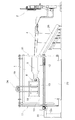
図1、図2及び図3に示すように、その表面が下側ほど鉄筋加工空間側に出た傾斜面に形成してある鉄板製の曲げ加工基盤1を設けると共に、鉄筋ピックアップ装置2により夫々定尺で複数本の鉄筋3の束から一本だけ摘み上げられて、鉄筋取り込み部4を通って鉄筋供給駆動部5によって供給される鉄筋3を、曲げ加工基盤1上でその表面に沿わせて鉄筋3を屈曲加工する屈曲加工部6を設けて、鉄筋加工装置が構成されている。
As shown in FIGS. 1, 2, and 3, a
前記屈曲加工部6には、図1、図2、図6及び図7に示すように、支点軸7と、その支点軸7の周りを回動操作自在な曲げローラ8とが、共に曲げ加工基盤1に直行する方向に出退(図6及び図7)すると共に、その基盤表面に沿って上下設定範囲内で変位自在に取付けられ、屈曲加工部6に供給された鉄筋3を切断する剪断刃9を、図8及び図9に示すように設けてある。
つまり、供給された鉄筋3に対して、上に曲げる場合は、鉄筋供給駆動部5から供給された鉄筋3に対して上側に支点軸7、下側に曲げローラ8が来るように支点軸7と曲げローラ8とを突出させて(図7から図6に突出変位)、支点軸7回りに上方に曲げローラ8を回動させ、下に曲げる場合は、鉄筋3に対して下側に支点軸7、上側に曲げローラ8が来るように支点軸7と曲げローラ8とを上下変位させてから突出させて、支点軸7回りに下方に曲げローラ8を回動させるように構成してあり、設定寸法及び設定回の曲げ加工後には、剪断刃9で切断するように構成してある。
As shown in FIGS. 1, 2, 6, and 7, the
That is, when bending upward with respect to the
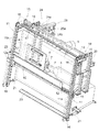
前記鉄筋加工装置には、更に、剪断刃9により切断されて曲げ加工基盤1の表面に沿って落下する鉄筋3を受け止め自在な鉄筋受け部材10を設け、鉄筋受け部材10を曲げ加工基盤1の表面に沿わせて上下に受け止め位置変更自在に支持する第1支持機構11を設け、鉄筋受け部材10で受け止めた鉄筋3を、曲げ加工基盤1に沿って搬送自在なベルト式コンベアで形成された搬送機構12、及び、受け取る鉄筋3を搬送機構12に沿った横側で搬送ガイドする側板13を、鉄筋受け部材10に設けて、屈曲加工部6の下方よりも離れた横方向に搬送するように構成してあると共に、曲げ加工基盤1の表面に沿う鉄筋3の曲げ可動を許容する隙間を、曲げ加工基盤1との間に空けて、屈曲加工部6による鉄筋3の曲げ可動範囲を覆う硬質覆い板14を、鉄板で形成して曲げ加工基盤1の表面に沿わせて設けてある。
Further, the reinforcing bar processing apparatus is provided with a reinforcing
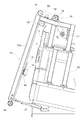
図1〜図5に示すように、前記第1支持機構11を構成するに、曲げ加工基盤1の上側から鉄筋受け部材10を吊り下げ支持する第1支持フレーム11aを設け、その第1支持フレーム11aにおける鉄筋受け部材10の支持位置を上下変位自在に構成すると共に、曲げ加工基盤1の上方から伝動チェーン15及びスプロケット16を介して駆動モーター17の駆動伝達により鉄筋受け部材10を上下変位動させる上下変位駆動機構18を設けてある。
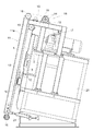
そして、第1枢支軸19を介して前記第1支持フレーム11aの上部を鉄筋加工装置本体側上部に取付けることにより、曲げ加工基盤1の表面に対する遠近方向に第1支持フレーム11aを揺動自在にし、その第1支持フレーム11aと鉄筋加工装置本体20との間に亘り、第1支持フレーム11aを駆動揺動する駆動装置として第1伸縮駆動シリンダ21を設けて、鉄筋受け部材10を、曲げ加工基盤1の表面に近接する鉄筋受け作用状態(図4)と、曲げ加工基盤1の表面から離間した非作用状態(図5)とに変更する状態切替機構を、第1支持機構11に設けてあり、その上で、屈曲加工部6による鉄筋3の屈曲加工操作時には鉄筋受け部材10を非作用状態(図5)にすると共に、剪断刃9による鉄筋切断時には、鉄筋受け部材10を鉄筋受け作用状態(図4)に駆動切り替えする第1制御装置を設けてある。
As shown in FIGS. 1 to 5, the
Then, by attaching the upper part of the
尚、前記第1制御装置による自動切り替え制御の他に、第1制御装置を制御解除状態にして、手動操作により、状態切替機構を切替操作できるようにもしてある。 In addition to the automatic switching control by the first control device, the first control device is brought into a control release state, and the state switching mechanism can be switched by a manual operation.
前記鉄筋受け部材10に設けた搬送機構12は、回転駆動モーター12aにより回転する無端チェーンの外表面に、受ける鉄筋3が跳ねないようにゴムベルトを一体化して、そのゴムベルト上に切断した加工鉄筋を受けるようにしてあり、図3に示すように、受け取った鉄筋3を横方向に曲げ加工基盤1に沿って搬送して鉄筋受け台22上に排出するようにしてある。
The
前記鉄筋受け台22上へ鉄筋3を排出する鉄筋受け部材10の終端部には、図13に示すように平面視で終端側ほど曲げ加工基盤1に近づくように取付けてあるガイド板23を設けてあり、曲げ加工鉄筋を確実に曲げ加工基盤1にもたれた姿勢で搬送して放出できるようにしてある。
このようにして搬送しながら放出することにより、放出時の鉄筋3の姿勢がそろい、複数本を束ねて取り出しやすくしてある。
As shown in FIG. 13, a
By discharging while transporting in this manner, the posture of the reinforcing
図1、図2、図3、図6〜図8に示すように、前記硬質覆い板14を曲げ加工基盤1の表面に対する遠近方向に移動自在に支持する第2支持機構24を設け、硬質覆い板14を曲げ加工基盤1に近接する覆い作用位置(図6、図8b)と、曲げ加工基盤1から遠ざかった覆い作用解除位置(図7、図8a)とに、第2支持機構24による支持位置を変更する支持位置変更操作装置25を設けてある。
つまり、前記硬質覆い板14を曲げ加工基盤1の上方から吊持ち支持する第2支持フレーム24aを設けると共に、その第2支持フレーム24aを曲げ加工基盤1の遠近方向に揺動自在に枢支する第2枢支軸24bを曲げ加工基盤1の本体の上部に取り付けて第2支持機構24を構成してあり、第2支持フレーム24aを揺動操作する第2伸縮駆動シリンダ25aを、本体と第2支持フレーム24aとに亘って取付けて支持位置変更操作装置25を構成してある。
As shown in FIGS. 1, 2, 3, and 6 to 8, a
In other words, a
前記硬質覆い板14は矩形の板で、その各辺には、鉄筋3が硬質覆い板14と曲げ加工基盤1との間に侵入しやすいように、外側ほど曲げ加工基盤1との隙間が大きくなる傾斜面部14aを設けてある。
また、第2支持フレーム24aに対して硬質覆い板14は、加工する鉄筋3の径に応じて硬質覆い板14と曲げ加工基盤1との間の隙間を変更可能に、シム板(図外)を介して着脱自在に取付けてある。
The
In addition, the
前記屈曲加工部6による鉄筋3の屈曲加工時に、硬質覆い板14を覆い作用位置(図6、図8b)に位置させると共に、鉄筋3の屈曲加工後の剪断刃9による切断時に、硬質覆い板14を覆い作用解除位置(図7、図8a)に変更するように支持位置変更操作装置25を作動制御する第2制御装置を設けてある。
At the time of bending the reinforcing
尚、前記第2制御装置による自動支持位置変更制御の他に、第2制御装置を制御解除状態にして、手動操作により、支持位置変更が出来るようにしてある。 In addition to the automatic support position change control by the second control device, the support position can be changed by manual operation by putting the second control device in a controlled release state.
前記鉄筋供給駆動部5は、図9〜図12に示すように、鉄筋3を取り込んで剪断刃9を設けた鉄筋切断装置28に鉄筋3をその一端側から送込み操作自在な第1鉄筋送込み装置26と第2鉄筋送込み装置27とを、鉄筋送込み方向に併設し、第1鉄筋送込み装置26と第2鉄筋送込み装置27とを、鉄筋3の送込み操作をする第1駆動状態から、鉄筋切断装置28に送り込んだ鉄筋3を、鉄筋残材放出部29に供給操作すべくその後端側から引き戻す第2駆動状態に切替可能に駆動切替機構を設けてある。
前記第1鉄筋送込み装置26には、正逆回転駆動自在な第1回転駆動ローラ26aとその第1回転駆動ローラ26aに鉄筋3を押付ける第1遊転ローラ26bとを設けると共に、第1回転駆動ローラ26aに第1遊転ローラ26bが近接することにより鉄筋後端が通過したことを検出する鉄筋後端検出機構を第1遊転ローラ26bに設け、前記第2鉄筋送込み装置27には、正逆回転駆動自在な第2回転駆動ローラ27bとその第2回転駆動ローラ27bに鉄筋3を押付ける第2遊転ローラ27bとを設けると共に、第2遊転ローラ27bにロータリーエンコーダーを取付けて鉄筋移動量計測機構に構成してある。
As shown in FIGS. 9 to 12, the reinforcing bar
The first reinforcing
前記第1鉄筋送込み装置26と前記第2鉄筋送込み装置27との間に、相対的に互いに遠近移動する一対の固定クランプ30aと上下可動クランプ30bとから成る鉄筋クランプ装置30を設けると共に、その鉄筋クランプ装置30を互いに近接移動するクランプ作動操作状態(図9)と、互いに遠ざかるクランプ非作動操作状態(図10)とに切替する状態切替機構を設けてある。
そして、前記状態切替機構によって、鉄筋後端通過後に鉄筋クランプ装置30をクランプ作動操作状態にすることによって(図11c)、鉄筋3を引戻して鉄筋3の後端を突き当てるストッパーに兼用化して、そのストッパーを鉄筋突き当て作用状態と非作用状態とに切替自在に構成してある。
Between the first reinforcing
And, by using the state switching mechanism, the
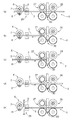
前記駆動切替機構により、定尺の鉄筋3を設定寸法及び設定回数曲げ加工するときは、第1駆動状態にするのであるが、加工鉄筋を切断後(図11a)、図11b〜図11eに示すように、第1駆動状態から第2駆動状態にして、最後に残る鉄筋残材を鉄筋残材放出部29に引戻す際に、残材の長さを設定長さに揃えて放出できるように、第3制御装置を次のように構成してある。
つまり、前記第1駆動状態の時にはストッパーを非作用状態に維持すると共に、後端検出機構による鉄筋後端の通過検出に基づいて、第2鉄筋送込み装置27と鉄筋移動量計測機構とによって第1鉄筋送込み装置26からの鉄筋後端の定量送り出し移動を行う第1ステップ操作指令(図11b)と、その第1ステップ操作指令後にストッパーに鉄筋突き当て作用状態にすべく切替指令を与えると共に、駆動切替機構に切替指令を与えて第2駆動状態にして鉄筋後端をストッパーに突き当てる第2ステップ操作指令(図11c)と、第2ステップ操作指令の後に、ストッパーを非作用状態にして鉄筋移動量計測機構による鉄筋移動量を計測しながら引き戻し操作をして、鉄筋後端から鉄筋先端側に鉄筋残材長さ設定手段により設定された長さ分寄った位置が鉄筋切断装置28に来た時に、引き戻し操作を一旦停止する第3ステップ操作指令(図11d)と、第3ステップ操作指令の後に鉄筋切断装置28の作動により鉄筋3をその残材用設定長さに切断する第4ステップ操作指令(図11e)と第4ステップ操作指令後、引き続き第2駆動状態を継続して残材用設定長さに切断した鉄筋3を鉄筋残材放出部29に供給する第5ステップ操作指令とを、順次発令するように第3制御装置を構成してある。
尚、前記第3制御装置は、鉄筋残材設定長さを変更調整自在に構成してあるばかりか、鉄筋残材を再利用しない場合は、その自動制御を解除して、鉄筋残材をそのまま設定長さに切り揃えないで放出できるようにもしてある。
When the fixed
That is, in the first driving state, the stopper is maintained in the non-operating state, and the second
In addition, the third control device is not only configured to be able to change and adjust the rebar remaining material setting length, but when the rebar remaining material is not reused, the automatic control is canceled and the rebar remaining material is left as it is. It is also possible to discharge without trimming to the set length.
〔別実施形態〕
以下に他の実施の形態を説明する。
[Another embodiment]
Other embodiments will be described below.
<1> 前記曲げ加工基盤1は、表面が傾斜面以外に、沿直面に形成してあってもよい。
<2> 前記搬送機構12は、ベルト式コンベア以外にチェーン式コンベアやローラー式コンベアであってもよい。
<3> 前記搬送機構12による搬送方向は、横方向以外に曲げ加工基盤1から遠ざかる方向であれば曲げ加工基盤1の面に交差する遠ざかる方向でも良い。
<4> 前記第1支持フレーム11aによる鉄筋受け部材10の支持は、揺動以外に、曲げ加工基盤の表面に対する遠近方向に平行移動自在に取り付けてあっても良い。
<5> 前記第2支持フレーム24aによる硬質覆い板14の支持は、揺動以外に、曲げ加工基盤1の遠近方向に平行移動自在に取り付けてあっても良い。
<6> 前記硬質覆い板14は、鉄板以外に他の硬質の材料であってもよい。
<7> 前記鉄筋クランプ装置30は、第1鉄筋送込み装置と第2鉄筋送込み装置の間のみならず、それらの下手側に配置してあっても良く、その場合は、ストッパーは、鉄筋クランプ装置とは別に第1鉄筋送込み装置と第2鉄筋送込み装置の間に設ける必要がある。
<1> The bending
<2> The
<3> The conveyance direction by the
<4> The support of the reinforcing
<5> The support of the
<6> The
<7> The reinforcing
尚、上述のように、図面との対照を便利にするために符号を記したが、該記入により本発明は添付図面の構成に限定されるものではない。また、本発明の要旨を逸脱しない範囲において、種々なる態様で実施し得ることは勿論である。 In addition, as mentioned above, although the code | symbol was written in order to make contrast with drawing convenient, this invention is not limited to the structure of an accompanying drawing by this entry. In addition, it goes without saying that the present invention can be carried out in various modes without departing from the gist of the present invention.
1 曲げ加工基盤
6 屈曲加工部
9 剪断刃
10 鉄筋受け部材
11 支持機構
11a 支持フレーム
12 搬送機構
14 硬質覆い板
19 枢支軸
24 支持機構
24a 支持フレーム
24b 枢支軸
25a 伸縮駆動シリンダ
26 第1鉄筋送込み装置
26a 第1駆動ローラ
26b 第1遊転ローラ
27 第2鉄筋送込み装置
27a 第2回転駆動ローラ
27b 第2遊転ローラ
28 鉄筋切断装置
29 鉄筋残材放出部
DESCRIPTION OF
Claims (3)
鉄筋送込み方向で上手側の前記第1鉄筋送込み装置に鉄筋後端検出機構を設けると共に、下手側の前記第2鉄筋送込み装置に鉄筋移動量計測機構を設け、
鉄筋残材の長さを設定自在な鉄筋残材長さ設定手段を設け、
前記第1鉄筋送込み装置と前記第2鉄筋送込み装置との間に、鉄筋の後端を突き当て自在なストッパーを配設すると共に、そのストッパーを鉄筋突き当て作用状態と非作用状態とに切替自在に構成し、
前記第1駆動状態の時には前記ストッパーを非作用状態に維持すると共に、前記後端検出機構による鉄筋後端の通過検出に基づいて、前記第2鉄筋送込み装置と前記鉄筋移動量計測機構とによって前記第1鉄筋送込み装置からの鉄筋後端の定量送り出し移動を行う第1ステップ操作指令と、
その第1ステップ操作指令後に前記ストッパーに鉄筋突き当て作用状態にすべく切替指令を与えると共に、前記駆動切替機構に切替指令を与えて前記第2駆動状態にして鉄筋後端を前記ストッパーに突き当てる第2ステップ操作指令と、
前記第2ステップ操作指令の後に前記ストッパーを非作用状態にして前記鉄筋移動量計測機構による鉄筋移動量を計測しながら引き戻し操作をして、鉄筋後端から鉄筋先端側に前記鉄筋残材長さ設定手段により設定された長さ分寄った位置が前記鉄筋切断装置に来た時に引き戻し操作を一旦停止する第3ステップ操作指令と、
前記第3ステップ操作指令の後に前記鉄筋切断装置の作動により鉄筋をその残材用設定長さに切断する第4ステップ操作指令と、
前記第4ステップ操作指令後、引き続き前記第2駆動状態を継続して残材用設定長さに切断した鉄筋を前記鉄筋残材放出部に供給する第5ステップ操作指令とを、順次発令する制御装置を設けてある鉄筋加工装置。 A first reinforcing bar feeding device and a second reinforcing bar feeding device that are provided with a reinforcing bar cutting device, take in a reinforcing bar from the outside through a reinforcing bar taking-in part, and can feed the reinforcing bar into the reinforcing bar cutting device from one end side thereof. Reinforcing the reinforcing bar fed to the reinforcing bar cutting device from the first driving state in which the first reinforcing bar feeding device and the second reinforcing bar feeding device are provided in the reinforcing bar feeding direction. A reinforcing bar machining apparatus provided with a drive switching mechanism that can be switched to the second drive state to be pulled back from the rear end side to supply to the remaining material discharge part,
A rebar rear end detection mechanism is provided in the first rebar feeding device on the upper side in the rebar feeding direction, and a rebar movement amount measuring mechanism is provided in the second rebar feeding device on the lower side,
Reinforcing bar remaining material length setting means that can freely set the length of reinforcing steel remaining material,
A stopper capable of abutting the rear end of the reinforcing bar is disposed between the first reinforcing bar feeding device and the second reinforcing bar feeding device, and the stopper is in a reinforcing bar abutting action state and a non-acting state. Switchable configuration,
In the first driving state, the stopper is kept in a non-acting state, and based on the detection of the passage of the rear end of the reinforcing bar by the rear end detecting mechanism, the second reinforcing bar feeding device and the reinforcing bar movement amount measuring mechanism A first step operation command for performing a fixed amount feeding movement of the rear end of the reinforcing bar from the first reinforcing bar feeding device;
After the first step operation command, a switching command is given to the stopper so as to enter a reinforcing bar abutting state, and a switching command is given to the drive switching mechanism to enter the second driving state so that the rear end of the reinforcing bar abuts against the stopper. A second step operation command;
After the second step operation command, the stopper is in an inoperative state and the pull-back operation is performed while measuring the rebar movement amount by the rebar movement amount measurement mechanism, so that the length of the remaining steel bar from the rear end of the rebar to the rebar front side. A third step operation command for temporarily stopping the pull back operation when the position close to the length set by the setting means comes to the reinforcing bar cutting device;
A fourth step operation command for cutting a reinforcing bar into its remaining material set length by the operation of the reinforcing bar cutting device after the third step operation command;
Control which issues sequentially the 5th step operation command which continues the 2nd drive state after the 4th step operation command, and supplies the rebar cut to the set length for remaining materials to the rebar remaining material discharge part. Rebar processing equipment provided with the device.
その鉄筋クランプ装置を互いに近接移動するクランプ作動操作状態と、互いに遠ざかるクランプ非作動操作状態とに切替する状態切替機構を設け、
前記鉄筋クランプ装置を、前記鉄筋切断装置による鉄筋切断操作時にクランプ作動操作状態にすると共に、前記第2ステップ操作指令時に前記ストッパーに兼用させるべくクランプ作動操作状態にする状態切替指令を、前記制御装置から状態切替機構に与えるように構成してある請求項1又は2記載の鉄筋加工装置。 Between the first reinforcing bar feeding device and the second reinforcing bar feeding device, there is provided a pair of reinforcing bar clamp devices that move relative to each other.
Provided with a state switching mechanism for switching between a clamp operation operation state in which the reinforcing bar clamping device is moved close to each other and a clamp non-operation operation state in which the rebar clamp device is moved away from each other,
A state switching command for setting the rebar clamp device to a clamp operation state at the time of a rebar cutting operation by the rebar cutting device and a clamp operation state to be used as the stopper at the time of the second step operation command, The reinforcing bar machining apparatus according to claim 1, wherein the rebar machining apparatus is configured to be supplied to the state switching mechanism.
Priority Applications (1)
| Application Number | Priority Date | Filing Date | Title |
|---|---|---|---|
| JP2008167831A JP5172497B2 (en) | 2008-06-26 | 2008-06-26 | Rebar processing equipment |
Applications Claiming Priority (1)
| Application Number | Priority Date | Filing Date | Title |
|---|---|---|---|
| JP2008167831A JP5172497B2 (en) | 2008-06-26 | 2008-06-26 | Rebar processing equipment |
Publications (2)
| Publication Number | Publication Date |
|---|---|
| JP2010005738A true JP2010005738A (en) | 2010-01-14 |
| JP5172497B2 JP5172497B2 (en) | 2013-03-27 |
Family
ID=41586797
Family Applications (1)
| Application Number | Title | Priority Date | Filing Date |
|---|---|---|---|
| JP2008167831A Active JP5172497B2 (en) | 2008-06-26 | 2008-06-26 | Rebar processing equipment |
Country Status (1)
| Country | Link |
|---|---|
| JP (1) | JP5172497B2 (en) |
Cited By (6)
| Publication number | Priority date | Publication date | Assignee | Title |
|---|---|---|---|---|
| KR101308245B1 (en) | 2010-10-21 | 2013-09-13 | 춘즈 머시너리 인더스트리 컴파니 리미티드 | Apparatus for producing blanks from a wire material |
| CN104128539A (en) * | 2014-07-25 | 2014-11-05 | 冯广建 | Automatic rebar cutting machine with sizing device and metering device |
| JP2016144822A (en) * | 2015-02-09 | 2016-08-12 | 奄美工業株式会社 | Cutting device of wire |
| CN110756704A (en) * | 2019-12-06 | 2020-02-07 | 义乌市鼎寒机械设备有限公司 | Construction bar cutter |
| KR102094327B1 (en) * | 2019-10-15 | 2020-03-27 | 비엠스틸 주식회사 | Round bar cutting apparatus |
| CN112247021A (en) * | 2020-09-30 | 2021-01-22 | 张进星 | Encoder sizing mechanism and control method thereof |
Families Citing this family (2)
| Publication number | Priority date | Publication date | Assignee | Title |
|---|---|---|---|---|
| CN104525625B (en) * | 2014-12-23 | 2016-08-24 | 冯广建 | A kind of parameter setting module |
| CN104760074B (en) * | 2015-03-31 | 2016-08-17 | 安徽省宁国市天成电气有限公司 | A kind of tubing diced system |
Citations (3)
| Publication number | Priority date | Publication date | Assignee | Title |
|---|---|---|---|---|
| JPS61127917U (en) * | 1985-01-30 | 1986-08-11 | ||
| JP2004106154A (en) * | 2002-09-20 | 2004-04-08 | Nippon Steel Corp | Multiple-line forming member cutting device and cutting-off method using device |
| JP2004330265A (en) * | 2003-05-09 | 2004-11-25 | Toyo Kensetsu Koki Kk | Reinforcing bar cutting device |
-
2008
- 2008-06-26 JP JP2008167831A patent/JP5172497B2/en active Active
Patent Citations (3)
| Publication number | Priority date | Publication date | Assignee | Title |
|---|---|---|---|---|
| JPS61127917U (en) * | 1985-01-30 | 1986-08-11 | ||
| JP2004106154A (en) * | 2002-09-20 | 2004-04-08 | Nippon Steel Corp | Multiple-line forming member cutting device and cutting-off method using device |
| JP2004330265A (en) * | 2003-05-09 | 2004-11-25 | Toyo Kensetsu Koki Kk | Reinforcing bar cutting device |
Cited By (8)
| Publication number | Priority date | Publication date | Assignee | Title |
|---|---|---|---|---|
| KR101308245B1 (en) | 2010-10-21 | 2013-09-13 | 춘즈 머시너리 인더스트리 컴파니 리미티드 | Apparatus for producing blanks from a wire material |
| CN104128539A (en) * | 2014-07-25 | 2014-11-05 | 冯广建 | Automatic rebar cutting machine with sizing device and metering device |
| CN104128539B (en) * | 2014-07-25 | 2016-04-27 | 冯广建 | A kind of reinforcing bar automatic cutting machine with scale metering device |
| JP2016144822A (en) * | 2015-02-09 | 2016-08-12 | 奄美工業株式会社 | Cutting device of wire |
| KR102094327B1 (en) * | 2019-10-15 | 2020-03-27 | 비엠스틸 주식회사 | Round bar cutting apparatus |
| CN110756704A (en) * | 2019-12-06 | 2020-02-07 | 义乌市鼎寒机械设备有限公司 | Construction bar cutter |
| CN112247021A (en) * | 2020-09-30 | 2021-01-22 | 张进星 | Encoder sizing mechanism and control method thereof |
| CN112247021B (en) * | 2020-09-30 | 2023-10-10 | 张进星 | Encoder sizing mechanism and control method thereof |
Also Published As
| Publication number | Publication date |
|---|---|
| JP5172497B2 (en) | 2013-03-27 |
Similar Documents
| Publication | Publication Date | Title |
|---|---|---|
| JP5172497B2 (en) | Rebar processing equipment | |
| EP2275215B1 (en) | Long-material conveying and positioning apparatus | |
| WO2016203628A1 (en) | Tape cutting processing device and processing method | |
| KR100943532B1 (en) | Cutting steel and bending device of four head steel automatic feeding system | |
| JP4448503B2 (en) | Equipment for cutting and joining band pieces of adhesive bands, especially cord bands, especially fiber cord bands | |
| TWI597144B (en) | Wire saw and method of processing a work by using the wire saw | |
| JP2005219059A (en) | Reinforcing bar feeder of reinforcing bar bending machine | |
| KR20070087199A (en) | Device for picking up, displacing and placing bands or strips of flexible material | |
| CZ2002987A3 (en) | Feeding device for cord strips | |
| KR100948373B1 (en) | Cutting steel and bending device of three head steel automatic feeding system | |
| KR20180045893A (en) | Wood semi-automatic cutting device | |
| JP5377896B2 (en) | Rebar processing equipment | |
| JP3509774B2 (en) | Rebar processing equipment | |
| JP5319181B2 (en) | Rebar processing equipment | |
| JP2021074730A (en) | Reinforcing-bar cutting device and reinforcing-bar cutting method | |
| JP4256865B2 (en) | Bar material feed amount detection device for bar material feeder | |
| JP5352662B2 (en) | Rubber material conveyor for tires | |
| JP2008063059A (en) | Pressure sensitive adhesive sheet sticking apparatus | |
| JP5025000B2 (en) | Sheet feeding device | |
| KR20150002536U (en) | Heavy board cutting device | |
| KR100757772B1 (en) | Cutting and conveying device for continuous sheet rubber and cutting and conveying system | |
| KR100844890B1 (en) | Apparatus for welding of iron strip for manufacturing of steel pipe | |
| JP2009226815A (en) | Cutting and supplying device of belt material and its method | |
| JP2002102960A (en) | Taking out method for reinforcement and taking out device therefor | |
| JP3948780B2 (en) | Waste material processing method and waste material processing apparatus for long material cutting device |
Legal Events
| Date | Code | Title | Description |
|---|---|---|---|
| A621 | Written request for application examination |
Free format text: JAPANESE INTERMEDIATE CODE: A621 Effective date: 20110622 |
|
| TRDD | Decision of grant or rejection written | ||
| A01 | Written decision to grant a patent or to grant a registration (utility model) |
Free format text: JAPANESE INTERMEDIATE CODE: A01 Effective date: 20121213 |
|
| A61 | First payment of annual fees (during grant procedure) |
Free format text: JAPANESE INTERMEDIATE CODE: A61 Effective date: 20121226 |
|
| R150 | Certificate of patent or registration of utility model |
Ref document number: 5172497 Country of ref document: JP Free format text: JAPANESE INTERMEDIATE CODE: R150 |
|
| R250 | Receipt of annual fees |
Free format text: JAPANESE INTERMEDIATE CODE: R250 |
|
| R250 | Receipt of annual fees |
Free format text: JAPANESE INTERMEDIATE CODE: R250 |
|
| R250 | Receipt of annual fees |
Free format text: JAPANESE INTERMEDIATE CODE: R250 |
|
| R250 | Receipt of annual fees |
Free format text: JAPANESE INTERMEDIATE CODE: R250 |
|
| R250 | Receipt of annual fees |
Free format text: JAPANESE INTERMEDIATE CODE: R250 |
|
| R250 | Receipt of annual fees |
Free format text: JAPANESE INTERMEDIATE CODE: R250 |
|
| R250 | Receipt of annual fees |
Free format text: JAPANESE INTERMEDIATE CODE: R250 |
|
| R250 | Receipt of annual fees |
Free format text: JAPANESE INTERMEDIATE CODE: R250 |
|
| R250 | Receipt of annual fees |
Free format text: JAPANESE INTERMEDIATE CODE: R250 |