JP2010005698A - Alloy casting having protective layer and method of making the same - Google Patents
Alloy casting having protective layer and method of making the same Download PDFInfo
- Publication number
- JP2010005698A JP2010005698A JP2009148181A JP2009148181A JP2010005698A JP 2010005698 A JP2010005698 A JP 2010005698A JP 2009148181 A JP2009148181 A JP 2009148181A JP 2009148181 A JP2009148181 A JP 2009148181A JP 2010005698 A JP2010005698 A JP 2010005698A
- Authority
- JP
- Japan
- Prior art keywords
- alloy
- casting
- mold
- protective layer
- aluminum
- Prior art date
- Legal status (The legal status is an assumption and is not a legal conclusion. Google has not performed a legal analysis and makes no representation as to the accuracy of the status listed.)
- Granted
Links
Images


Classifications
-
- C—CHEMISTRY; METALLURGY
- C23—COATING METALLIC MATERIAL; COATING MATERIAL WITH METALLIC MATERIAL; CHEMICAL SURFACE TREATMENT; DIFFUSION TREATMENT OF METALLIC MATERIAL; COATING BY VACUUM EVAPORATION, BY SPUTTERING, BY ION IMPLANTATION OR BY CHEMICAL VAPOUR DEPOSITION, IN GENERAL; INHIBITING CORROSION OF METALLIC MATERIAL OR INCRUSTATION IN GENERAL
- C23C—COATING METALLIC MATERIAL; COATING MATERIAL WITH METALLIC MATERIAL; SURFACE TREATMENT OF METALLIC MATERIAL BY DIFFUSION INTO THE SURFACE, BY CHEMICAL CONVERSION OR SUBSTITUTION; COATING BY VACUUM EVAPORATION, BY SPUTTERING, BY ION IMPLANTATION OR BY CHEMICAL VAPOUR DEPOSITION, IN GENERAL
- C23C8/00—Solid state diffusion of only non-metal elements into metallic material surfaces; Chemical surface treatment of metallic material by reaction of the surface with a reactive gas, leaving reaction products of surface material in the coating, e.g. conversion coatings, passivation of metals
- C23C8/06—Solid state diffusion of only non-metal elements into metallic material surfaces; Chemical surface treatment of metallic material by reaction of the surface with a reactive gas, leaving reaction products of surface material in the coating, e.g. conversion coatings, passivation of metals using gases
- C23C8/08—Solid state diffusion of only non-metal elements into metallic material surfaces; Chemical surface treatment of metallic material by reaction of the surface with a reactive gas, leaving reaction products of surface material in the coating, e.g. conversion coatings, passivation of metals using gases only one element being applied
- C23C8/10—Oxidising
-
- B—PERFORMING OPERATIONS; TRANSPORTING
- B22—CASTING; POWDER METALLURGY
- B22D—CASTING OF METALS; CASTING OF OTHER SUBSTANCES BY THE SAME PROCESSES OR DEVICES
- B22D19/00—Casting in, on, or around objects which form part of the product
- B22D19/08—Casting in, on, or around objects which form part of the product for building-up linings or coverings, e.g. of anti-frictional metal
-
- C—CHEMISTRY; METALLURGY
- C23—COATING METALLIC MATERIAL; COATING MATERIAL WITH METALLIC MATERIAL; CHEMICAL SURFACE TREATMENT; DIFFUSION TREATMENT OF METALLIC MATERIAL; COATING BY VACUUM EVAPORATION, BY SPUTTERING, BY ION IMPLANTATION OR BY CHEMICAL VAPOUR DEPOSITION, IN GENERAL; INHIBITING CORROSION OF METALLIC MATERIAL OR INCRUSTATION IN GENERAL
- C23C—COATING METALLIC MATERIAL; COATING MATERIAL WITH METALLIC MATERIAL; SURFACE TREATMENT OF METALLIC MATERIAL BY DIFFUSION INTO THE SURFACE, BY CHEMICAL CONVERSION OR SUBSTITUTION; COATING BY VACUUM EVAPORATION, BY SPUTTERING, BY ION IMPLANTATION OR BY CHEMICAL VAPOUR DEPOSITION, IN GENERAL
- C23C30/00—Coating with metallic material characterised only by the composition of the metallic material, i.e. not characterised by the coating process
-
- F—MECHANICAL ENGINEERING; LIGHTING; HEATING; WEAPONS; BLASTING
- F01—MACHINES OR ENGINES IN GENERAL; ENGINE PLANTS IN GENERAL; STEAM ENGINES
- F01D—NON-POSITIVE DISPLACEMENT MACHINES OR ENGINES, e.g. STEAM TURBINES
- F01D5/00—Blades; Blade-carrying members; Heating, heat-insulating, cooling or antivibration means on the blades or the members
- F01D5/12—Blades
- F01D5/28—Selecting particular materials; Particular measures relating thereto; Measures against erosion or corrosion
- F01D5/288—Protective coatings for blades
-
- F—MECHANICAL ENGINEERING; LIGHTING; HEATING; WEAPONS; BLASTING
- F05—INDEXING SCHEMES RELATING TO ENGINES OR PUMPS IN VARIOUS SUBCLASSES OF CLASSES F01-F04
- F05D—INDEXING SCHEME FOR ASPECTS RELATING TO NON-POSITIVE-DISPLACEMENT MACHINES OR ENGINES, GAS-TURBINES OR JET-PROPULSION PLANTS
- F05D2230/00—Manufacture
- F05D2230/20—Manufacture essentially without removing material
- F05D2230/21—Manufacture essentially without removing material by casting
-
- F—MECHANICAL ENGINEERING; LIGHTING; HEATING; WEAPONS; BLASTING
- F05—INDEXING SCHEMES RELATING TO ENGINES OR PUMPS IN VARIOUS SUBCLASSES OF CLASSES F01-F04
- F05D—INDEXING SCHEME FOR ASPECTS RELATING TO NON-POSITIVE-DISPLACEMENT MACHINES OR ENGINES, GAS-TURBINES OR JET-PROPULSION PLANTS
- F05D2230/00—Manufacture
- F05D2230/90—Coating; Surface treatment
-
- Y—GENERAL TAGGING OF NEW TECHNOLOGICAL DEVELOPMENTS; GENERAL TAGGING OF CROSS-SECTIONAL TECHNOLOGIES SPANNING OVER SEVERAL SECTIONS OF THE IPC; TECHNICAL SUBJECTS COVERED BY FORMER USPC CROSS-REFERENCE ART COLLECTIONS [XRACs] AND DIGESTS
- Y02—TECHNOLOGIES OR APPLICATIONS FOR MITIGATION OR ADAPTATION AGAINST CLIMATE CHANGE
- Y02T—CLIMATE CHANGE MITIGATION TECHNOLOGIES RELATED TO TRANSPORTATION
- Y02T50/00—Aeronautics or air transport
- Y02T50/60—Efficient propulsion technologies, e.g. for aircraft
Abstract
Description
本発明は、一般に合金鋳造品の分野に関し、具体的には液体冷却された合金鋳造品及びその製造方法に関する。 The present invention relates generally to the field of alloy castings, and more particularly to liquid-cooled alloy castings and methods for making the same.
一般に、超合金鋳造品は、約700℃より高い高温で溶融金属を鋳型に注入することによって鋳型内で形成される。通例、鋳型を液体金属浴に入れて、鋳型を冷却すると共に溶融体の凝固を促進する。液体金属浴中の金属は、比較的低い密度、低い融点(700℃未満)及び低い価格を有するのが望ましい。通例金属浴に使用される金属として、リチウム(186℃)、ナトリウム(98℃)、マグネシウム(650℃)、アルミニウム(660℃)、カリウム(63℃)、亜鉛(419℃)、インジウム(156℃)、スズ(232℃)、アンチモン(630℃)、セシウム(28℃)、テルル(450℃)などがある。リチウム、ナトリウム、カリウム及びセシウムのような金属は融解温度が低いが、非常に可燃性であるため安全上の問題を引き起こす。一方、亜鉛やアンチモンのような金属は蒸気圧が低く、そのためこれらの金属は蒸発して鋳造合金を汚染する危険がある。水銀のようなその他の金属の幾つかは毒性がある。アルミニウム及びスズは液体金属浴用として一般に好ましい金属である。アルミニウムはスズより融点が高い。すぐ分かるように、鋳造品と冷却剤(液体金属浴)との間の熱伝達は温度差の関数であり、従って、液体スズはその融点が低いことから、通例、鋳造品から熱を除去する点で液体アルミニウムより好ましい。 Generally, superalloy castings are formed in a mold by pouring molten metal into the mold at a high temperature above about 700 ° C. Typically, the mold is placed in a liquid metal bath to cool the mold and promote solidification of the melt. The metal in the liquid metal bath desirably has a relatively low density, low melting point (below 700 ° C.) and low price. The metals typically used in metal baths are lithium (186 ° C), sodium (98 ° C), magnesium (650 ° C), aluminum (660 ° C), potassium (63 ° C), zinc (419 ° C), indium (156 ° C). ), Tin (232 ° C.), antimony (630 ° C.), cesium (28 ° C.), tellurium (450 ° C.), and the like. Metals such as lithium, sodium, potassium and cesium have low melting temperatures but are very flammable and cause safety problems. On the other hand, metals such as zinc and antimony have low vapor pressures, so they can evaporate and contaminate the cast alloy. Some other metals such as mercury are toxic. Aluminum and tin are generally preferred metals for liquid metal baths. Aluminum has a higher melting point than tin. As can be readily seen, the heat transfer between the casting and the coolant (liquid metal bath) is a function of the temperature difference, and thus liquid tin typically removes heat from the casting because of its low melting point. This is preferable to liquid aluminum.
鋳造プロセスには非常に高い温度が関与するため、鋳型は亀裂を生じ易い。例えば、鋳型と鋳型の内部の超合金との間の熱膨張率の不一致の結果鋳型に亀裂が生じ得る。一端亀裂が生じると、液体スズが鋳型中に浸透し鋳造品を汚染する可能性がある。液体スズは鋳造品の表面を攻撃し、鋳造品の表面にピットを生成する。すぐ分かるように、ピットは鋳造品の表面から芯に向かって延びる欠陥である。ピットの生成はスズと超合金の成分との反応に起因し、その結果スズ化合物が生成する。 Due to the very high temperatures involved in the casting process, the mold is prone to cracking. For example, the mold can crack as a result of a mismatch in the coefficient of thermal expansion between the mold and the superalloy inside the mold. If cracks occur once, liquid tin can penetrate into the mold and contaminate the casting. Liquid tin attacks the surface of the casting and creates pits on the surface of the casting. As can be readily seen, the pit is a defect extending from the surface of the casting towards the core. The formation of pits is caused by the reaction between tin and superalloy components, resulting in the formation of tin compounds.
かかる鋳造品におけるピットの生成を回避するためのもっともらしい解決策は、亀裂を生じることがなく、従って液体金属が鋳造品表面と接触するのを防止する鋳型を製造することである。しかし、かかる鋳型を製造することは今まで可能ではなかった。さらに、かかる強固な鋳型は、鋳造品と鋳型との間の熱膨張の不一致に起因して鋳造品に亀裂を生じることがある。 A plausible solution to avoid the formation of pits in such castings is to produce a mold that does not crack and thus prevents liquid metal from coming into contact with the casting surface. However, it has not been possible to produce such a mold until now. Further, such a strong mold may crack the cast due to thermal expansion mismatch between the cast and the mold.
従って、鋳造品に対して液体金属の攻撃に耐性の層をもたらして、鋳造品におけるピットの生成を低減又は排除することによって、鋳造品の表面仕上げを改良する必要性がある。 Accordingly, there is a need to improve the surface finish of the casting by providing a layer that is resistant to liquid metal attack on the casting and reducing or eliminating pit formation in the casting.
本技術の1つの態様では、鋳造品の表面に保護層が設けられた合金鋳造品を提供する。保護層は、液体金属の攻撃に対して耐性であり、合金中に存在する元素の酸化物を含む。 One aspect of the present technology provides an alloy casting in which a protective layer is provided on the surface of the casting. The protective layer is resistant to liquid metal attack and includes oxides of elements present in the alloy.
本技術の別の態様では、鋳造品の表面に連続自然酸化物層が設けられたニッケル基合金の鋳造品を提供する。自然酸化物層は液体金属の攻撃に対して耐性である。 In another aspect of the present technology, a nickel-base alloy casting is provided in which a continuous natural oxide layer is provided on the surface of the casting. The native oxide layer is resistant to liquid metal attack.
本技術のさらに別の態様では、合金の鋳造品の表面に保護層を形成する方法を提供する。この方法では、鋳型に合金を配置し、合金の元素を酸化して鋳造品の表面に保護層を形成する。 In yet another aspect of the present technology, a method of forming a protective layer on the surface of an alloy casting is provided. In this method, an alloy is placed in a mold, and the elements of the alloy are oxidized to form a protective layer on the surface of the casting.
本技術の別の態様では、鋳造品上に酸化アルミニウム層を形成する方法を提供する。この方法は、鋳型の内面に内側皮膜が設けられた鋳型を準備し、鋳型に合金を配置することを含んでおり、合金中のアルミニウムの少なくとも一部分が、内側皮膜中の成分の一部分を還元して酸化アルミニウムを形成する。 In another aspect of the present technology, a method for forming an aluminum oxide layer on a cast article is provided. The method includes providing a mold having an inner coating on the inner surface of the mold and placing an alloy in the mold, wherein at least a portion of the aluminum in the alloy reduces a portion of the components in the inner coating. To form aluminum oxide.
本技術のさらに別の態様では、鋳造品上に酸化アルミニウム層を形成する方法を提供する。この方法では、鋳型を準備し、鋳型に合金を配置して鋳造品を形成し、鋳型に酸化性雰囲気を提供して合金中に存在するアルミニウムの少なくとも一部分を酸化する。 In yet another aspect of the present technology, a method for forming an aluminum oxide layer on a cast article is provided. In this method, a mold is prepared, an alloy is placed in the mold to form a casting, and an oxidizing atmosphere is provided to the mold to oxidize at least a portion of the aluminum present in the alloy.
本発明の上記及びその他の特徴、態様及び利点は、添付図面を参照して以下の詳細な説明を読むことによって、さらに良く理解されるであろう。図面全体を通して、類似の文字・符号は類似の部分を表す。 The above and other features, aspects and advantages of the present invention will be better understood by reading the following detailed description with reference to the accompanying drawings. Throughout the drawings, like characters / symbols represent like parts.
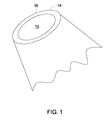
本明細書には、液体金属の攻撃に対して耐性である保護層を有する合金鋳造品及びその製造方法が記載されている。図1は、合金材料を含む合金鋳造品12及び保護層14の透視図である。本明細書で用いる「合金」という用語には、高温及び高い応力(引張、熱的、振動及び衝撃)に耐えることができる合金である超合金が包含される。幾つかの実施形態では、合金は、ニッケル、コバルト、鉄、チタン又はこれらの組合せを含み得る。合金はまた、比較的に少ない量の1種以上のモリブデン、タングステン、ニオブ又はその他の耐火性金属を含んでいてもよい。幾つかの実施形態では、合金はアルミニウムを含む。
This specification describes an alloy casting having a protective layer that is resistant to liquid metal attack and a method of manufacturing the same. FIG. 1 is a perspective view of an
幾つかの実施形態では、本技術は鋳造合金部品の表面仕上げの改良を容易にする。液体金属冷却鋳造法で製造された合金部品の従来の鋳造品は、合金と液体のスズ冷却剤との間の反応に起因するピットを含有する。本技術は、実質的に不透過性の保護層14を合金鋳造品12の表面16上に設けることによって、合金鋳造品12の表面16と液体金属冷却剤との間の反応を排除するか又は少なくとも低減する。幾つかの実施形態では、この保護層14は合金中に存在する元素の酸化物を含む。一例では、保護層14は酸化アルミニウムを含み得る。一実施形態では、ニッケル基合金は、鋳造品12の表面に設けられた酸化アルミニウム層のような連続自然酸化物層を含む。この実施形態では、自然酸化物層は液体金属の攻撃に対して耐性である。保護層14は、合金中のアルミニウムと反応性であるように選択された鋳型の内面の内側皮膜(フェースコート)と合金との反応によって又は合金のアルミニウムに対して酸化性であるが、合金のニッケル、コバルト又は耐火性金属に対しては比較的に反応性が低い雰囲気中で鋳造品を製造することによって、創成することができる。
In some embodiments, the technology facilitates improving the surface finish of cast alloy parts. Conventional castings of alloy parts produced by the liquid metal cooling casting process contain pits resulting from the reaction between the alloy and the liquid tin coolant. The present technology eliminates the reaction between the
幾つかの実施形態では、保護層14は液体金属の攻撃に対して耐性である酸化物層を含み得る。この実施形態では、保護層14は、液体金属が合金を汚染したり合金の金属と反応したりするのを防止する。保護層14は自然酸化物、すなわち合金中に存在する1種以上の元素の酸化物を含み得る。幾つかの実施形態では、酸化アルミニウムは酸化物層14の大部分を構成する。合金中の元素の1つとしてクロムが存在する場合、酸化クロムのような他の酸化物も形成され得る。
In some embodiments, the
通例、保護層14は、底面(鋳型の底部に近い方の面)及び鋳型側壁に隣接する側壁上に形成される。保護層14は鋳造品12の表面16全体で実質的に連続である。本明細書で用いる「実質的に連続」という用語は、鋳造品12の表面16の一部にしか保護層14が設けられていない可能性がある場合を具現化している。一部とは、数ミクロンの範囲であり得る。かかる不連続性は鋳造プロセス中制御され得ない幾つかの要因に基づいて起こり得る。例えば、不連続性は、酸化物を形成する酸素又は(酸化されることになる)金属がうまく利用できないことによって生じ得る。酸化物層の厚さは合金鋳造品の表面全体で均一であってもなくてもよい。鋳造品上の保護層の厚さは約0.5〜約50μmの範囲でよい。一実施形態では、保護層の少なくとも一部分は溶融体の鋳造と同時に形成される。一実施形態では、合金鋳造品は鋳造品の表面に連続自然酸化物層が設けられたニッケル基合金を含む。
Typically, the
幾つかの実施形態では、本技術の合金鋳造品はガスタービン用の翼形部、ガスタービン用の構造部品、ケーシング、リング、排気管及び燃焼部品、機体用の航空機構造物及び部品、自動車産業向けのターボチャージャーインペラー及びホイール、並びにその他の「高応力」部品に使用できる。 In some embodiments, the alloy castings of the present technology include an airfoil for a gas turbine, a structural component for a gas turbine, a casing, a ring, an exhaust pipe and a combustion component, an aircraft structure and component for an airframe, the automotive industry Turbocharger impellers and wheels, and other “high stress” parts.
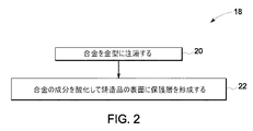
幾つかの実施形態では、合金鋳造品の表面に保護層を形成する方法を提供する。図2は、保護層を有する合金鋳造品を製造する代表的な方法を示すフローチャート18の図である。ブロック20で、合金を鋳型に注入する。ブロック22では、合金の元素を酸化して鋳造品の表面に保護層を形成する。図2に関連して記載した方法を実施するための代表的な装置は図3に示す。
In some embodiments, a method for forming a protective layer on a surface of an alloy casting is provided. FIG. 2 is a
図3に示されているように、装置24は液体金属浴28内に入れた鋳型26を含む。装置24は通例制御された雰囲気を有する容器内に入れられる。例えば、容器は炉を含んでいてもよい。鋳型26は、矢印32で示すように鋳型に注入される合金30を受容するようになっている。
As shown in FIG. 3, the
鋳型26はセラミック鋳型であり得る。例えば、鋳型26はジルコニア、ジルコン、シリカ、アルミナ又はこれらの組合せから製造される。鋳型26は合金30の高温に程良く耐えるように構成されている。すなわち、セラミック鋳型26は、1以上の小さい亀裂を生じる(図示してない)ことを除いて、合金30を受容する際に多かれ少なかれ一体化されたままでいる。合金30が凝固して鋳造品36を形成するプロセスは鋳型26内で底部38から頂部40に向かって進行する。鋳型に亀裂が生じた場合、亀裂を通って液体金属34が合金鋳造品中に浸透してこれを汚染する可能性がある。液体金属34の侵入による鋳造品36の汚染を防止するために、本技術の幾つかの実施形態では、鋳造品36の表面44上に保護層42を設置又は形成する。保護層42は、最初は鋳造品の底面46において生成し始め、鋳造品36の側壁48に沿って徐々に前進する。図4に関して詳細に説明するように、幾つかの実施形態では、鋳型26は、鋳型26の内面に皮膜50を含む。これらの実施形態では、合金30の1種以上の元素が鋳型26の内側皮膜50の1種以上の成分を還元して鋳造品36の表面46及び48上に保護層42を形成し得る。或いは、図5に関して詳細に述べるように、保護層42は、鋳造品36の凝固の直前、凝固中又は凝固後に酸化性雰囲気を鋳造品36に提供することによって形成することができる。こうして形成される鋳造品36は、主として鋳造品36に結合した保護層42を含む。しかし、幾つかの例においては、保護層42の一部分が鋳型26に結合していてもよい。鋳造品36の温度が低下するにつれて、鋳造品36は収縮し、保護層42の少なくとも一部分と共に鋳型壁から離れることがある。一実施形態では、保護層42の少なくとも一部分は鋳型26の表面に結合していない。
The
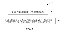
図4は、鋳造品上に保護層を設けるためのフローチャート54を図解する。ブロック56で、鋳型の内面に皮膜が設けられた鋳型を準備する。内側皮膜は合金の1種以上の元素に対して反応性であり得る。さらに、内側皮膜は合金のその他の元素に対して不活性又は非反応性であり得る。幾つかの実施形態では、内側皮膜はクロミア、ニオビア、チタニア、タンタラ、シリカ、ジルコン、イットリア又はこれらの組合せを含み得る。ブロック58において、鋳型に合金を配置する。一例では、合金中に存在するアルミニウムの一部分が内側皮膜中に存在する酸化ケイ素(シリカ)のような成分の少なくとも一部分を還元して、鋳造品の表面に酸化アルミニウム層を形成する。酸化アルミニウムに加えて、クロミアのような他の酸化物が酸化物層内に存在してもよい。
FIG. 4 illustrates a
図5は、鋳造品上に保護層を形成する代表的な方法を表すフローチャート60を図解する。ブロック62で、先に述べたように鋳型を準備するが、この鋳型はセラミック鋳型であり得る。ブロック64において、鋳型に合金を配置して鋳造品を形成する。ブロック66で、酸化性雰囲気を鋳型に導入して、合金中に存在するアルミニウムの少なくとも一部分を酸化する。酸化性雰囲気は、合金が凝固する直前、その間又はその後に導入し得る。一実施形態では、酸化性雰囲気は不活性キャリアで希釈された酸素源を含む。酸素源の非限定例としては、酸素、一酸化炭素、二酸化炭素、湿気又はこれらの組合せを挙げることができる。一例では、不活性キャリアはアルゴンを含み得る。一実施形態では、酸化性雰囲気は酸素源と不活性キャリアの混合物の総量の約2〜約20%をなす。一例では、酸化性雰囲気は約10%の一酸化炭素と約90%のアルゴンを含有する。
FIG. 5 illustrates a
以下の実施例で使用したセラミック鋳型はインベストメント鋳造産業で普通に行われている鋳型構築法を用いて実験室で製造した。鋳型を構築するのに用いたアルミナ、ジルコニア、ジルコン及びシリカのような成分はBrenntag Specialties社(米国ニュージャージー州サウス・プレインフィールド、クーリッジ・ストリート1000)及びNorton Materials社(米国マサチューセッツ州ウースター、ニュー・ボンド・ストリート1)のようなセラミック粉末供給業者から入手した。アルゴン、CO及びCO2ガスはAirgas East社(米国コネティカット州チェシャー、マッカンズランド・コート325)から入手した。方向性凝固炉はALD Vacuum Technology社(ドイツ連邦共和国ハーナウ、ヴィルヘルム・ローン・シュトラッセ35)から入手した。 The ceramic molds used in the following examples were manufactured in the laboratory using mold construction methods commonly practiced in the investment casting industry. Ingredients such as alumina, zirconia, zircon and silica used to construct the molds are Brentag Specialties (South Plainfield, NJ, Coolidge Street 1000) and Norton Materials (Worcester, Massachusetts, New Bond, USA). Obtained from a ceramic powder supplier such as Street 1). Argon, CO and CO 2 gas was obtained Airgas East Inc. (Conn Cheshire, Mecca lens Land Court 325) from. The directional solidification furnace was obtained from ALD Vacuum Technology (Hahnau, Germany, Wilhelm Lone Strasse 35).
実施例1
アルミナ系内面(フェースコート)を有するセラミック鋳型を使用した。鋳型の内面は、コロイド状シリカ中にアルミナ粉末を混合することによって調製したスラリーから調製した。暫定パターン(例えばワックス)をスラリー中に浸漬した後、この浸漬したてのパターン上に乾燥アルミナ粒子を篩い分け(sieving)して鋳型内面を形成した。スラリー浸漬とその後のアルミナ篩い分けの工程を二回繰り返した。これら2つの内面層の後、スラリー浸漬とそれに続くアルミナ篩い分けの工程をさらに10回繰り返したが、これらのバックアップ層にはより大きいアルミナ粒子を使用した。この際、スラリーと粒子の各コートを空気乾燥した後にその後のコートを設けた。蒸気オートクレーブを用いて暫定パターンを鋳型から除去した。その後、鋳型を約1000℃の温度で、鋳型を安定化するのに有効な時間焼成した。次に、このアルミナ系鋳型を、殊に鋳造中追加の冷却のための液体スズのポットを備えた方向性凝固炉内に入れた。方向性凝固炉において、鋳型を、最初にヒーター内で真空中約1500〜約1550℃の範囲の温度に予熱した。別途、投入量のニッケル基超合金をるつぼ内で溶融させ、この溶融した合金を、予熱した鋳型に真空雰囲気中で入れた。超合金は、7.5重量%のCo、9.75重量%のCr、4.2重量%のAl、7.5重量%のTi、0.5重量%のNb、4.8重量%のTa、1.5重量%のMo、6重量%のW、0.15重量%のHf、0.08重量%のC、0.009重量%のBを含み、残部がNiであった。次に、溶融した超合金で満たした鋳型をヒーターから引き出し、同様に真空雰囲気内で溶融したスズのポット中に浸漬した。引き出しの完了時に、液体スズで冷却された鋳型をスズポットから取り出した時、鋳型に亀裂が生じ鋳型に内部にスズが侵入している徴候を示していた。次いで、この鋳型を機械的に叩いて緩め、凝固した超合金鋳造品を露出させた。鋳造品はスズで覆われていたが、これは液体スズで増強された凝固プロセス中に鋳型に侵入した。その後、超合金鋳造品の回りのスズ材料を機械的手段と化学的洗浄によって除去した。スズ材料の化学的洗浄後、超合金鋳造品の表面を目視又は低い倍率の顕微鏡で検査して、表面ピットの形態にあるスズと金属表面の反応の程度を決定した。
Example 1
A ceramic mold having an alumina-based inner surface (face coat) was used. The inner surface of the mold was prepared from a slurry prepared by mixing alumina powder in colloidal silica. A temporary pattern (eg, wax) was immersed in the slurry, and then dried alumina particles were sieved on the freshly immersed pattern to form the mold inner surface. The process of slurry immersion and subsequent alumina sieving was repeated twice. After these two inner layers, the slurry dipping and subsequent alumina sieving steps were repeated 10 more times, but larger alumina particles were used for these backup layers. At this time, each coat of the slurry and particles was air-dried and then a subsequent coat was provided. The temporary pattern was removed from the mold using a steam autoclave. The mold was then fired at a temperature of about 1000 ° C. for a time effective to stabilize the mold. The alumina mold was then placed in a directional solidification furnace equipped with a pot of liquid tin for additional cooling, particularly during casting. In a directional solidification furnace, the mold was first preheated to a temperature in the range of about 1500 to about 1550 ° C. in a vacuum in a heater. Separately, an input amount of a nickel-base superalloy was melted in a crucible, and the molten alloy was placed in a preheated mold in a vacuum atmosphere. The superalloy consists of 7.5 wt% Co, 9.75 wt% Cr, 4.2 wt% Al, 7.5 wt% Ti, 0.5 wt% Nb, 4.8 wt% It contained Ta, 1.5 wt% Mo, 6 wt% W, 0.15 wt% Hf, 0.08 wt% C, 0.009 wt% B, with the balance being Ni. Next, the mold filled with the molten superalloy was pulled out of the heater and similarly immersed in a molten tin pot in a vacuum atmosphere. When the mold cooled with liquid tin was taken out of the tin pot upon completion of drawing, the mold showed cracks and showed signs that tin had entered the mold. The mold was then mechanically struck and loosened to expose the solidified superalloy casting. The casting was covered with tin, which entered the mold during the solidification process enhanced with liquid tin. Thereafter, the tin material around the superalloy casting was removed by mechanical means and chemical cleaning. After chemical cleaning of the tin material, the surface of the superalloy casting was inspected visually or with a low magnification microscope to determine the extent of reaction between the tin in the form of surface pits and the metal surface.
この実施例では、真空雰囲気中での鋳造にアルミナ系の内面を有する鋳型を使用したが、超合金鋳造品の表面には高度のスズピットが見られた。高度の表面ピットは望ましくないと考えられる。 In this example, a mold having an alumina-based inner surface was used for casting in a vacuum atmosphere, but high tin pits were observed on the surface of the superalloy casting. High surface pits are considered undesirable.
実施例2
この実施例では、実施例1と同様なアルミナ系内面を有するセラミック鋳型を液体スズ冷却方向性凝固実験に使用した。しかし、この第2の実施例では、鋳型予熱、超合金溶融、鋳型引き出し及びスズ浸漬の工程は、実施例1で用いたような真空中ではなくアルゴンと10%のCOを含む流動ガス混合物中で行った。アルゴン+10%CO混合物の流量は5立方フィート/時に設定した。
Example 2
In this example, a ceramic mold having the same alumina-based inner surface as in Example 1 was used for the liquid tin cooling directional solidification experiment. However, in this second example, the steps of mold preheating, superalloy melting, mold drawing and tin soaking are not in a vacuum as used in Example 1 but in a flowing gas mixture containing argon and 10% CO. I went there. The flow rate of the argon + 10% CO mixture was set at 5 cubic feet / hour.
アルゴン+10%COガス混合物を用いて得られた鋳造品も、超合金鋳造品の表面に高度のスズピットの生成を示すことが判明した。すなわち、この第2の実施例は、アルミナ系内面を有するセラミック鋳型を液体スズ冷却方向性凝固プロセスに使用した場合アルゴン+10%COガス雰囲気を使用しても超合金鋳造品の表面品質が改良されなかったことを示していた。 Castings obtained using an argon + 10% CO gas mixture were also found to show a high degree of tin pit formation on the surface of the superalloy casting. That is, in this second embodiment, when a ceramic mold having an alumina-based inner surface is used in a liquid tin cooling directional solidification process, the surface quality of the superalloy casting is improved even if argon + 10% CO gas atmosphere is used. It showed no.
実施例3
この実施例では、ケイ酸ジルコニウム(ジルコン)系内面(フェースコート)を有するセラミック鋳型を使用した。この実施例で用いた鋳型の内面は、コロイド状シリカ中にジルコン粉末を混合することによって形成されたスラリーから調製した。暫定パターンをスラリー中に浸漬した後乾燥アルミナ粒子を浸漬したてのパターン上に篩い分けして鋳型内面を形成した。スラリー浸漬とその後のアルミナ篩い分けの工程を二回繰り返した。2つの内面層の形成後、実施例1に記載した工程を使用して追加の10のバックアップ層を構築した。次に、この鋳型を約1000℃の温度で鋳型を安定化するのに有効な時間焼成した。
Example 3
In this example, a ceramic mold having a zirconium silicate (zircon) -based inner surface (face coat) was used. The inner surface of the mold used in this example was prepared from a slurry formed by mixing zircon powder in colloidal silica. The temporary pattern was dipped in the slurry, and then sieved on the freshly dipped alumina particle pattern to form the inner surface of the mold. The process of slurry immersion and subsequent alumina sieving was repeated twice. After the formation of the two inner layers, an additional 10 backup layers were constructed using the process described in Example 1. The mold was then fired at a temperature of about 1000 ° C. for a time effective to stabilize the mold.
このように、この実施例で使用したセラミック鋳型は、実施例1及び実施例2で用いたものとは内面の構成の点でのみ異なっていた。鋳型の内面はジルコン+コロイド状シリカ混合物を含んでいたが、実施例1及び実施例2で用いた鋳型の内面はアルミナ+コロイド状シリカ混合物を含んでいた。 Thus, the ceramic mold used in this example differed from that used in Example 1 and Example 2 only in the construction of the inner surface. The inner surface of the mold contained a zircon + colloidal silica mixture, while the inner surface of the mold used in Examples 1 and 2 contained an alumina + colloidal silica mixture.
ジルコン系内面を有するこの鋳型を、実施例1に記載した手順を用いて方向性凝固実験に使用した。得られた超合金鋳造品は、鋳造品の表面に中間の度合のスズピットを示すことが判明した。すなわち、この実施例は、ジルコン系鋳型を使用すると、液体スズ冷却方向性凝固プロセスを真空中で行った場合、超合金鋳造品の表面品質が中程度に改良されたことを示していた。 This mold with a zircon-based inner surface was used for directional solidification experiments using the procedure described in Example 1. The resulting superalloy casting was found to exhibit an intermediate degree of tin pits on the surface of the casting. That is, this example showed that using a zircon mold, the surface quality of the superalloy casting was moderately improved when the liquid tin cooling directional solidification process was performed in vacuum.
この実施例で生成した超合金鋳造品の表面の検査によって、超合金鋳造品の表面に幾らか連続的な酸化物層が形成したことが判明した。鋳造された超合金の表面に形成された酸化物層は、特に超合金材料と隣接する領域の、主としてアルミナであることが判明した。超合金鋳造品の表面に形成されたアルミナ系酸化物が、超合金鋳造品の表面で観察された低減したレベルのスズピットの原因であると結論された。 Inspection of the surface of the superalloy casting produced in this example revealed that a somewhat continuous oxide layer formed on the surface of the superalloy casting. It has been found that the oxide layer formed on the surface of the cast superalloy is mainly alumina, particularly in the region adjacent to the superalloy material. It was concluded that the alumina-based oxide formed on the surface of the superalloy casting was responsible for the reduced level of tin pits observed on the surface of the superalloy casting.
実施例4
この実施例では、実施例3と同様なジルコン系内面を有するセラミック鋳型を液体スズ冷却方向性凝固実験に使用した。また、鋳型予熱、超合金溶融、鋳型引き出し及びスズ浸漬の工程は、真空中ではなくアルゴンと10%のCOを含む流動ガス混合物中で行った。アルゴン+10%CO混合物の流量は5立方フィート/時に設定した。
Example 4
In this example, a ceramic mold having the same zircon-type inner surface as in Example 3 was used for the liquid tin cooling directional solidification experiment. Further, the steps of mold preheating, superalloy melting, mold drawing and tin immersion were performed in a flowing gas mixture containing argon and 10% CO, not in a vacuum. The flow rate of the argon + 10% CO mixture was set at 5 cubic feet / hour.
アルゴン+10%COガス混合物を用いて得られた鋳造品は、鋳造品の表面に低度のスズピットの生成を示すことが判明した。すなわち、この実施例は、アルゴン+10%COガス雰囲気を使用すると、液体スズ冷却方向性凝固プロセスでジルコン系内面を有するセラミック鋳型を使用した場合、超合金鋳造品の表面品質がさらに改良されたことを示していた。 Castings obtained using an argon + 10% CO gas mixture were found to show low tin pit formation on the surface of the cast. That is, in this example, when an argon + 10% CO gas atmosphere was used, the surface quality of the superalloy casting was further improved when a ceramic mold having a zircon-based inner surface was used in a liquid tin cooling directional solidification process. Was showing.
この実施例で生成した超合金鋳造品の表面の検査によって、超合金鋳造品の表面に連続的な酸化物の層が形成されたことが判明した。また、鋳造した超合金の表面に形成された酸化物層も、実施例3と同様に主としてアルミナであることが判明した。しかし、鋳造した超合金の表面に形成された酸化アルミニウム層は、前の実施例で見られた表面酸化物と比較してこの試料ではより連続的であることが分かった。このより連続的なアルミナ表面酸化物は、この実施例で観察されたより低いレベルのスズピットの原因であると結論された。 Inspection of the surface of the superalloy casting produced in this example revealed that a continuous oxide layer was formed on the surface of the superalloy casting. It was also found that the oxide layer formed on the surface of the cast superalloy was mainly alumina as in Example 3. However, the aluminum oxide layer formed on the surface of the cast superalloy has been found to be more continuous in this sample compared to the surface oxide found in the previous examples. It was concluded that this more continuous alumina surface oxide was responsible for the lower level of tin pits observed in this example.
連続的なアルミナ層は、スズ侵入と鋳造した超合金表面との直接の接触を防止し、従って金属表面のピット欠陥の形成の原因であるスズ−金属反応を防止するか又は少なくとも実反応の速度を低減するバッフル(邪魔板)として機能した。 The continuous alumina layer prevents tin intrusion and direct contact with the cast superalloy surface, thus preventing the tin-metal reaction that is responsible for the formation of pit defects on the metal surface or at least the rate of the actual reaction. Functioned as a baffle (baffle plate) to reduce
実施例5
この実施例では、実施例3及び実施例4と同様なジルコン系内面を有するセラミック鋳型を液体スズ冷却方向性凝固実験に使用した。しかし、この実施例では、鋳型予熱、超合金溶融、鋳型引き出し及びスズ浸漬の工程を、前の実施例に記載したような真空中又はアルゴン+10%COの混合物中ではなく、アルゴンと5%のCO2を含む流動ガス混合物中で行った。アルゴン+5%CO2混合物の流量は5立方フィート/時に設定した。
Example 5
In this example, a ceramic mold having the same zircon-type inner surface as in Examples 3 and 4 was used for the liquid tin cooling directional solidification experiment. However, in this example, the mold preheating, superalloy melting, mold drawing and tin dipping steps were not performed in a vacuum or a mixture of argon + 10% CO as described in the previous examples, but with 5% argon and 10% CO. It was performed in flowing gas mixture comprising CO 2. The flow rate of argon + 5% CO 2 mixture was set at 5 cubic feet / hour.
得られた鋳造品は、鋳造品の表面に低度のスズピットの生成を示すことが判明した。すなわち、この実施例は、アルゴン+5%CO2ガス雰囲気を使用したときも、ジルコン系内面を有するセラミック鋳型を液体スズ冷却方向性凝固プロセスに使用した場合、超合金鋳造品の表面品質が大きく改良されたことを示していた。このように、ここで観察されたアルゴン+5%CO2の混合物の有益な効果は、実施例4で観察されたアルゴン+10%COの混合物の効果と同様であった。 The resulting casting was found to exhibit low tin pit formation on the surface of the casting. That is, in this example, even when argon + 5% CO 2 gas atmosphere is used, when a ceramic mold having a zircon-based inner surface is used in a liquid tin cooling directional solidification process, the surface quality of the superalloy casting is greatly improved It was shown that. Thus, the beneficial effect of the argon + 5% CO 2 mixture observed here was similar to the effect of the argon + 10% CO mixture observed in Example 4.
実施例6
この実施例では、実施例3〜5と同様なジルコン系内面を有するセラミック鋳型を液体スズ冷却方向性凝固実験に使用した。しかし、この実施例では、鋳型予熱、超合金溶融、鋳型引き出し及びスズ浸漬の工程は、真空中でも、実施例4に記載したアルゴン+10%COの流動混合物でも又は実施例5に記載した流動アルゴン+5%CO2混合物中でもなく、CO2の流動ガス中で行った。
Example 6
In this example, a ceramic mold having the same zircon-type inner surface as in Examples 3 to 5 was used for the liquid tin cooling directional solidification experiment. However, in this example, the steps of mold preheating, superalloy melting, mold drawing and tin dipping can be performed in a vacuum, a flowing mixture of argon + 10% CO as described in Example 4 or flowing argon +5 as described in Example 5. % CO 2 mixture no in was carried out in a fluidized gas CO 2.
CO2ガスを用いて得られた鋳造品は、鋳造品の表面に高度のスズピットの生成を示すことが判明した。すなわち、この実施例は、実施例5の場合のようなキャリアとしてのアルゴンガスを使用しないCO2ガス雰囲気を使用すると、液体スズ冷却方向性凝固プロセスでの鋳造にジルコン系内面を有するセラミック鋳型を使用した場合でも、超合金鋳造品の表面品質を改良するのに有効でなかったことを示していた。 It has been found that castings obtained using CO 2 gas show a high degree of tin pit formation on the surface of the casting. That is, in this example, when a CO 2 gas atmosphere that does not use argon gas as a carrier as in Example 5 is used, a ceramic mold having a zircon-based inner surface for casting in a liquid tin cooling directional solidification process is used. Even when used, it was not effective in improving the surface quality of superalloy castings.
実施例7
この実施例では、実施例1及び実施例2と同様なアルミナ系内面を有するセラミック鋳型を使用したが、鋳造の前に鋳型の内面を処理する追加の手順を使用した。具体的には、この実施例で使用した鋳型は、最初に、実施例1に記載した鋳型の構築及び焼成手順を用いてアルミナ系内面を創成するように調製した。しかし、鋳型を実際に鋳造に使用する前に、この鋳型内面を、鋳物産業で「洗浄」として知られる追加の手順でさらに処理した。本明細書で用いる「洗浄」という用語は、様々に選択されたセラミック粒子を懸濁した水系溶液で鋳型の内面を濯ぐための手順をいう。本実施例では、アルミナ系内面を有する鋳型を、約10体積%のイットリア粒子を含有する溶液で洗浄した。その後、このイットリアで洗浄した鋳型を、液体スズで冷却される方向性凝固炉内での鋳造に使用する前に1000℃で焼成した。この実施例は鋳造は実施例1と同様に真空雰囲気中で行った。
Example 7
In this example, a ceramic mold with an alumina-based inner surface similar to Example 1 and Example 2 was used, but an additional procedure was used to treat the inner surface of the mold prior to casting. Specifically, the mold used in this example was first prepared to create an alumina-based inner surface using the mold construction and firing procedure described in Example 1. However, before the mold was actually used for casting, the inner surface of the mold was further processed with an additional procedure known as “cleaning” in the foundry industry. As used herein, the term “cleaning” refers to a procedure for rinsing the inner surface of a mold with an aqueous solution in which variously selected ceramic particles are suspended. In this example, a mold having an alumina-based inner surface was washed with a solution containing about 10% by volume of yttria particles. The mold washed with yttria was then fired at 1000 ° C. before being used for casting in a directional solidification furnace cooled with liquid tin. In this example, casting was performed in a vacuum atmosphere as in Example 1.
この実施例では、イットリアで洗浄したアルミナ系内面を有する鋳型を真空雰囲気における液体スズ冷却方向性凝固表面での鋳造に使用したが、得られた鋳造品は中間の度合のスズピットの生成を有することが判明した。すなわち、本実施例は、実施例1の結果と比較して、アルミナ系内面を有するイットリアで洗浄した鋳型を使用することに起因する超合金鋳造品の表面品質の改良を示していた。 In this example, a mold having an alumina-based inner surface cleaned with yttria was used for casting on a liquid tin cooling directionally solidified surface in a vacuum atmosphere, but the resulting casting had an intermediate degree of tin pit formation. There was found. That is, the present example showed an improvement in the surface quality of the superalloy cast product resulting from the use of a mold washed with yttria having an alumina-based inner surface, as compared with the result of Example 1.
実施例8
この実施例でも、実施例7と同様なイットリアで洗浄したアルミナ系内面を有するセラミック鋳型を液体スズ冷却方向性凝固実験に使用した。しかし、本実施例では、鋳型予熱、超合金溶融、鋳型引き出し及びスズ浸漬の工程を、実施例7で使用したような真空中ではなく、アルゴンと10%COからなる流動ガス混合物中で行った。アルゴン+10%CO混合物の流量は5立方フィート/時に設定した。
Example 8
Also in this example, the same ceramic mold having an alumina-based inner surface washed with yttria as in Example 7 was used for the liquid tin cooling directional solidification experiment. However, in this example, the steps of mold preheating, superalloy melting, mold drawing and tin dipping were performed in a flowing gas mixture of argon and 10% CO, not in the vacuum as used in Example 7. . The flow rate of the argon + 10% CO mixture was set at 5 cubic feet / hour.
アルゴン+10%COガス混合物を用いて得られた鋳造品は、超合金鋳造品の表面に低度のスズピットの生成を示すことが判明した。すなわち、本実施例は、アルゴン+10%COガス雰囲気を使用すると、イットリアで洗浄したアルミナ系内面を有するセラミック鋳型を液体スズ冷却方向性凝固プロセスに使用した場合、超合金鋳造品の表面品質がさらに改良されることを示していた。 Castings obtained with an argon + 10% CO gas mixture were found to show low tin pit formation on the surface of the superalloy casting. That is, in this example, when an argon + 10% CO gas atmosphere is used, when a ceramic mold having an alumina-based inner surface cleaned with yttria is used in a liquid tin cooling directional solidification process, the surface quality of the superalloy casting is further improved. It was shown to be improved.
以下の表に、上に詳細に記載した実施例1〜8の結果をまとめて示す。 The following table summarizes the results of Examples 1-8 detailed above.

これに反して、実施例3及び実施例4の結果は、ジルコン系内面を有するセラミック鋳型の方が液体スズ冷却方向性凝固プロセスに使用するのに望ましいことを示している。ジルコン系内面を有する鋳型は、鋳造プロセスを真空中で行う場合中程度の度合のスズピットを伴う超合金鋳造品を生成することができる。ジルコン系内面を有する鋳型は鋳造プロセスをアルゴン+10%COガスの流動混合物中で実施すると低度のスズピットを伴う超合金鋳造品を生成することができる。すなわち、アルゴンと10%COガスの流動混合物は、鋳造品の表面ピットを形成する傾向を低減することによって鋳造した表面の品質をさらに改良する雰囲気を創成する。 On the other hand, the results of Examples 3 and 4 show that ceramic molds with a zircon-based inner surface are more desirable for use in liquid tin cooling directional solidification processes. A mold having a zircon-based inner surface can produce a superalloy casting with a moderate degree of tin pits when the casting process is performed in vacuum. Molds with zircon-based inner surfaces can produce superalloy castings with low tin pits when the casting process is carried out in a flowing mixture of argon + 10% CO gas. That is, a flowing mixture of argon and 10% CO gas creates an atmosphere that further improves the quality of the cast surface by reducing the tendency to form surface pits in the casting.
実施例5及び実施例6の結果は、鋳造中の炉雰囲気の効果に関するさらなる教示を提供する。アルゴン+5%CO2の混合物はアルゴン+10%COの混合物と同様な有益な効果を有する。 The results of Example 5 and Example 6 provide further teaching regarding the effect of furnace atmosphere during casting. A mixture of argon + 5% CO 2 has the same beneficial effect as a mixture of argon + 10% CO 2.
実施例7及び実施例8の結果は、鋳型内面化学の効果に関するさらなる情報を提供する。アルミナ系内面を有する鋳型は実施例1及び実施例2に示されているように望ましくないが、イットリア洗浄による処理によって、アルミナ系内面を有する鋳型で調製した鋳造品の鋳造表面のスズ反応の度合を大幅に低減することができる。この改良は、イットリアで洗浄したをアルミナ系鋳型をアルゴンとCOの雰囲気と組み合わせて液体スズ冷却方向性凝固プロセスに使用した場合特に顕著である。従って、イットリア洗浄は、セラミック系を完全に変更することなく鋳型内面を修正するための代わりの方法を提供する。 The results of Example 7 and Example 8 provide further information regarding the effect of mold inner surface chemistry. A mold having an alumina-based inner surface is not desirable as shown in Examples 1 and 2, but the degree of tin reaction on the casting surface of a cast product prepared with a mold having an alumina-based inner surface by treatment with yttria cleaning. Can be greatly reduced. This improvement is particularly noticeable when the yttria cleaned alumina mold is used in a liquid tin cooling directional solidification process in combination with an argon and CO atmosphere. Thus, yttria cleaning provides an alternative way to modify the mold inner surface without completely changing the ceramic system.
本明細書では本発明の幾つかの特徴のみを例示し記載して来たが、多くの修正と変更が
当業者には明らかであろう。従って、特許請求の範囲は、本発明の真の思想内に入るかかる修正と変更を全て包含するものであると了解されたい。
While only certain features of the invention have been illustrated and described herein, many modifications and changes will be apparent to those skilled in the art. Accordingly, it is to be understood that the claims are intended to cover all such modifications and changes as fall within the true spirit of the invention.
12 鋳造品
14 保護層
16 鋳造品
18 フローチャート
20〜22 フローチャート18のの表面方法に関与する工程
24 保護を有する鋳造品を形成するための装置
26 鋳型
28 液体金属浴
30 合金
32 矢印
34 液体金属
36 鋳造品
38 鋳型の底部
40 鋳型の頂部
42 保護層
44 鋳造品の表面
46 鋳造品の底面
48 鋳造品の側壁
50 鋳型の内面の皮膜
54 フローチャート
56〜58 フローチャート54の方法に関与する工程
60 フローチャート
62〜66 フローチャート60の方法に関与する工程
12
Claims (25)
鋳型に合金を配置し、
合金の元素を酸化して、鋳造品の表面に保護層を形成する
ことを含んでなる方法。 A method of forming a protective layer on the surface of an alloy casting,
Place the alloy in the mold,
Oxidizing the alloy elements to form a protective layer on the surface of the casting.
鋳型の内面に皮膜が設けられた鋳型を準備し、
鋳型に合金を配置する
ことを含んでなり、合金中のアルミニウムの少なくとも一部分が皮膜中の成分の一部分を還元して酸化アルミニウムを形成する方法。 A method of forming an aluminum oxide layer on a casting,
Prepare a mold with a coating on the inner surface of the mold,
Placing the alloy in a mold, wherein at least a portion of the aluminum in the alloy reduces a portion of the components in the coating to form aluminum oxide.
鋳型を準備し、
鋳型に合金を配置して鋳造品を形成し、
鋳型に酸化性雰囲気を供給して合金中に存在するアルミニウムの少なくとも一部分を酸化する
ことを含んでなる方法。 A method of forming an aluminum oxide layer on a casting,
Prepare the mold,
An alloy is placed in the mold to form a casting,
Providing an oxidizing atmosphere to the mold to oxidize at least a portion of the aluminum present in the alloy.
Applications Claiming Priority (2)
| Application Number | Priority Date | Filing Date | Title |
|---|---|---|---|
| US12/145,459 US8906170B2 (en) | 2008-06-24 | 2008-06-24 | Alloy castings having protective layers and methods of making the same |
| US12/145,459 | 2008-06-24 |
Publications (2)
| Publication Number | Publication Date |
|---|---|
| JP2010005698A true JP2010005698A (en) | 2010-01-14 |
| JP5869747B2 JP5869747B2 (en) | 2016-02-24 |
Family
ID=41010381
Family Applications (1)
| Application Number | Title | Priority Date | Filing Date |
|---|---|---|---|
| JP2009148181A Expired - Fee Related JP5869747B2 (en) | 2008-06-24 | 2009-06-23 | Method for producing an alloy casting having a protective layer |
Country Status (5)
| Country | Link |
|---|---|
| US (1) | US8906170B2 (en) |
| EP (1) | EP2141263A3 (en) |
| JP (1) | JP5869747B2 (en) |
| CN (1) | CN101628331B (en) |
| RU (1) | RU2529134C2 (en) |
Cited By (1)
| Publication number | Priority date | Publication date | Assignee | Title |
|---|---|---|---|---|
| JP2016069702A (en) * | 2014-09-30 | 2016-05-09 | 日立金属株式会社 | Method for manufacturing nickel-based casting alloy |
Families Citing this family (24)
| Publication number | Priority date | Publication date | Assignee | Title |
|---|---|---|---|---|
| CN101965233B (en) * | 2008-03-05 | 2013-02-20 | 南线公司 | Niobium as a protective barrier in molten metals |
| US8652397B2 (en) | 2010-04-09 | 2014-02-18 | Southwire Company | Ultrasonic device with integrated gas delivery system |
| DK2556176T3 (en) | 2010-04-09 | 2020-05-04 | Southwire Co Llc | Ultrasonic degassing of molten metals |
| US8714233B2 (en) | 2011-03-29 | 2014-05-06 | General Electric Company | Casting process, materials and apparatus, and castings produced therewith |
| US9206704B2 (en) | 2013-07-11 | 2015-12-08 | General Electric Company | Cast CrMoV steel alloys and the method of formation and use in turbines thereof |
| EP3333273A1 (en) | 2013-11-18 | 2018-06-13 | Southwire Company, LLC | Ultrasonic probes with gas outlets for degassing of molten metals |
| JP6247977B2 (en) * | 2014-03-28 | 2017-12-13 | 株式会社クボタ | Cast products having an alumina barrier layer |
| US11674212B2 (en) | 2014-03-28 | 2023-06-13 | Kubota Corporation | Cast product having alumina barrier layer |
| CN104999054A (en) * | 2015-08-03 | 2015-10-28 | 东莞劲胜精密组件股份有限公司 | Method for combining different types of aluminum materials and combined part of different types of aluminum materials |
| US10233515B1 (en) | 2015-08-14 | 2019-03-19 | Southwire Company, Llc | Metal treatment station for use with ultrasonic degassing system |
| US10046389B2 (en) | 2015-12-17 | 2018-08-14 | General Electric Company | Method and assembly for forming components having internal passages using a jacketed core |
| US10137499B2 (en) | 2015-12-17 | 2018-11-27 | General Electric Company | Method and assembly for forming components having an internal passage defined therein |
| US10099283B2 (en) | 2015-12-17 | 2018-10-16 | General Electric Company | Method and assembly for forming components having an internal passage defined therein |
| US10099284B2 (en) | 2015-12-17 | 2018-10-16 | General Electric Company | Method and assembly for forming components having a catalyzed internal passage defined therein |
| US9968991B2 (en) | 2015-12-17 | 2018-05-15 | General Electric Company | Method and assembly for forming components having internal passages using a lattice structure |
| US10118217B2 (en) | 2015-12-17 | 2018-11-06 | General Electric Company | Method and assembly for forming components having internal passages using a jacketed core |
| US10099276B2 (en) | 2015-12-17 | 2018-10-16 | General Electric Company | Method and assembly for forming components having an internal passage defined therein |
| US9579714B1 (en) | 2015-12-17 | 2017-02-28 | General Electric Company | Method and assembly for forming components having internal passages using a lattice structure |
| US9987677B2 (en) | 2015-12-17 | 2018-06-05 | General Electric Company | Method and assembly for forming components having internal passages using a jacketed core |
| US10335853B2 (en) | 2016-04-27 | 2019-07-02 | General Electric Company | Method and assembly for forming components using a jacketed core |
| US10286450B2 (en) | 2016-04-27 | 2019-05-14 | General Electric Company | Method and assembly for forming components using a jacketed core |
| US11059098B2 (en) * | 2017-06-09 | 2021-07-13 | SAFI-Tech, Inc. | Direct printing and writing using undercooled metallic core-shell particles |
| CN109191459B (en) * | 2018-09-30 | 2022-02-11 | 东北大学 | Automatic identification and rating method for continuous casting billet macrostructure center segregation defect |
| CN112144008B (en) * | 2020-08-14 | 2021-10-22 | 中国科学院金属研究所 | Method for improving high-temperature-resistant liquid metal corrosion resistance of oxide dispersion strengthened steel through pre-oxidation |
Citations (13)
| Publication number | Priority date | Publication date | Assignee | Title |
|---|---|---|---|---|
| JPS5321042A (en) * | 1976-08-11 | 1978-02-27 | Onera (Off Nat Aerospatiale) | Method and device for casting formed member from refractory compound material |
| JPS57202940A (en) * | 1981-05-21 | 1982-12-13 | Alusuisse | Die with heat insulating protective film and method of coating its working surface |
| JPH0747444A (en) * | 1993-08-05 | 1995-02-21 | Mitsubishi Heavy Ind Ltd | Manufacture of casting mold for precise casting |
| JPH115151A (en) * | 1997-06-17 | 1999-01-12 | Honda Motor Co Ltd | Method for casting mold |
| JPH11241185A (en) * | 1998-02-27 | 1999-09-07 | Toyota Central Res & Dev Lab Inc | Production of titanium-aluminum series alloy excellent in oxidation resistant |
| JP2000247658A (en) * | 1999-02-23 | 2000-09-12 | Asahi Glass Co Ltd | Production of float glass |
| JP2001170757A (en) * | 1999-10-25 | 2001-06-26 | General Electric Co <Ge> | Oriented solidifying method cooled with liquid metal |
| JP2005320226A (en) * | 2004-04-06 | 2005-11-17 | Asahi Glass Co Ltd | Process and apparatus for producing float sheet glass |
| JP2006192544A (en) * | 2005-01-14 | 2006-07-27 | Sumitomo Electric Hardmetal Corp | Surface-coated cutting tool and its manufacturing method |
| JP2006312193A (en) * | 2005-05-09 | 2006-11-16 | Ishikawajima Harima Heavy Ind Co Ltd | Precision casting process and precision-cast product |
| JP2006326628A (en) * | 2005-05-25 | 2006-12-07 | Mitsubishi Electric Corp | Ceramic ladle and producing method therefor |
| JP2007119802A (en) * | 2005-10-25 | 2007-05-17 | Central Res Inst Of Electric Power Ind | Method for improving oxidation resistance of heat resistant metallic material and method for producing heat resistant metallic member |
| JP2007518881A (en) * | 2004-01-21 | 2007-07-12 | フォルシュングスツェントルム・ユーリッヒ・ゲゼルシャフト・ミット・ベシュレンクテル・ハフツング | Protective layer for aluminum-containing alloys for use at high temperatures and method for producing such a protective layer |
Family Cites Families (18)
| Publication number | Priority date | Publication date | Assignee | Title |
|---|---|---|---|---|
| US3972367A (en) | 1975-06-11 | 1976-08-03 | General Electric Company | Process for forming a barrier layer on ceramic molds suitable for use for high temperature eutectic superalloy casting |
| US3955616A (en) | 1975-06-11 | 1976-05-11 | General Electric Company | Ceramic molds having a metal oxide barrier for casting and directional solidification of superalloys |
| US4031945A (en) | 1976-04-07 | 1977-06-28 | General Electric Company | Process for making ceramic molds having a metal oxide barrier for casting and directional solidification of superalloys |
| US4316498A (en) * | 1980-01-18 | 1982-02-23 | Precision Metalsmiths, Inc. | Investment shell molding materials and processes |
| DE4125035A1 (en) | 1991-07-29 | 1993-02-04 | Truetzschler & Co | DEVICE ON A CARD FOR TEXTILE FIBERS, e.g. COTTON, CHEMICAL FIBERS AND THE LIKE |
| US5335717A (en) | 1992-01-30 | 1994-08-09 | Howmet Corporation | Oxidation resistant superalloy castings |
| US5660885A (en) | 1995-04-03 | 1997-08-26 | General Electric Company | Protection of thermal barrier coating by a sacrificial surface coating |
| CN1134329A (en) * | 1995-04-26 | 1996-10-30 | 鞍山钢铁学院 | Method for production of one-way solidified ingot |
| CN1074470C (en) * | 1997-07-03 | 2001-11-07 | 中国科学院金属研究所 | Method for preparing NiAl single crystal |
| RU2123909C1 (en) * | 1998-02-11 | 1998-12-27 | Всероссийский научно-исследовательский институт авиационных материалов | Method of producing castings with oriented crystallization and device for its embodiment |
| US6926928B2 (en) * | 2002-07-19 | 2005-08-09 | General Electric Company | Protection of a gas turbine component by a vapor-deposited oxide coating |
| US20040022662A1 (en) * | 2002-07-31 | 2004-02-05 | General Electric Company | Method for protecting articles, and related compositions |
| US6923935B1 (en) * | 2003-05-02 | 2005-08-02 | Brunswick Corporation | Hypoeutectic aluminum-silicon alloy having reduced microporosity |
| US7267158B2 (en) * | 2003-07-02 | 2007-09-11 | Alcoa Inc. | Control of oxide growth on molten aluminum during casting using a high moisture atmosphere |
| CN1307013C (en) * | 2003-10-24 | 2007-03-28 | 周照耀 | Method and equipment for successive co-orientation solidification casting and manufactured wire rod or plate and belt material |
| DE602006015904D1 (en) | 2006-03-24 | 2010-09-16 | Forschungszentrum Juelich Gmbh | Component with a protective layer |
| US7575042B2 (en) | 2006-03-30 | 2009-08-18 | General Electric Company | Methods for the formation of refractory metal intermetallic composites, and related articles and compositions |
| US7727318B2 (en) | 2007-01-09 | 2010-06-01 | General Electric Company | Metal alloy compositions and articles comprising the same |
-
2008
- 2008-06-24 US US12/145,459 patent/US8906170B2/en not_active Expired - Fee Related
-
2009
- 2009-06-17 EP EP09162915A patent/EP2141263A3/en not_active Withdrawn
- 2009-06-23 RU RU2009123991/02A patent/RU2529134C2/en not_active IP Right Cessation
- 2009-06-23 JP JP2009148181A patent/JP5869747B2/en not_active Expired - Fee Related
- 2009-06-24 CN CN200910163944.XA patent/CN101628331B/en not_active Expired - Fee Related
Patent Citations (13)
| Publication number | Priority date | Publication date | Assignee | Title |
|---|---|---|---|---|
| JPS5321042A (en) * | 1976-08-11 | 1978-02-27 | Onera (Off Nat Aerospatiale) | Method and device for casting formed member from refractory compound material |
| JPS57202940A (en) * | 1981-05-21 | 1982-12-13 | Alusuisse | Die with heat insulating protective film and method of coating its working surface |
| JPH0747444A (en) * | 1993-08-05 | 1995-02-21 | Mitsubishi Heavy Ind Ltd | Manufacture of casting mold for precise casting |
| JPH115151A (en) * | 1997-06-17 | 1999-01-12 | Honda Motor Co Ltd | Method for casting mold |
| JPH11241185A (en) * | 1998-02-27 | 1999-09-07 | Toyota Central Res & Dev Lab Inc | Production of titanium-aluminum series alloy excellent in oxidation resistant |
| JP2000247658A (en) * | 1999-02-23 | 2000-09-12 | Asahi Glass Co Ltd | Production of float glass |
| JP2001170757A (en) * | 1999-10-25 | 2001-06-26 | General Electric Co <Ge> | Oriented solidifying method cooled with liquid metal |
| JP2007518881A (en) * | 2004-01-21 | 2007-07-12 | フォルシュングスツェントルム・ユーリッヒ・ゲゼルシャフト・ミット・ベシュレンクテル・ハフツング | Protective layer for aluminum-containing alloys for use at high temperatures and method for producing such a protective layer |
| JP2005320226A (en) * | 2004-04-06 | 2005-11-17 | Asahi Glass Co Ltd | Process and apparatus for producing float sheet glass |
| JP2006192544A (en) * | 2005-01-14 | 2006-07-27 | Sumitomo Electric Hardmetal Corp | Surface-coated cutting tool and its manufacturing method |
| JP2006312193A (en) * | 2005-05-09 | 2006-11-16 | Ishikawajima Harima Heavy Ind Co Ltd | Precision casting process and precision-cast product |
| JP2006326628A (en) * | 2005-05-25 | 2006-12-07 | Mitsubishi Electric Corp | Ceramic ladle and producing method therefor |
| JP2007119802A (en) * | 2005-10-25 | 2007-05-17 | Central Res Inst Of Electric Power Ind | Method for improving oxidation resistance of heat resistant metallic material and method for producing heat resistant metallic member |
Cited By (1)
| Publication number | Priority date | Publication date | Assignee | Title |
|---|---|---|---|---|
| JP2016069702A (en) * | 2014-09-30 | 2016-05-09 | 日立金属株式会社 | Method for manufacturing nickel-based casting alloy |
Also Published As
| Publication number | Publication date |
|---|---|
| US20090314390A1 (en) | 2009-12-24 |
| US8906170B2 (en) | 2014-12-09 |
| EP2141263A2 (en) | 2010-01-06 |
| EP2141263A3 (en) | 2010-03-17 |
| CN101628331B (en) | 2015-04-01 |
| JP5869747B2 (en) | 2016-02-24 |
| RU2009123991A (en) | 2010-12-27 |
| RU2529134C2 (en) | 2014-09-27 |
| CN101628331A (en) | 2010-01-20 |
Similar Documents
| Publication | Publication Date | Title |
|---|---|---|
| JP5869747B2 (en) | Method for producing an alloy casting having a protective layer | |
| US8048365B2 (en) | Crucibles for melting titanium alloys | |
| US8062581B2 (en) | Refractory crucibles capable of managing thermal stress and suitable for melting highly reactive alloys | |
| US7761969B2 (en) | Methods for making refractory crucibles | |
| US8210240B2 (en) | Casting processes, casting apparatuses therefor, and castings produced thereby | |
| JP2008275305A (en) | Reinforced refractory crucible for melting titanium alloy | |
| JP2013136097A (en) | Method for making article having fine equiaxed grain structure | |
| US5335717A (en) | Oxidation resistant superalloy castings | |
| JP5437788B2 (en) | Casting mold and method for directional solidification process | |
| US20080292804A1 (en) | Methods for making refractory crucibles for melting titanium alloys | |
| JP6682762B2 (en) | Ni alloy casting product manufacturing method | |
| JP5925411B2 (en) | Casting process and yttria-containing facecoat material therefor | |
| Rakoczy et al. | The influence of shell mold composition on the as-cast macro-and micro-structure of thin-walled IN713C superalloy castings | |
| Varfolomeev et al. | Interaction of a Ceramic Casting Mold Material of the Al 2 O 3–Al 2 O 3 Composition with a Nickel-Based Superalloy | |
| TWI621485B (en) | Metal casting method | |
| RU2153955C2 (en) | Method for making thick-wall tube castings of refractory alloys | |
| JPS6027442A (en) | Casting mold | |
| JP2006312193A (en) | Precision casting process and precision-cast product | |
| JPH05305418A (en) | Production of cast ingot for strip by suction casting method |
Legal Events
| Date | Code | Title | Description |
|---|---|---|---|
| A621 | Written request for application examination |
Free format text: JAPANESE INTERMEDIATE CODE: A621 Effective date: 20120619 |
|
| A977 | Report on retrieval |
Free format text: JAPANESE INTERMEDIATE CODE: A971007 Effective date: 20130214 |
|
| A131 | Notification of reasons for refusal |
Free format text: JAPANESE INTERMEDIATE CODE: A131 Effective date: 20130305 |
|
| A601 | Written request for extension of time |
Free format text: JAPANESE INTERMEDIATE CODE: A601 Effective date: 20130605 |
|
| A602 | Written permission of extension of time |
Free format text: JAPANESE INTERMEDIATE CODE: A602 Effective date: 20130610 |
|
| A601 | Written request for extension of time |
Free format text: JAPANESE INTERMEDIATE CODE: A601 Effective date: 20130704 |
|
| A602 | Written permission of extension of time |
Free format text: JAPANESE INTERMEDIATE CODE: A602 Effective date: 20130709 |
|
| A601 | Written request for extension of time |
Free format text: JAPANESE INTERMEDIATE CODE: A601 Effective date: 20130801 |
|
| A602 | Written permission of extension of time |
Free format text: JAPANESE INTERMEDIATE CODE: A602 Effective date: 20130806 |
|
| A521 | Request for written amendment filed |
Free format text: JAPANESE INTERMEDIATE CODE: A523 Effective date: 20130905 |
|
| A131 | Notification of reasons for refusal |
Free format text: JAPANESE INTERMEDIATE CODE: A131 Effective date: 20140311 |
|
| A601 | Written request for extension of time |
Free format text: JAPANESE INTERMEDIATE CODE: A601 Effective date: 20140610 |
|
| A602 | Written permission of extension of time |
Free format text: JAPANESE INTERMEDIATE CODE: A602 Effective date: 20140613 |
|
| A601 | Written request for extension of time |
Free format text: JAPANESE INTERMEDIATE CODE: A601 Effective date: 20140710 |
|
| A602 | Written permission of extension of time |
Free format text: JAPANESE INTERMEDIATE CODE: A602 Effective date: 20140715 |
|
| A521 | Request for written amendment filed |
Free format text: JAPANESE INTERMEDIATE CODE: A523 Effective date: 20140811 |
|
| A131 | Notification of reasons for refusal |
Free format text: JAPANESE INTERMEDIATE CODE: A131 Effective date: 20150224 |
|
| A521 | Request for written amendment filed |
Free format text: JAPANESE INTERMEDIATE CODE: A523 Effective date: 20150522 |
|
| A02 | Decision of refusal |
Free format text: JAPANESE INTERMEDIATE CODE: A02 Effective date: 20150609 |
|
| A521 | Request for written amendment filed |
Free format text: JAPANESE INTERMEDIATE CODE: A523 Effective date: 20151008 |
|
| A911 | Transfer to examiner for re-examination before appeal (zenchi) |
Free format text: JAPANESE INTERMEDIATE CODE: A911 Effective date: 20151124 |
|
| TRDD | Decision of grant or rejection written | ||
| A01 | Written decision to grant a patent or to grant a registration (utility model) |
Free format text: JAPANESE INTERMEDIATE CODE: A01 Effective date: 20151215 |
|
| A61 | First payment of annual fees (during grant procedure) |
Free format text: JAPANESE INTERMEDIATE CODE: A61 Effective date: 20160108 |
|
| R150 | Certificate of patent or registration of utility model |
Ref document number: 5869747 Country of ref document: JP Free format text: JAPANESE INTERMEDIATE CODE: R150 |
|
| R250 | Receipt of annual fees |
Free format text: JAPANESE INTERMEDIATE CODE: R250 |
|
| R250 | Receipt of annual fees |
Free format text: JAPANESE INTERMEDIATE CODE: R250 |
|
| R250 | Receipt of annual fees |
Free format text: JAPANESE INTERMEDIATE CODE: R250 |
|
| R250 | Receipt of annual fees |
Free format text: JAPANESE INTERMEDIATE CODE: R250 |
|
| LAPS | Cancellation because of no payment of annual fees |