JP2010004389A - Watthour meter and power line carrier communication system - Google Patents
Watthour meter and power line carrier communication system Download PDFInfo
- Publication number
- JP2010004389A JP2010004389A JP2008162267A JP2008162267A JP2010004389A JP 2010004389 A JP2010004389 A JP 2010004389A JP 2008162267 A JP2008162267 A JP 2008162267A JP 2008162267 A JP2008162267 A JP 2008162267A JP 2010004389 A JP2010004389 A JP 2010004389A
- Authority
- JP
- Japan
- Prior art keywords
- power line
- carrier communication
- line carrier
- home
- communication unit
- Prior art date
- Legal status (The legal status is an assumption and is not a legal conclusion. Google has not performed a legal analysis and makes no representation as to the accuracy of the status listed.)
- Granted
Links
Images


Abstract
Description
本発明は、電力量計及び電力線搬送通信システムに関するものである。 The present invention relates to a watt-hour meter and a power line carrier communication system.
近年、電力会社から供給される商用電力を配電する電力線を通信媒体として用い、住宅間で通信を行ったり、宅内に設置された電気機器を制御したりする電力線搬送通信システムが知られている。 2. Description of the Related Art In recent years, there is known a power line carrier communication system that uses a power line that distributes commercial power supplied from an electric power company as a communication medium, performs communication between houses, and controls electric devices installed in a house.
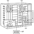
図11、図12は、従来の電力線搬送通信システムの全体構成図を示している。図11に示すように、電力量計(WHM)101は、マンション等の集合住宅の各住戸に設置され、各住戸に供給される電力量を計測する。具体的には、電力量計101は、変圧トランス104と宅内分電盤102とを接続する電力線上に設置されている。
11 and 12 show an overall configuration diagram of a conventional power line carrier communication system. As shown in FIG. 11, a watt-hour meter (WHM) 101 is installed in each dwelling unit of an apartment house such as a condominium and measures the amount of power supplied to each dwelling unit. Specifically, the watt-
変圧トランス104は、電力会社から供給される商用電力を高圧−低圧変換して電力量計101を介して宅内分電盤102に出力する。宅内分電盤102は、電力量計101の下流側に接続され、配下にはコンセント105を介して電気機器103及び端末106が接続されている。
The
このように構成された電力線搬送通信システムにおいては、端末106と電力線に接続された住戸外の通信機器107との間で電力線搬送通信信号(PLC信号)が送受される。
In the power line carrier communication system configured as described above, a power line carrier communication signal (PLC signal) is transmitted and received between the
なお、本願発明に関連する技術として、特許文献1には、第1ネットワーク10からのPLC信号を抽出する第1信号抽出部3と、第2ネットワーク20からのPLC信号を抽出する第2抽出部4と、制御部6とを備える電力線搬送通信装置1が開示されている。この電力線搬送通信装置1においては、制御部6により、第1信号抽出部3を経由して第1ネットワーク10から第2ネットワーク20内にある対象機器への制御信号が受信されると、この制御信号が第2のネットワークに送信される(段落[0018])。
しかしながら、図11及び図12の構成において、住宅内に、低インピーダンスかつ高雑音の電気機器103が接続されると、電気機器103で生じた雑音が電力線に流れ、電力線搬送通信が困難になる虞がある。また、特許文献1の電力線搬送通信装置は、電力量計に関するものではない。
However, in the configuration shown in FIGS. 11 and 12, when a low impedance and high noise
本発明の目的は、信頼性の高い電力線搬送通信を実現することができる電力量計及びその電力量計を用いた電力線搬送通信システムを提供することである。 The objective of this invention is providing the watt-hour meter which can implement | achieve highly reliable power-line carrier communication, and the power-line carrier communication system using the watt-hour meter.
(1)本発明による電力線搬送通信システムは、変圧トランスにより降圧された商用電力を宅内に供給する幹線系電力線と、前記幹線系電力線に接続された電力量計と、前記電力量計に接続され、前記幹線系電力線を介して供給される商用電力を、宅内分電盤の配下に接続された電気機器に供給する宅内系電力線とを備え、前記電力量計は、前記幹線系電力線を介して電力線搬送通信を行う第1の通信部と、前記宅内系電力線を介して電力線搬送通信を行う第2の通信部とを備えることを特徴とする。 (1) A power line carrier communication system according to the present invention is connected to a main power line for supplying commercial power stepped down by a transformer to a home, a watt hour meter connected to the main power line, and the watt hour meter. A power line for supplying commercial power supplied via the main power line to an electrical device connected to a sub-distribution board, and the watt-hour meter is connected via the main power line. A first communication unit that performs power line carrier communication and a second communication unit that performs power line carrier communication via the in-home power line are provided.
この構成によれば、電力量計は、幹線系電力線を用いて電力線搬送通信を行う第1の通信部と、宅内系電力線を用いて電力線搬送通信を行う第2の通信部とを備えている。そのため、宅内に低インピーダンスかつ高雑音の電気機器が接続されたとしても、信頼性の高い電力線搬送通信を実現することができる。 According to this configuration, the watt-hour meter includes a first communication unit that performs power line carrier communication using a trunk power line and a second communication unit that performs power line carrier communication using a home power line. . Therefore, even when a low-impedance and high-noise electric device is connected to the home, highly reliable power line carrier communication can be realized.
(2)前記第1の通信部は、前記幹線系電力線からの通信信号を前記宅内系電力線に中継し、前記第2の通信部は、前記宅内系電力線からの通信信号を前記幹線系電力線に中継することが好ましい。 (2) The first communication unit relays a communication signal from the trunk power line to the home power line, and the second communication unit sends a communication signal from the home power line to the main power line. It is preferable to relay.
この構成によれば、第1及び第2の通信部は中継機能を備えているため、幹線系電力線から宅内系電力線に送信される通信信号及び宅内系電力線から幹線系電力線に送信される通信信号は、減衰分が増幅されるため、通信の信頼性を向上させることができる。 According to this configuration, since the first and second communication units have a relay function, a communication signal transmitted from the main power line to the home power line and a communication signal transmitted from the home power line to the main power line. Since the attenuation is amplified, the reliability of communication can be improved.
(3)前記第1の通信部は、所定の低速伝送帯域で電力線搬送通信を行い、前記第2の通信部は、前記低速伝送帯域よりも高い所定の高速伝送帯域で電力線搬送通信を行うことが好ましい。 (3) The first communication unit performs power line carrier communication in a predetermined low-speed transmission band, and the second communication unit performs power line carrier communication in a predetermined high-speed transmission band higher than the low-speed transmission band. Is preferred.
この構成によれば、伝送距離の長い幹線系の電力線搬送通信には、低速伝送帯域の電力線搬送通信が用いられ、伝送距離の短い宅内系の電力線搬送通信には、高速伝送帯域の電力線搬送通信が用いられているため、通信の信頼性を向上させることができる。 According to this configuration, the power line carrier communication in the low speed transmission band is used for the power line carrier communication of the trunk line system having a long transmission distance, and the power line carrier communication in the high speed transmission band is used for the power line carrier communication in the home system of a short transmission distance Therefore, communication reliability can be improved.
(4)前記電力量計は、前記第1の通信部と前記第2の通信部との間に接続された濾波器を備えることが好ましい。 (4) Preferably, the watt-hour meter includes a filter connected between the first communication unit and the second communication unit.
この構成によれば、第1の通信部と第2の通信部との間に濾波器が接続されているため、幹線側の電力線搬送通信と宅内側の電力線搬送通信との信号干渉が抑制され、通信の信頼性を向上させることができる。 According to this configuration, since the filter is connected between the first communication unit and the second communication unit, signal interference between the power line carrier communication on the main line side and the power line carrier communication on the inside of the house is suppressed. Communication reliability can be improved.
(5)前記宅内系電力線に接続され、前記電気機器を制御する情報盤を更に備えることが好ましい。 (5) It is preferable to further comprise an information panel connected to the in-home power line and controlling the electrical equipment.
この構成によれば、情報盤により電気機器を一括制御したり、電気機器を監視したりすることができる。 According to this configuration, it is possible to collectively control electrical devices or monitor electrical devices using the information board.
(6)前記情報盤は、公衆回線網に接続されていることが好ましい。 (6) The information board is preferably connected to a public line network.
この構成によれば、情報盤により収集された電力量情報等の情報を公衆回線網を介して外部に出力することが可能となる。 According to this configuration, it is possible to output information such as the electric energy information collected by the information board to the outside via the public line network.
(7)前記公衆回線網を介して前記情報盤に接続され、前記電力量計により計測された電力量情報を収集するサーバを更に備えることが好ましい。 (7) It is preferable to further include a server connected to the information panel via the public line network and collecting power amount information measured by the power meter.
この構成によれば、サーバは電力量計により計測された電力量情報を収集することができる。 According to this configuration, the server can collect the energy information measured by the energy meter.
(8)前記サーバは、前記電力量情報に基づき、前記電気機器を制御するための情報を前記公衆回線網を介して前記情報盤に送信することが好ましい。 (8) It is preferable that the server transmits information for controlling the electric device to the information board via the public line network based on the power amount information.
この構成によれば、サーバは、電気機器を遠隔制御したり、遠隔監視したりすることが
できる。
According to this configuration, the server can remotely control or remotely monitor the electric device.
(9)本発明による電力量計は、請求項1〜8のいずれかに記載された電力線搬送通信システムに用いられる電力量計である。
(9) The watt-hour meter according to the present invention is a watt-hour meter used in the power line carrier communication system according to any one of
この構成によれば、(1)〜(8)のいずれかに記載の電力線搬送通信システムに使用される電力量計を提供することができる。 According to this structure, the watt-hour meter used for the power line carrier communication system in any one of (1)-(8) can be provided.
本発明によれば、宅内に低インピーダンスかつ高雑音の電気機器が接続されたとしても、信頼性の高い電力線搬送通信を実現することができる。 ADVANTAGE OF THE INVENTION According to this invention, even if a low impedance and high noise electric equipment is connected in the house, highly reliable power line carrier communication can be realized.
(実施の形態1)
図1は、本発明の実施の形態1による電力線搬送通信システムの全体構成図である。図1に示すように電力線搬送通信システムは、変圧トランスT1により降圧された商用電力を宅内に供給する幹線系電力線PL1と、幹線系電力線PL1に接続された電力量計(WHM:watt hour meter)10と、電力量計10に接続され、幹線系電力線PL1を介して供給される商用電力を、宅内分電盤20の配下に接続された電気機器40及び端末50に供給する宅内系電力線PL2と、宅内分電盤20とを備えている。
(Embodiment 1)
FIG. 1 is an overall configuration diagram of a power line carrier communication system according to
電気機器40は及び端末50はコンセント30を介して宅内分電盤20に接続されている。電気機器40は、例えばエアコンやテレビ等の家庭用電化製品により構成される。
The
端末50は、例えば電力線搬送通信が可能な通信装置を備えるパソコンにより構成される。本実施の形態においては、端末50は、電力線搬送通信を用いて幹線系電力線PL1を介して住戸外に接続された通信機器と通信を行う。
The
宅内分電盤20は、主幹ブレーカ及び分岐ブレーカ等を備え、宅内系電力線PL2に過電流が流れた場合、商用電力の宅内側への供給を遮断する。
The in-
なお、図1では、宅内分電盤には4台の電気機器40が接続されているが、これに限定されず、n(nは1以上の整数)台の電気機器40を接続してもよい。また、図1では、宅内分電盤20には1台の端末50が接続されているが、これに限定されず、m(mは1以上の整数)台の端末50を接続してもよい。また、図1では、電気機器40はコンセント30を介して宅内分電盤20に接続されているが、電気機器40の種類に応じて、コンセント30を介することなく、直接、宅内分電盤20に接続してもよい。
In FIG. 1, four
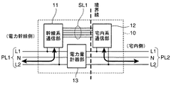
図2は、図1に示す電力量計10のブロック図である。図2に示すように電力量計10は、幹線系通信部11(第1の通信部の一例)、宅内系通信部12(第2の通信部の一例)、及び電力量計器部13を備えている。
FIG. 2 is a block diagram of the watt-
幹線系通信部11は、送信対象のデータをAC重畳してPLC信号を生成する結合回路と、PLC信号を指定された波形に成形するための送信アンプ及び受信フィルタ部を備えるアナログ部と、信号処理部とを備えている。そして、幹線系通信部11は、住戸外に接続された通信機器と、幹線系電力線PL1を介して電力線搬送通信を行う。
The
宅内系通信部12は、幹線系通信部11と同一構成であり、端末50と、宅内系電力線PL2を介して電力線搬送通信を行う。
In-
また、幹線系通信部11の信号処理部と宅内系通信部12の信号処理部とは信号線SL1を介して種々のデータが送受信可能に接続されており、信号処理部は、幹線系通信部11と宅内系通信部12とのデータの送信タイミングをずらす等の処理を行う。こうすることで、幹線側の電力線搬送通信と宅内側の電力線搬送通信との信号干渉が抑制され、両系における通信の信頼性を高めることができる。
The signal processing unit of the
また、幹線系通信部11は、受信したPLC信号が端末50宛てである場合、当該PLC信号から送信対象のデータを取り出し、取り出したデータを信号線SL1を介して宅内系通信部12に渡し、宅内系通信部12は、渡されたデータをAC重畳してPLC信号を生成し、端末50に送信する。
Further, when the received PLC signal is addressed to the terminal 50, the trunk
宅内系通信部12は、受信したPLC信号が宅外宛てである場合、当該PLC信号から送信対象のデータを取り出し、取り出したデータを信号線SL1を介して幹線系通信部11に渡し、幹線系通信部11は、渡されたデータをAC重畳してPLC信号を生成し、幹線系電力線PL1に送信する。このようにして、幹線系通信部11と宅内系通信部12とはPLC信号を中継する。
When the received PLC signal is addressed outside the home, the in-
幹線系電力線PL1は、線路L1,N,L2を備える単相3線の電力線により構成されている。線路L1と線路L2との間の電圧は例えばAC200Vである。宅内系電力線PL2も幹線系電力線PL1と同様、単相3線の電力線により構成されている。 The trunk power line PL1 is configured by a single-phase three-wire power line including lines L1, N, and L2. The voltage between the line L1 and the line L2 is, for example, AC 200V. The in-home power line PL2 is also composed of single-phase three-wire power lines, like the main power line PL1.
幹線系通信部11及び宅内系通信部12は、線路L1と線路L2との間に並列接続されている。電力量計器部13は、幹線系電力線PL1と宅内系電力線PL2との間に接続され、住戸における電力使用量を計測し、電力量情報を取得する。具体的には、電力量計器部13は、宅内系電力線PL2の電流値と電圧値とを計測し、計測した電流値と電圧値とから電力量情報を算出する。
The trunk
幹線系通信部11、宅内系通信部12、及び電力量計器部13は、それぞれ、赤外線通信インターフェイスを備える。幹線系通信部11と電力量計器部13とは、赤外線通信により種々のデータ(例えば、電力量情報)を相互に送受信する。また、宅内系通信部と電力量計器部13とは、赤外線通信により種々のデータ(例えば電力量情報)を相互に送受信する。なお、境界線は、本電力線搬送通信システムを構成する各機器の機能分界を示している。
The trunk
このように構成された電力線搬送通信システムは、以下のように動作する。端末50からPLC信号が送信されると、電力量計10は、このPLC信号を宅内系電力線PL2を介して受信する。次に、電力量計10は、受信したPLC信号が宅外宛てである場合は、このPLC信号を中継して、幹線系電力線PL1に送信する。
The power line carrier communication system configured as described above operates as follows. When a PLC signal is transmitted from
一方、電力量計10は、端末50から送信されたPLC信号が宅内の他の端末50である場合は、このPLC信号を該当する他の端末50に送信する。
On the other hand, when the PLC signal transmitted from the terminal 50 is the
また、電力量計10は、幹線系電力線PL1から端末50宛てのPLC信号を受信した場合、このPLC信号を中継して、端末50に送信する。
Moreover, when the watt-
また、電力量計10は、電力量計器部13により計測された電力量情報からPLC信号を生成して、宅内系電力線PL2を介して宅内分電盤20に送信する。宅内分電盤20は、受信したPLC信号から電力量情報を取り出し、電力量情報を取得する。ここで、電力量計器部13により計測された電力量情報は、赤外線通信により宅内系通信部12に渡され、宅内系通信部12は、渡された電力量情報をAC重畳してPLC信号を生成する。
In addition, the watt-
このように、実施の形態1による電力線搬送通信システムによれば、電力量計10は、幹線系電力線PL1を介して電力線搬送通信を行う幹線系通信部11と、宅内系電力線PL2を介して電力線搬送通信を行う宅内系通信部12とを備えている。そのため、宅内に低インピーダンスかつ高雑音の電気機器40が接続されたとしても、信頼性の高い電力線搬送通信を実現することができる。
Thus, according to the power line carrier communication system according to the first embodiment, the watt-
(実施の形態2)
実施の形態2による電力線搬送通信システムは、幹線系通信部11と宅内系通信部12とを1つのモジュールで構成したことを特徴とする。図3は、実施の形態2による電力量計10のブロック図である。なお、本実施の形態において、実施の形態1と同一のものは説明を省略する。
(Embodiment 2)
The power line carrier communication system according to the second embodiment is characterized in that the trunk
図3に示すように、電力量計10は、電力量計器部13及び通信部14を備えている。通信部14は、図2に示す幹線系通信部11と宅内系通信部12とから構成されている。
As shown in FIG. 3, the watt-
通信部14は、宅内系電力線PL2の線路L1と線路L2との間に並列接続されている。そして、通信部14は、宅内系電力線PL2を介して端末50と電力線搬送通信を行い、かつ、幹線系電力線PL1を介して宅外の通信機器と電力線搬送通信を行う。
また、通信部14は、受信したPLC信号を中継する場合、このPLC信号を所定の利得で増幅して送信する。これにより、PLC信号の減衰分が増幅され、通信の信頼性を向上させることができる。ここで、所定の利得としては、PLC信号の減衰分が回復されるような予め定められた値を採用することができる。
Further, when relaying the received PLC signal, the
このように、実施の形態2による電力線搬送通信システムによれば、通信部14を備えるため、信頼性の高い電力線搬送通信を実現することができる。また、通信部14は、図2に示す幹線系通信部11と宅内系通信部12とが1つにモジュール化されたものであるため、構成の簡便化を図ることができる。
As described above, according to the power line carrier communication system according to the second embodiment, since the
なお、本実施の形態において、通信部14は、電力量計器13の下流側に接続されているが、これに限定されず、電力量計器部13の上流側に接続してもよい。
In addition, in this Embodiment, although the
(実施の形態3)
実施の形態3による電力線搬送通信システムは、図2に示す電力量計10の幹線系通信部11が低速伝送帯域の電力線搬送通信を行い、宅内系通信部12が高速伝送帯域の電力線搬送通信行うことを特徴とする。
(Embodiment 3)
In the power line carrier communication system according to the third embodiment, the trunk
図4は、実施の形態3による電力量計10のブロック図である。図2との相違点は、幹線系通信部11が例えば、10kHz〜450kHzの低速伝送帯域の電力線搬送通信を行う通信モジュールから構成され、宅内系通信部12が例えば、2MHz〜30MHzの高速伝送帯域の電力線搬送通信を行う通信モジュールから構成されている点にある。
FIG. 4 is a block diagram of the watt-
電力線は、伝送周波数が高いほど伝送損失が高くなり、伝送周波数が低いほど伝送損失が低くなる伝送特性を有している。幹線側の電力線搬送通信の伝送距離は宅内側の電力線搬送通信の伝送距離に比べて長い。そのため、幹線側の電力線搬送通信としては、低速伝送帯域の電力線搬送通信を採用することが好ましく、また、宅内側の電力線搬送通信としては、高速伝送帯域の電力線搬送通信を採用することが好ましい。 The power line has a transmission characteristic in which the transmission loss increases as the transmission frequency increases, and the transmission loss decreases as the transmission frequency decreases. The transmission distance of power line carrier communication on the main line side is longer than the transmission distance of power line carrier communication on the inside of the house. Therefore, it is preferable to adopt power line carrier communication in the low speed transmission band as the power line carrier communication on the main line side, and it is preferable to adopt power line carrier communication in the high speed transmission band as the power line carrier communication inside the house.
そこで、図4に示す構成を採用することで、信頼性の高い通信を実現することができる。また、幹線系と宅内系とで伝送周波数帯が異なっているため、幹線系通信部11と宅内系通信部12との通信タイミングをずらさなくても信号干渉の問題も生じない。
Therefore, by adopting the configuration shown in FIG. 4, highly reliable communication can be realized. Further, since the transmission frequency band is different between the trunk line system and the in-home system, the problem of signal interference does not occur even if the communication timing between the trunk
(実施の形態4)
実施の形態4による電力線搬送通信システムは、実施の形態1の構成において、電力量計10に濾波器を設けたことを特徴とする。なお、本実施の形態において、実施の形態1〜3と同一のものは説明を省略する。図5は、実施の形態4による電力量計10のブロック図である。図5に示すように、濾波器15は、電力量計器部13と宅内系通信部12との間に接続されている。
(Embodiment 4)
The power line carrier communication system according to the fourth embodiment is characterized in that, in the configuration of the first embodiment, the watt-
伝送帯域が宅内系と幹線系とで同一である場合、信号干渉により通信の信頼性が低下するため、幹線系通信部11と宅内系通信部12とは時間をずらして通信を行う必要があり、信号伝送効率が低下する。
When the transmission band is the same in the home system and the main line system, the reliability of communication is reduced due to signal interference. Therefore, the main line
そこで、本実施の形態では、電力量計10に濾波器15を設けている。すなわち、濾波器15は、宅内系電力線PL2から幹線系電力線PL1に流れるPLC信号を遮断する。そのため、高効率な信号伝送が可能となる。図6は、濾波器15の回路図である。
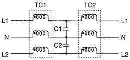
Therefore, in the present embodiment, the
図6に示すように濾波器15は、入力側及び出力側でのインピーダンスの低下を抑制するためのインピーダンスアッパにより構成されている。具体的には、濾波器15は、コンデンサC1,C2と、コイル群TC1,TC2とを備えている。コンデンサC1は、線路L1と線路Nとの間に並列接続されている。たコンデンサC2は、線路Nと線路L2との間に並列接続されている。
As shown in FIG. 6, the
コイル群TC1は、線路L1,N,L2のそれぞれにおいて、コンデンサC1,C2よりも幹線側に接続された3つのコイルを備えている。コイル群TC2は、線路L1,N,L2のそれぞれにおいて、コンデンサC1,C2よりも宅内側に接続された3つのコイルを備えている。 The coil group TC1 includes three coils connected to the main line side of the capacitors C1, C2 in each of the lines L1, N, L2. The coil group TC2 includes three coils connected to the inside of the house from the capacitors C1 and C2 in each of the lines L1, N, and L2.
ここで、コイル群TC1,TC2としては、幹線系通信部11及び宅内系通信部12の伝送帯域におけるインピーダンスが例えば10Ω以上の特性を有するものを採用することが好ましい。また、コンデンサC1,C2により濾波器15の遮断特性が決定される。
Here, as the coil groups TC1 and TC2, it is preferable to employ a coil having a characteristic that the impedance in the transmission band of the
なお、図6においては、単相3線式の構成を示したが、線路L1,L2から構成される2線式のものを採用してもよい。この場合、濾波器15は、線路L1と線路L2との間に接続されたコンデンサC1と、コンデンサC1よりも幹線側に接続されたコイル群TC1と、コンデンサC1よりも宅内側に接続されたコイル群TC2とにより構成すればよい。
In FIG. 6, a single-phase three-wire configuration is shown, but a two-wire configuration including lines L1 and L2 may be adopted. In this case, the
また、図5の電力量計10において、図4と同様、幹線系通信部11を低速伝送帯域の電力線搬送通信を行う通信モジュールにより構成し、宅内系通信部12を高速伝送帯域の電力線搬送通信を行う通信モジュールにより構成してもよい。
Further, in the watt-
集合住宅内での使用環境を考慮すれば、住戸数が多いことや一幹線当たりの住戸の密度も高いこと等により、隣接する住戸からのPLC信号の漏れが問題となる場合がある。その場合、図5の濾波器15として、宅内の伝送帯域(高速の電力線搬送通信:2〜30MHz)のみを遮断するものを採用することで、更に高効率な通信を実現することができる。
Considering the usage environment in the apartment house, leakage of PLC signals from adjacent dwelling units may be a problem due to the large number of dwelling units and the high density of dwelling units per trunk line. In that case, it is possible to realize more efficient communication by adopting the
(実施の形態5)
実施の形態5による電力線搬送通信システムは、実施の形態1〜4の構成において、宅内の電気機器40を集中制御する情報盤を更に設けたことを特徴とする。図7は、実施の形態5の電力線搬送通信システムの全体構成図である。電気機器40は、外部制御可能な例えばJEM−A端子を備える電気機器40から構成されている。
(Embodiment 5)
The power line carrier communication system according to the fifth embodiment is characterized in that, in the configuration of the first to fourth embodiments, an information panel for centrally controlling the
情報盤60は例えばJEM−Aの制御線を介して電気機器40と接続され、電気機器40を制御する。また、情報盤60は、電力線搬送通信モジュールにより構成される端末61を備え、宅内系電力線PL2を介して宅内分電盤20と接続されている。
The
なお、図7では、宅内分電盤20と情報盤60とは離れて配置されているが、図8に示すように隣接して配置してもよい。こうすることで、宅内分電盤20と情報盤60との伝送距離が短くなり、良好な電力線搬送通信を実現することができる。
In FIG. 7, the in-
また、図9に示すように、宅内分電盤20の主幹ブレーカ22の1次側(幹線側)に電力線搬送通信の通信モジュールから構成される端末21を設けてもよい。この場合、端末21は、電力線搬送通信により受信した信号を制御線を介して情報盤60に送信すればよい。これにより、主幹ブレーカ22がオフした状態でも、情報盤60は宅内分電盤20と通信することができ、電気機器40を制御することができる。
As shown in FIG. 9, a terminal 21 including a power line carrier communication module may be provided on the primary side (main line side) of the
更に、宅内系の電力線搬送通信として高速伝送帯域(2〜30MHz)の電力線搬送通信を採用することで、情報盤60は多量の情報を取り扱うことが可能となり、電気機器40をきめ細かく制御することが可能となる。また、宅内分電盤20に情報盤60を内蔵してもよい。
Furthermore, by adopting power line carrier communication in a high-speed transmission band (2 to 30 MHz) as in-home power line carrier communication, the
このように構成された電力線搬送通信システムは以下のように動作する。ここで、幹線系電力線PL1には、住戸の電力使用量を監視する外部サーバが接続されているものとする。情報盤60は、この外部サーバから、例えば電力使用量が過大であることを通知するためのPLC信号を宅内分電盤20を介して受信する。
The power line carrier communication system configured as described above operates as follows. Here, it is assumed that an external server for monitoring the power consumption of the dwelling unit is connected to the main power line PL1. The
そうすると、情報盤60は、電気機器40の電力使用量が低下するように電気機器40を制御する。この場合、情報盤60は、例えば、所定の電気機器40をオフしたり、エアコン等の電気機器40の設定温度を変更したりする。
Then, the
このように、実施の形態5による電力線搬送通信システムによれば、外部サーバからの通知に応じて、住戸の電力使用量を低下させることができる。 As described above, according to the power line carrier communication system according to the fifth embodiment, it is possible to reduce the power consumption of the dwelling unit according to the notification from the external server.
(実施の形態6)
実施の形態6による電力線搬送通信システムは、実施の形態5の構成において、情報盤60に公衆回線網との通信インターフェイス部を設けたことを特徴とする。図10は、実施の形態6による電力線搬送通信システムの全体構成図である。
(Embodiment 6)
The power line carrier communication system according to the sixth embodiment is characterized in that, in the configuration of the fifth embodiment, the
具体的には、通信インターフェイス部62(I/F)は、ADSLや光通信を行うための通信装置に対して、情報盤60を接続するための通信端子により構成されている。ここで、通信端子としては、イーサー端子、RS−232C端子、RS−486端子等を採用することができる。
Specifically, the communication interface unit 62 (I / F) includes a communication terminal for connecting the
情報盤60は、公衆回線網を介してサーバ70と接続されている。サーバ70は、電力量計10により計測された電力量情報を収集し、住戸の電力使用量を監視する。
The
ここで、情報盤60は、電力量計10から電力量情報を所定時刻あるいは、定期的に取得することが可能であり、取得した情報を公衆回線網を介してサーバ70に送信する。
Here, the
したがって、サーバ70は、公衆回線網を介して電力量情報を取得することができ、住戸の電力使用量を把握することができ、住戸における電力の使用制限をコントロールし、電力料金の時間帯割引サービスなどのアプリケーション面での拡充を図ることができる。
Therefore, the
このように構成された電力線搬送通信システムは、以下のように動作する。まず、電力量計10は、所定時刻になると電力量情報を宅内分電盤20を介して情報盤60に送信する。情報盤60は、受信した電力量情報を公衆回線網を介してサーバ70に送信する。
The power line carrier communication system configured as described above operates as follows. First, the
サーバ70は、住戸の電力使用量が過大であると判断すると、電力使用量が過大であることを通知するための信号を公衆網回線網を介して情報盤60に送信する。この信号を受信した情報盤60は、電気機器40を制御して、住戸における電力使用量を低下させる。この場合、情報盤60は、例えば、所定の電気機器40をオフしたり、エアコン等の電気機器40の設定温度を変更したりすればよい。
When the
このように、実施の形態6による電力線搬送通信システムによれば、サーバ70は、電力量計10により計測された電力量情報を収集することができる。
Thus, according to the power line carrier communication system according to the sixth embodiment, the
(実施の形態7)
実施の形態7による電力線搬送通信システムは、実施の形態6の構成において、宅内分電盤20に電力量計を設けたことを特徴とする。なお、本実施の形態において、実施の形態1〜6と同一のものは説明を省く。
(Embodiment 7)
The power line carrier communication system according to the seventh embodiment is characterized in that, in the configuration of the sixth embodiment, a watt-hour meter is provided in the
図10に示すように、宅内分電盤20は、電力量計23を備えている。電力量計23は、電力量計10に比べて、測定精度が低い安価な電力量計により構成されている。
As shown in FIG. 10, the
電力量計10は法規上の型式を採った高精度な電力量計であるため、情報盤60は電力量計10による電力量情報の自由な取得が制限される場合もある。この場合、情報盤60は、電力量計23により計測された電力量情報を取得して、サーバ70に送信する。一方、情報盤60は、電力量計10から電力量情報を取得することができた場合、こちらの電力量情報の方が信頼性が高いため、情報盤60は、電力量計23により計測された電力量情報ではなく、電力量計10により計測された電力量情報をサーバ70に送信する。
Since the watt-
また、本実施の形態では、宅内分電盤20は、モニタ部及びスピーカを備えている。そして、宅内の電力使用量が急激に変化した場合、宅内分電盤20は、モニタ部及びスピーカを用いて電力使用量が使いすぎであることをユーザに報知する。
Moreover, in this Embodiment, the
また、夏場、冬場など電力需要が高い時期において、電力使用量が制限される場合、宅内分電盤20は、ユーザにモニタ部及びスピーカを用いて電力使用量を控える旨の報知を行う。
In addition, when the power usage is restricted in a period when the power demand is high, such as summer and winter, the in-
また、宅内分電盤20は、住戸における毎月の電力使用量の目標値を設定し、モニタ部及びスピーカを用いて、設定した目標値をユーザに報知する。
Moreover, the
このように、実施の形態7による電力線搬送通信システムによれば、宅内分電盤20が電力量計23を備えているため、電力量計10による電力量情報の取得が制限されている場合であっても、住戸の電力使用量を把握することができる。
As described above, according to the power line carrier communication system according to the seventh embodiment, since the
10 電力量計
11 幹線系通信部
12 宅内系通信部
13 電力量計器部
14 通信部
15 濾波器
20 宅内分電盤
30 コンセント
40 電気機器
50 端末
PL1 幹線系電力線
PL2 宅内系電力線
DESCRIPTION OF
Claims (9)
前記幹線系電力線に接続された電力量計と、
前記電力量計に接続され、前記幹線系電力線を介して供給される商用電力を、宅内分電盤の配下に接続された電気機器に供給する宅内系電力線とを備え、
前記電力量計は、
前記幹線系電力線を介して電力線搬送通信を行う第1の通信部と、
前記宅内系電力線を介して電力線搬送通信を行う第2の通信部とを備えることを特徴とする電力線搬送通信システム。 A trunk power line that supplies commercial power stepped down by a transformer to the house;
A watt-hour meter connected to the trunk power line;
A commercial power line connected to the watt-hour meter and supplied via the trunk power line, to a home power line connected to an electrical device connected to a subordinate of a residential distribution board,
The electricity meter
A first communication unit that performs power line carrier communication via the trunk power line;
A power line carrier communication system comprising: a second communication unit that performs power line carrier communication via the in-home power line.
前記第2の通信部は、前記宅内系電力線からの通信信号を前記幹線系電力線に中継することを特徴とする請求項1記載の電力線搬送通信システム。 The first communication unit relays a communication signal from the trunk power line to the home power line,
2. The power line carrier communication system according to claim 1, wherein the second communication unit relays a communication signal from the in-home power line to the main power line.
前記第2の通信部は、前記低速伝送帯域よりも高い所定の高速伝送帯域で電力線搬送通信を行うことを特徴とする請求項1又は2記載の電力線搬送通信システム。 The first communication unit performs power line carrier communication in a predetermined low-speed transmission band,
The power line carrier communication system according to claim 1 or 2, wherein the second communication unit performs power line carrier communication in a predetermined high speed transmission band higher than the low speed transmission band.
Priority Applications (1)
| Application Number | Priority Date | Filing Date | Title |
|---|---|---|---|
| JP2008162267A JP5415026B2 (en) | 2008-06-20 | 2008-06-20 | Electricity meter and power line carrier communication system |
Applications Claiming Priority (1)
| Application Number | Priority Date | Filing Date | Title |
|---|---|---|---|
| JP2008162267A JP5415026B2 (en) | 2008-06-20 | 2008-06-20 | Electricity meter and power line carrier communication system |
Related Child Applications (3)
| Application Number | Title | Priority Date | Filing Date |
|---|---|---|---|
| JP2013234045A Division JP5816846B2 (en) | 2013-11-12 | 2013-11-12 | Distribution board and distribution board system |
| JP2013234047A Division JP5861126B2 (en) | 2013-11-12 | 2013-11-12 | Electricity meter |
| JP2013234046A Division JP5861125B2 (en) | 2013-11-12 | 2013-11-12 | Energy meter and communication module |
Publications (2)
| Publication Number | Publication Date |
|---|---|
| JP2010004389A true JP2010004389A (en) | 2010-01-07 |
| JP5415026B2 JP5415026B2 (en) | 2014-02-12 |
Family
ID=41585693
Family Applications (1)
| Application Number | Title | Priority Date | Filing Date |
|---|---|---|---|
| JP2008162267A Expired - Fee Related JP5415026B2 (en) | 2008-06-20 | 2008-06-20 | Electricity meter and power line carrier communication system |
Country Status (1)
| Country | Link |
|---|---|
| JP (1) | JP5415026B2 (en) |
Cited By (21)
| Publication number | Priority date | Publication date | Assignee | Title |
|---|---|---|---|---|
| CN102306930A (en) * | 2011-09-14 | 2012-01-04 | 渭南供电局 | Trip system of total residual current operated protector of distribution area and application method thereof |
| JP3179034U (en) * | 2012-08-01 | 2012-10-11 | 有限会社あかつきプランニング | Automatic power distribution management system |
| JP2013055819A (en) * | 2011-09-05 | 2013-03-21 | Sumitomo Electric Ind Ltd | Power generation control system and power conditioner |
| WO2013073548A1 (en) * | 2011-11-16 | 2013-05-23 | パナソニック株式会社 | Wireless communication apparatus, wireless communication system having same, and power consumption management apparatus |
| CN103607218A (en) * | 2013-10-28 | 2014-02-26 | 国家电网公司 | Cross-frequency-band power-line carrier communication system and communication method thereof |
| JP2014078841A (en) * | 2012-10-10 | 2014-05-01 | Toyo Networks & System Integration Co Ltd | Power line communication system and watt-hour meter used for this |
| WO2014125812A1 (en) * | 2013-02-13 | 2014-08-21 | パナソニック株式会社 | Terminal apparatus, measurement apparatus, and communication system |
| JP2014158135A (en) * | 2013-02-15 | 2014-08-28 | Tokyo Electric Power Co Inc:The | Energy management system |
| JP2014200141A (en) * | 2013-03-29 | 2014-10-23 | パナソニック株式会社 | Measuring device |
| JP2014202542A (en) * | 2013-04-02 | 2014-10-27 | パナソニック株式会社 | Measurement device |
| CN104137430A (en) * | 2012-03-01 | 2014-11-05 | 松下电器产业株式会社 | Child node device for power management system and power management system |
| JP2015033013A (en) * | 2013-08-02 | 2015-02-16 | ネッツエスアイ東洋株式会社 | Power line communication system and watt-hour meter used for the same |
| JP2015032947A (en) * | 2013-08-01 | 2015-02-16 | ネッツエスアイ東洋株式会社 | Automatic meter reading system |
| JP2015032946A (en) * | 2013-08-01 | 2015-02-16 | ネッツエスアイ東洋株式会社 | Automatic meter reading system |
| JP2015050621A (en) * | 2013-09-02 | 2015-03-16 | ネッツエスアイ東洋株式会社 | Automatic meter reading system |
| JP2015050620A (en) * | 2013-09-02 | 2015-03-16 | ネッツエスアイ東洋株式会社 | Automatic meter reading system |
| JP2015070693A (en) * | 2013-09-27 | 2015-04-13 | パナソニック株式会社 | Communication apparatus and distribution board including the same |
| JP2015070441A (en) * | 2013-09-27 | 2015-04-13 | パナソニック株式会社 | Communication apparatus, circuit breaker including the same and distribution board |
| JP2015091000A (en) * | 2013-11-05 | 2015-05-11 | パナソニックIpマネジメント株式会社 | Distribution board |
| WO2015104740A1 (en) * | 2014-01-10 | 2015-07-16 | パナソニックIpマネジメント株式会社 | Control system and distribution board |
| CN113114303A (en) * | 2021-03-19 | 2021-07-13 | 江苏固德威电源科技股份有限公司 | Anti-interference method of photovoltaic power carrier data collector in double-split transformer |
Families Citing this family (1)
| Publication number | Priority date | Publication date | Assignee | Title |
|---|---|---|---|---|
| CN104092481B (en) * | 2014-07-17 | 2016-04-20 | 江苏林洋能源股份有限公司 | A kind of by voltage characteristic differentiation Tai Qu and phase method for distinguishing |
Citations (6)
| Publication number | Priority date | Publication date | Assignee | Title |
|---|---|---|---|---|
| JP2002233082A (en) * | 2001-02-01 | 2002-08-16 | Nec Access Technica Ltd | Power line carrying control system and control equipment |
| JP2003021654A (en) * | 2001-07-05 | 2003-01-24 | Nec Yonezawa Ltd | Power consumption management system for electric machinery and apparatus |
| JP2003069728A (en) * | 2001-08-24 | 2003-03-07 | Hitachi Ltd | Communication method, bidirectional television receiver, power line carrier and blocking filter |
| JP2004015165A (en) * | 2002-06-04 | 2004-01-15 | Hitachi Ltd | Repeater for power line carrier, optical/power line carrier apparatus for power line carrier, and power line carrier system |
| JP2006033082A (en) * | 2004-07-12 | 2006-02-02 | Sumitomo Electric Ind Ltd | Signal distributor |
| JP2006140580A (en) * | 2004-11-10 | 2006-06-01 | Ricoh Co Ltd | Power line transport communication system, power line transport communication method, and distribution board |
-
2008
- 2008-06-20 JP JP2008162267A patent/JP5415026B2/en not_active Expired - Fee Related
Patent Citations (6)
| Publication number | Priority date | Publication date | Assignee | Title |
|---|---|---|---|---|
| JP2002233082A (en) * | 2001-02-01 | 2002-08-16 | Nec Access Technica Ltd | Power line carrying control system and control equipment |
| JP2003021654A (en) * | 2001-07-05 | 2003-01-24 | Nec Yonezawa Ltd | Power consumption management system for electric machinery and apparatus |
| JP2003069728A (en) * | 2001-08-24 | 2003-03-07 | Hitachi Ltd | Communication method, bidirectional television receiver, power line carrier and blocking filter |
| JP2004015165A (en) * | 2002-06-04 | 2004-01-15 | Hitachi Ltd | Repeater for power line carrier, optical/power line carrier apparatus for power line carrier, and power line carrier system |
| JP2006033082A (en) * | 2004-07-12 | 2006-02-02 | Sumitomo Electric Ind Ltd | Signal distributor |
| JP2006140580A (en) * | 2004-11-10 | 2006-06-01 | Ricoh Co Ltd | Power line transport communication system, power line transport communication method, and distribution board |
Cited By (28)
| Publication number | Priority date | Publication date | Assignee | Title |
|---|---|---|---|---|
| JP2013055819A (en) * | 2011-09-05 | 2013-03-21 | Sumitomo Electric Ind Ltd | Power generation control system and power conditioner |
| CN102306930A (en) * | 2011-09-14 | 2012-01-04 | 渭南供电局 | Trip system of total residual current operated protector of distribution area and application method thereof |
| CN103947122A (en) * | 2011-11-16 | 2014-07-23 | 松下电器产业株式会社 | Wireless communication apparatus, wireless communication system having same, and power consumption management apparatus |
| WO2013073548A1 (en) * | 2011-11-16 | 2013-05-23 | パナソニック株式会社 | Wireless communication apparatus, wireless communication system having same, and power consumption management apparatus |
| JP2013106322A (en) * | 2011-11-16 | 2013-05-30 | Panasonic Corp | Radio communication device and radio communication system including the same |
| TWI467880B (en) * | 2011-11-16 | 2015-01-01 | Panasonic Corp | Wireless communication device, wireless communication system with the same, and power measurement device |
| CN104137430A (en) * | 2012-03-01 | 2014-11-05 | 松下电器产业株式会社 | Child node device for power management system and power management system |
| JP3179034U (en) * | 2012-08-01 | 2012-10-11 | 有限会社あかつきプランニング | Automatic power distribution management system |
| JP2014078841A (en) * | 2012-10-10 | 2014-05-01 | Toyo Networks & System Integration Co Ltd | Power line communication system and watt-hour meter used for this |
| WO2014125812A1 (en) * | 2013-02-13 | 2014-08-21 | パナソニック株式会社 | Terminal apparatus, measurement apparatus, and communication system |
| JP2014158135A (en) * | 2013-02-15 | 2014-08-28 | Tokyo Electric Power Co Inc:The | Energy management system |
| JP2016001909A (en) * | 2013-02-15 | 2016-01-07 | 東京電力株式会社 | Energy management system |
| JP2014200141A (en) * | 2013-03-29 | 2014-10-23 | パナソニック株式会社 | Measuring device |
| JP2014202542A (en) * | 2013-04-02 | 2014-10-27 | パナソニック株式会社 | Measurement device |
| JP2015032946A (en) * | 2013-08-01 | 2015-02-16 | ネッツエスアイ東洋株式会社 | Automatic meter reading system |
| JP2015032947A (en) * | 2013-08-01 | 2015-02-16 | ネッツエスアイ東洋株式会社 | Automatic meter reading system |
| JP2015033013A (en) * | 2013-08-02 | 2015-02-16 | ネッツエスアイ東洋株式会社 | Power line communication system and watt-hour meter used for the same |
| JP2015050621A (en) * | 2013-09-02 | 2015-03-16 | ネッツエスアイ東洋株式会社 | Automatic meter reading system |
| JP2015050620A (en) * | 2013-09-02 | 2015-03-16 | ネッツエスアイ東洋株式会社 | Automatic meter reading system |
| JP2015070693A (en) * | 2013-09-27 | 2015-04-13 | パナソニック株式会社 | Communication apparatus and distribution board including the same |
| JP2015070441A (en) * | 2013-09-27 | 2015-04-13 | パナソニック株式会社 | Communication apparatus, circuit breaker including the same and distribution board |
| CN103607218A (en) * | 2013-10-28 | 2014-02-26 | 国家电网公司 | Cross-frequency-band power-line carrier communication system and communication method thereof |
| CN103607218B (en) * | 2013-10-28 | 2016-04-20 | 国家电网公司 | A kind of across frequency band power-line carrier communication system and communication means thereof |
| JP2015091000A (en) * | 2013-11-05 | 2015-05-11 | パナソニックIpマネジメント株式会社 | Distribution board |
| WO2015068358A1 (en) * | 2013-11-05 | 2015-05-14 | パナソニックIpマネジメント株式会社 | Distribution switchboard |
| WO2015104740A1 (en) * | 2014-01-10 | 2015-07-16 | パナソニックIpマネジメント株式会社 | Control system and distribution board |
| JPWO2015104740A1 (en) * | 2014-01-10 | 2017-03-23 | パナソニックIpマネジメント株式会社 | Control system and distribution board |
| CN113114303A (en) * | 2021-03-19 | 2021-07-13 | 江苏固德威电源科技股份有限公司 | Anti-interference method of photovoltaic power carrier data collector in double-split transformer |
Also Published As
| Publication number | Publication date |
|---|---|
| JP5415026B2 (en) | 2014-02-12 |
Similar Documents
| Publication | Publication Date | Title |
|---|---|---|
| JP5415026B2 (en) | Electricity meter and power line carrier communication system | |
| US9344150B2 (en) | Powerline modem device | |
| RU2463705C2 (en) | System for communication via distribution transmission lines | |
| JP2012205078A (en) | Monitoring system for photovoltaic power generation | |
| WO2011039585A1 (en) | Electric power management system | |
| JP2015012447A (en) | Communication system and communication device | |
| CN102597789A (en) | Electric power meter | |
| JP5861126B2 (en) | Electricity meter | |
| JP5861125B2 (en) | Energy meter and communication module | |
| JP2009063360A (en) | Energy consumption per unit monitoring system using plc communication | |
| EP2437074A2 (en) | Powerline modem device | |
| Hsieh et al. | Broadcasting control of intelligent air conditioners using power line carrier technology | |
| JP5816846B2 (en) | Distribution board and distribution board system | |
| JP6039022B2 (en) | Energy management system | |
| KR101711235B1 (en) | Device for use in a power line communication system and power line communication systems | |
| CN108112273A (en) | Voltameter and the adaptor module for it | |
| EP2499503B1 (en) | Current measuring apparatus | |
| JP6159612B2 (en) | Power line communication system and watt-hour meter used therefor | |
| JP2016220143A (en) | Remote meter reading system | |
| JP2007158848A (en) | Power line carrier communication system | |
| JP6060410B2 (en) | Power line communication system and watt-hour meter used therefor | |
| JP2004236056A (en) | Power line carrier communication system | |
| JP2015091001A (en) | Distribution board | |
| JP6492256B2 (en) | Power line communication system and watt-hour meter used therefor | |
| Annadate et al. | Industrial automation system using power line communication and Android device |
Legal Events
| Date | Code | Title | Description |
|---|---|---|---|
| A621 | Written request for application examination |
Free format text: JAPANESE INTERMEDIATE CODE: A621 Effective date: 20110323 |
|
| A711 | Notification of change in applicant |
Free format text: JAPANESE INTERMEDIATE CODE: A712 Effective date: 20120111 |
|
| A977 | Report on retrieval |
Free format text: JAPANESE INTERMEDIATE CODE: A971007 Effective date: 20120803 |
|
| A131 | Notification of reasons for refusal |
Free format text: JAPANESE INTERMEDIATE CODE: A131 Effective date: 20120807 |
|
| A521 | Written amendment |
Free format text: JAPANESE INTERMEDIATE CODE: A523 Effective date: 20120924 |
|
| A131 | Notification of reasons for refusal |
Free format text: JAPANESE INTERMEDIATE CODE: A131 Effective date: 20130326 |
|
| A521 | Written amendment |
Free format text: JAPANESE INTERMEDIATE CODE: A523 Effective date: 20130513 |
|
| TRDD | Decision of grant or rejection written | ||
| A01 | Written decision to grant a patent or to grant a registration (utility model) |
Free format text: JAPANESE INTERMEDIATE CODE: A01 Effective date: 20131015 |
|
| A61 | First payment of annual fees (during grant procedure) |
Free format text: JAPANESE INTERMEDIATE CODE: A61 Effective date: 20131113 |
|
| R150 | Certificate of patent or registration of utility model |
Ref document number: 5415026 Country of ref document: JP Free format text: JAPANESE INTERMEDIATE CODE: R150 |
|
| LAPS | Cancellation because of no payment of annual fees |