JP2010004068A - Terminal box and solar-battery module - Google Patents
Terminal box and solar-battery module Download PDFInfo
- Publication number
- JP2010004068A JP2010004068A JP2009219624A JP2009219624A JP2010004068A JP 2010004068 A JP2010004068 A JP 2010004068A JP 2009219624 A JP2009219624 A JP 2009219624A JP 2009219624 A JP2009219624 A JP 2009219624A JP 2010004068 A JP2010004068 A JP 2010004068A
- Authority
- JP
- Japan
- Prior art keywords
- terminal
- terminal block
- box
- lead wire
- output lead
- Prior art date
- Legal status (The legal status is an assumption and is not a legal conclusion. Google has not performed a legal analysis and makes no representation as to the accuracy of the status listed.)
- Granted
Links
Images


Classifications
-
- Y—GENERAL TAGGING OF NEW TECHNOLOGICAL DEVELOPMENTS; GENERAL TAGGING OF CROSS-SECTIONAL TECHNOLOGIES SPANNING OVER SEVERAL SECTIONS OF THE IPC; TECHNICAL SUBJECTS COVERED BY FORMER USPC CROSS-REFERENCE ART COLLECTIONS [XRACs] AND DIGESTS
- Y02—TECHNOLOGIES OR APPLICATIONS FOR MITIGATION OR ADAPTATION AGAINST CLIMATE CHANGE
- Y02E—REDUCTION OF GREENHOUSE GAS [GHG] EMISSIONS, RELATED TO ENERGY GENERATION, TRANSMISSION OR DISTRIBUTION
- Y02E10/00—Energy generation through renewable energy sources
- Y02E10/50—Photovoltaic [PV] energy
Abstract
Description
本発明は、太陽電池セルの電極に接続されバックフィルムを貫通して引き出された出力リード線を電気的に接続する端子ボックスに係り、より詳細には、出力リード線の配線構造に特徴を有する端子ボックス及びこの端子ボックスを備えた太陽電池モジュールに関する。 The present invention relates to a terminal box that is electrically connected to an output lead wire that is connected to an electrode of a solar battery cell and pulled out through a back film, and more specifically, has a feature in the wiring structure of the output lead wire. The present invention relates to a terminal box and a solar cell module including the terminal box.
建物の屋根等に複数枚の太陽電池ストリングをマトリックス状に敷設して太陽光発電を行う太陽光発電システムが広く一般に普及しはじめている。このような太陽電池発電システムにおいて、各太陽電池モジュールには、隣接して敷設された他の太陽電池モジュールと互いに電気的に接続可能とするための端子ボックスが備えられている。 2. Description of the Related Art Photovoltaic power generation systems that perform solar power generation by laying a plurality of solar cell strings in a matrix on the roof of a building and the like have begun to be widely spread. In such a solar cell power generation system, each solar cell module is provided with a terminal box that can be electrically connected to other solar cell modules installed adjacent to each other.
従来の端子ボックスの一例を、従来技術1として図5に示す。ただし、図5(a)は断面図、(b)は平面図である。 An example of a conventional terminal box is shown in FIG. 5A is a sectional view, and FIG. 5B is a plan view.
この従来技術1の端子ボックス200は、太陽電池ストリング300のバックフィルム310を貫通して引き出された出力リード線301を電気的に接続するために、太陽電池ストリング300の裏面上に載置固定されるボックスケース201と、このボックスケース201上に形成された端子台210とからなっている。また、ボックスケース201は、太陽電池ストリング300の裏面上に載置固定されるケース本体202と、このケース本体202の上部に前記端子台210を載置固定するための端子台固定部203とからなっている。
The
そして、ケース本体202には、太陽電池ストリング300の裏面から引き出された出力リード線301を上方に引き出すための本体挿通穴204が形成されている。また、この本体挿通穴204と対向する側の端子台210の一端部211は、端子固定部203から突出するように設けられており、この突出部に、出力リード線301の先端部302を挿通するための端子台挿通穴212が形成されている。
The case
このような構成の端子ボックス200を用いて出力リード線301を電気的に接続する場合、まず、太陽電池ストリング300の裏面を上に向けて図示しない作業台の上に載置し、この太陽電池ストリング300の裏面から上方に引き出された出力リード線301の先端部302に、端子ボックスの本体挿通穴204が対向するように位置合わせして、端子ボックス200を太陽電池ストリング300の上方から被せるように載置する。次に、この状態で本体挿通穴204から上方に突出した出力リード線301をピンセット等で摘んで端子台210の方に折り曲げ、出力リード線301の先端部302を端子台210に形成された端子台挿通穴212に上方から挿通する。そして、この状態で端子台210上の出力リード線301を半田付けによって端子台210に固定することで、出力リード線301を端子台210に取り付け固定するようになっている。
When the
このように、出力リード線301の先端部302を、単なる半田固定ではなく、端子台挿通穴212に一旦挿通(係止)してから半田固定するのは、IEC(International Electrotechnical Commission)規格によってそのように規定(半田固定だけではだめであ
ると規定)されているからである。
As described above, the
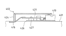
また、従来の端子ボックスの他の例として、特許文献1に記載の端子ボックス(接続ボックス)の構造を図6に示す。
Moreover, the structure of the terminal box (connection box) of
この特許文献1に記載の端子ボックス402は、ボックス体424のケーブル嵌通孔410から挿入されて端子固定部427に抜止係止された端子421の長手方向他端部に、フレーム挿入孔426から挿入されたリードフレーム416の先端部が半田付けにより接続され、端子ボックス402のボックス本体424の下面が太陽電池ストリング本体401の裏面に接着剤により接着固定された構造となっている。
The
一方、上記従来技術1の端子ボックス100では、出力リード線201と端子台110との固定を半田付けによる固定としているが、このような半田付けの工程を無くすようにした端子ボックスも提案されている(例えば、特許文献2参照)。
On the other hand, in the terminal box 100 of
特許文献2に記載の端子ボックスは、図7に示すように、太陽電池ストリング507の電極取り出し部506を覆うように取り付けられており、端子ボックス501の底面には内部リード線503を取り込むための内部リード線取り込み孔508が形成されている。また、端子ボックス501内には、内部リード線取り込み孔508の近傍に中継端子504を機械的に固定するための中継端子支持体505が形成されている。そして、内部リード線503と外部出力線502が中継端子504により互いに電気的かつ機械的に接続され、この中継端子504に穿設された掛止部(開口部)513を棒状の中継端子支持体505に通すことにより、中継端子504を中継端子支持体505に機械的に固定する構造となっている。
As shown in FIG. 7, the terminal box described in Patent Document 2 is attached so as to cover the
上記従来技術1の端子ボックスでは、本体挿通穴204から上方に突出した出力リード線301の先端部302を端子台210に形成された端子台挿通穴212に上方から挿通するという工程が必要であるため、自動化が難しいといった問題があった。
In the terminal box of Prior
また、出力リード線301を取り出すための本体挿通穴204と、取り出された出力リード線301の先端部302を挿通するための端子台210の端子台挿通穴212とを個別に設けており、本体挿通穴204から取り出された出力リード線301を湾曲させて端子台挿通穴212に挿通させるため、本体挿通穴204から端子台挿通穴212まである程度の距離が必要であり、この部分のスペースが無駄であるといった問題があった。すなわち、端子ボックスの小型化が難しいといった問題があった。この問題は、上記特許文献1や特許文献2に記載の端子ボックスについても同様に生じる問題である。
Further, a main
また、本体挿通穴204から端子台挿通穴212まである程度の距離があるため、出力リード線301も本体挿通穴204から上方に十分長く引き出す必要がある。そのため、引き出された出力リード線301がぐらつくことで、出力リード線301の端子台210への半田付けが安定して行われない可能性があるといった問題があった。この問題は、上記特許文献1に記載の端子ボックスについても同様に生じる問題である。
Further, since there is a certain distance from the main
さらに、端子ボックス200を太陽電池ストリング300の上方から被せるとき、端子ボックス200の本体挿通穴204の縁部が出力リード線301に接触して折れ曲がらないように、本体挿通穴204の内径を十分大きくしておく必要がある。すなわち、本体挿通穴204を大きな開口部に形成しておく必要がある。そのため、出力リード線301の先端部302を端子台210の端子台挿通穴212に上方から挿通するとき、出力リード線301を深く挿通すると、出力リード線301の先端部302が端子台固定部203の側面203aやケース本体202の上面202aなどに接触してC字状に湾曲し、本体挿
通穴204から太陽電池ストリング300の裏面まで入り込む可能性があり、この場合には絶縁耐圧が低くなってしまうといった問題があった。
Furthermore, when covering the
なお、上記特許文献1に記載の端子ボックスについては、リードフレーム416を端子421に単に半田付けするだけであるため、固定強度が十分でなく、また、IEC規格にも準拠していないといった問題もあった。同様に、特許文献2に記載の端子ボックスについても、内部リード線503と外部出力線502とが中継端子504に半田付けのみによって固定されているため、この部分の強度が十分でなく、また、IEC規格にも準拠していないといった問題があった。
Note that the terminal box described in
本発明はかかる問題点を解決すべく創案されたもので、その目的は、特に上記従来技術1の端子ボックスに着目し、これを改良することで上記各問題を解決した端子ボックス及びこの端子ボックスを備えた太陽電池モジュールを提供することにある。
The present invention was devised to solve such problems, and its purpose is to focus particularly on the terminal box of the
上記課題を解決するため、本発明の端子ボックスは、太陽電池セルの電極に接続されバックフィルムを貫通して引き出された出力リード線を電気的に接続する端子ボックスであって、前記バックフィルム上に載置固定されるボックスケースと、このボックスケース上に形成された前記出力リード線を電気的に接続する端子台とからなり、前記ボックスケースはさらに、前記バックフィルム上に載置固定されるケース本体と、このケース本体の上部に前記端子台を載置固定するための端子台固定部とからなり、前記出力リード線を前記端子台の上方まで通すための開口部が前記ケース本体の底面から前記端子台の上面まで一連に形成されていることを特徴としている。 In order to solve the above problems, a terminal box of the present invention is a terminal box that is connected to an electrode of a solar battery cell and electrically connects an output lead wire that is drawn through a back film, and is on the back film. And a terminal block for electrically connecting the output lead wire formed on the box case, and the box case is further mounted and fixed on the back film. The case main body includes a terminal block fixing portion for mounting and fixing the terminal block on the upper portion of the case main body, and an opening for passing the output lead wire to above the terminal block is a bottom surface of the case main body. To the upper surface of the terminal block.
また、本発明の太陽電池モジュールは、太陽電池セルの電極に接続されバックフィルムを貫通して引き出された出力リード線を電気的に接続する端子ボックスを備えた太陽電池モジュールであって、前記端子ボックスは、前記バックフィルム上に載置固定されるボックスケースと、このボックスケース上に形成された前記出力リード線を電気的に接続する端子台とからなり、前記ボックスケースはさらに、前記バックフィルム上に載置固定されるケース本体と、このケース本体の上部に前記端子台を載置固定するための端子台固定部とからなり、前記出力リード線を前記端子台の上方まで通すための開口部が前記ケース本体の底面から前記端子台の上面まで一連に形成されていることを特徴としている。 Further, the solar cell module of the present invention is a solar cell module including a terminal box that is connected to the electrode of the solar cell and electrically connects the output lead wire drawn through the back film, the terminal The box includes a box case that is placed and fixed on the back film, and a terminal block that electrically connects the output lead wires formed on the box case. The box case further includes the back film. An opening for passing the output lead wire up to the upper side of the terminal block, comprising a case main body mounted and fixed on the terminal block, and a terminal block fixing portion for mounting and fixing the terminal block on the upper portion of the case main body. The portion is formed in a series from the bottom surface of the case body to the top surface of the terminal block.
上記構成によれば、出力リード線を端子台の上方まで通すための開口部が、ケース本体の底面から端子台の上面まで一連に形成されている。すなわち、開口部は一つだけであり、従来技術1のように、本体挿通穴104と端子台挿通穴112とが個別に設けられた構成ではないので、従来技術1の端子ボックスのような無駄なスペースを無くすことができ、端子ボックス自体を小型化することが可能である。
According to the said structure, the opening part for letting an output lead wire pass to the upper direction of a terminal block is formed in a row from the bottom face of a case main body to the upper surface of a terminal block. That is, there is only one opening, and unlike the
また、本発明によれば、前記ケース本体に形成された前記開口部は、前記端子台固定部に連通する側から前記ケース本体の底面に向かって漸次拡開するテーパ状の貫通穴に形成されていることが好ましい。このようにテーパ状に形成することで、出力リード線を挿通する開口部の下端部の口径が大きくなることから、出力リード線が開口部の縁部に当たって折れ曲がってしまうといった不具合を防止することができる。 According to the present invention, the opening formed in the case body is formed in a tapered through hole that gradually expands from the side communicating with the terminal block fixing portion toward the bottom surface of the case body. It is preferable. By forming the tapered shape in this way, the diameter of the lower end portion of the opening through which the output lead wire is inserted becomes large, so that the problem that the output lead wire hits the edge of the opening and is bent can be prevented. it can.
また、本発明によれば、前記端子台の一方の縁部が、前記出力リード線の先端部を折り曲げ係止可能なように前記端子台固定部から突出して設けられた構成としてもよい。すなわち、本発明では、開口部から上方に突出した出力リード線をそのまま開口部の縁部に押し当てるようにして端子台の一方の縁部側に折り曲げ、その折り曲げ先端部をさら端子台の一方の縁部に押し当てるようにして、下方に折り返すまで折り曲げることにより、出力
リード線の先端部を端子台に係止固定することが可能となる。すなわち、端子台の開口部の縁部、及び端子台の一方の縁部の2点をそれぞれ折り曲げ起点として、2回の折り曲げ工程を実施するだけで、出力リード線の先端部を端子台に確実に係止固定することが可能となる。これにより、出力リード線の先端部を端子台に半田付けする次の工程も安定して行うことが可能となり、IEC規格に十分準拠した端子ボックスの取り付け構造とすることができる。
Moreover, according to this invention, it is good also as a structure which the one edge part of the said terminal block protruded from the said terminal block fixing part so that the front-end | tip part of the said output lead wire can be bent and latched. That is, according to the present invention, the output lead wire protruding upward from the opening is pressed against the edge of the opening as it is and bent to one edge side of the terminal block, and the bent tip is one side of the terminal block. It is possible to lock and fix the tip end of the output lead wire to the terminal block by bending it until it is folded back downward. In other words, the tip of the output lead wire is securely attached to the terminal block only by performing the bending process twice with the two edges of the opening of the terminal block and one edge of the terminal block as the starting points. It becomes possible to lock and fix to. As a result, the next step of soldering the tip of the output lead wire to the terminal block can be stably performed, and a terminal box mounting structure sufficiently compliant with the IEC standard can be obtained.
また、本発明によれば、前記端子台固定部は、前記ケース本体の前後方向に所定の間隔を存して立設された一対の端子台固定片によって形成され、この端子台固定片の間を前記出力リード線を通すための開口部としてもよい。すなわち、端子台固定部に形成される開口部は、円筒形のようないわゆる穴ではなく、左右両側が開放された溝のような構造となっている。そのため、この端子ボックスに出力リード線及び外部出力線を接続した後、ポッティングによって樹脂封止するとき、ポッティング材が開口部から内部に流入し易くなり、バックフィルムを貫通して引き出された出力リード線の周辺を確実に樹脂封止することが可能となる。この場合、前記ケース本体に、当該ケース本体の底面から上面まで達する空気抜き孔が設けた構成としてもよい。空気抜き孔を設けることで、ポッティング材が開口部に流れ込むとき、開口部内及び太陽電池セルの裏面と端子ボックスの底面との隙間に存在している空気が、空気抜き孔から外部に抜けるため、ポッティング材を開口部内(より具体的には、開口部内の太陽電池セルのバックフィルムまで、さらには太陽電池セルのバックフィルムと端子ボックスの底面との隙間まで)確実に充填することができ、空隙の無い樹脂封止を行うことが可能となる。 Further, according to the present invention, the terminal block fixing portion is formed by a pair of terminal block fixing pieces erected at a predetermined interval in the front-rear direction of the case body, and between the terminal block fixing pieces. It is good also as an opening part for letting the said output lead wire pass. That is, the opening formed in the terminal block fixing portion is not a so-called hole having a cylindrical shape, but has a structure like a groove having both left and right sides opened. Therefore, after connecting the output lead wire and external output wire to this terminal box, when the resin is sealed by potting, the potting material tends to flow into the inside from the opening, and the output lead pulled out through the back film It becomes possible to securely seal the periphery of the wire with resin. In this case, the case body may have a configuration in which an air vent hole extending from the bottom surface to the top surface of the case body is provided. By providing an air vent hole, when the potting material flows into the opening, the air present in the opening and in the gap between the back surface of the solar battery cell and the bottom surface of the terminal box escapes to the outside from the air vent hole. Can be reliably filled in the opening (more specifically, to the back film of the solar cell in the opening, and further to the gap between the back film of the solar cell and the bottom of the terminal box), and there is no void. Resin sealing can be performed.
本発明によれば、出力リード線を端子台の上方まで通すための開口部が、ケース本体の底面から端子台の上面まで一連に形成されているので、従来技術のように2つの挿通孔を個別に設ける必要がなく、従って、従来技術の端子ボックスのような無駄なスペースを無くして、端子ボックス自体を小型化することができる。 According to the present invention, since the openings for passing the output lead wires up to the upper side of the terminal block are formed in series from the bottom surface of the case body to the upper surface of the terminal block, two insertion holes are provided as in the prior art. There is no need to provide them separately. Therefore, it is possible to reduce the size of the terminal box itself without using a wasted space like the terminal box of the prior art.
以下、本発明の実施の形態について、図面を参照して説明する。 Embodiments of the present invention will be described below with reference to the drawings.
<太陽電池ストリングの説明>
まず、最初に、本発明の端子ボックスが適用される太陽電池ストリングの一構成例について、図3(a),(b)及び図4を参照して説明する。
<Description of solar cell string>
First, one structural example of the solar cell string to which the terminal box of the present invention is applied will be described with reference to FIGS. 3 (a), 3 (b) and FIG.
太陽電池セル115は、透光性絶縁基板111上に、図示は省略しているが透明導電膜からなる透明電極膜、光電変換層、裏面電極膜がこの順に積層されて形成されている。透光性絶縁基板としてはガラスやポリイミドなどの耐熱性樹脂がある。透明電極膜としてはSnO2 、ZnO、ITOなどがある。光電変換層としてはアモルファスシリコンがある。
Although not shown, the
このように構成された太陽電池セル115は、図3(a)に示すように細長い短冊状で、透光性絶縁基板111のほぼ全幅にわたる長さを有しており、隣接する太陽電池セル115,115同士において一方の透明電極膜と他方の裏面電極膜とが互いに接続されることで複数の太陽電池セル115が直列に接続された太陽電池ストリング116が構成されている。
As shown in FIG. 3A, the
そして、この太陽電池ストリング116における一端部の太陽電池セル115の透明電極膜の端部上に、太陽電池セル115とほぼ同一長さの線状のP型電極端子部117が形成され、他端部の太陽電池セル115の裏面電極膜の端部上に、太陽電池セル115とほ
ぼ同一長さの線状のN型電極端子部118が形成されている。これらP型電極端子部117及びN型電極端子部118が電極取り出し部になる。このように同一長とすることにより、太陽電池ストリング116の複数の太陽電池セル115を直列に流れてきた電流が局部的に集中することがなく、その電流を均一に取り出すことができるのでシリーズ抵抗ロスの発生を抑制することができる。
And the linear P-type
そして、P型電極端子部117の中央部とN型電極端子部118の中央部との間をわたすようにして、太陽電池ストリング116の上に絶縁膜119が敷設されている。この絶縁膜119は、P型電極端子部117及びN型電極端子部118には重ならないように敷設されている。絶縁膜119としては、熱可塑性の高分子フィルムが好ましく、なかでもEVA(エチレンビニルアセテート樹脂)製のものが最適である。
An insulating
一方、P型電極端子部117と同形・同大の銅箔からなるバスバーと呼ばれる正極集電部120が、P型電極端子部117の全面に対して電気的かつ機械的に接合されている。同様に、N型電極端子部118と同形・同大の負極集電部121が、N型電極端子部118の全面に対して電気的かつ機械的に接合されている。これらの接合手段としては、半田付けまたは導電性ペーストなどを用いることができる。
On the other hand, a positive electrode
絶縁膜119の上には、フラットケーブルからなる正極リード線122と負極リード線123とが、互いの先端部を対向させた状態で一直線状に(若しくは幅方向にずらせた平行状態に)配置されている。
On the insulating
正極リード線122の一端部は、正極集電部120の中央位置に接続されている。また、正極リード線122の他端部は、太陽電池ストリング116のほぼ中央部に位置し、かつ太陽電池ストリング116の面に対して垂直に折り曲げられた立ち上がり端子部122aとなっている。同様に、負極リード線123の一端部は、負極集電部121の中央位置に接続されている。また、負極リード線123の他端部は、太陽電池ストリング116のほぼ中央部に位置し、かつ太陽電池ストリング116の面に対して垂直に折り曲げられた立ち上がり端子部123aとなっている。
One end of the positive
正極リード線122及び負極リード線123は、正極集電部20及び負極集電部21と同一材料(すなわち、銅箔)で作られており、各リード線と集電部の接合手段としては半田付けまたはスポット溶接などを用いることができる。正極リード線22及び負極リード線23は、複数の太陽電池セル115上にまたがっているが、太陽電池セル115との間に絶縁膜119が介在されているので、これら複数の太陽電池セル115をショートすることはない。絶縁膜119の幅は、正極リード線122及び負極リード線123の幅よりも充分に広いことが望ましく、正極集電部120から負極集電部121まで1枚の帯状シートの形で配置されている。
The positive
この状態において、図4に示すように、正極リード線122及び負極リード線123の各立ち上がり端子部122a,123aを貫通孔124a及び貫通孔125aに挿通する状態で、封止絶縁フィルム124と耐候性・高絶縁性のための裏面保護材としてのバックフィルム125とが、太陽電池ストリング116の全面にラミネート封止されている。封止絶縁フィルム124としては、絶縁膜119と同一材質の熱可塑性の高分子フィルムが好ましく、なかでもEVA(エチレンビニルアセテート樹脂)製のものが最適である。封止絶縁フィルム124を絶縁膜119と同一材質の熱可塑性の高分子フィルムとすると、ラミネート封止の際の熱融着時に、両者間の分子結合が有効的に進行し、冷却後の一体化が完全に行われることとなり、これによって太陽電池ストリングの防水性を向上することができる。また、バックフィルム125としては、PET/Al/PET(PET:ポリエチレンテレフタレート)の3層構造のものが好ましい。厚みの一例を挙げると、絶縁膜
119:100μm、封止絶縁フィルム124:600μmに対して、バックフィルム125を100μmとする。
In this state, as shown in FIG. 4, the sealing insulating
このように構成された太陽電池ストリング116において、バックフィルム125の貫通孔125aから上方に向けて突出している正極リード線122及び負極リード線123の各立ち上がり端子部122a,123aに、本発明の端子ボックスを取り付けて電気的に接続し、さらに、この端子ボックスに外部出力線を電気的に取り付けることで、太陽電池モジュールが作製される。
In the
なお、太陽電池ストリング116の電極配置構造はあくまで一例であり、このような配置構造に限定されるものではない。例えば、正極リード線122及び負極リード線123の配置位置は、太陽電池ストリング116の中央部ではなく、一方の端部側に寄っていてもく、また、中央部まで引き出す必要もない。すなわち、正極集電部20及び負極集電部21の近傍から各立ち上がり端子部122a,123aが上方に突出するように配置されていてもよい。
Note that the electrode arrangement structure of the
<端子ボックスの説明>
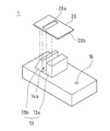
図1は、本発明の端子ボックスの一実施の形態を示しており、(a)は概略断面図、(b)は平面図である。また、図2は、端子台部分を分離した状態で示した斜視図である。ただし、端子ボックスは、正極集電部20の立ち上がり端子部122a、及び負極集電部21の立ち上がり端子部123aのそれぞれに取り付けられるものであるが、その取り付け構造は同じであるので、本実施形態では、正極集電部20の立ち上がり端子部122aに取り付けた場合について説明する。
<Description of terminal box>
1A and 1B show an embodiment of a terminal box according to the present invention, in which FIG. 1A is a schematic sectional view and FIG. 1B is a plan view. FIG. 2 is a perspective view showing the terminal block portion in a separated state. However, although the terminal box is attached to each of the rising
本実施形態の端子ボックス1は、太陽電池ストリング116の裏面からバックフィルム125を貫通して引き出された立ち上がり端子部(以下、出力リード線ともいう)122aを電気的に接続するために、太陽電池ストリング116のバックフィルム125上に載置固定されるボックスケース11と、このボックスケース11上に形成された端子台20とからなっている。また、ボックスケース11は、太陽電池ストリング116のバックフィルム125上に載置固定されるケース本体12と、このケース本体12の上部に前記端子台20を載置固定するための端子台固定部13とからなっている。
The
本実施形態では、ボックスケース11は、図1(b)中左右方向に長く、幅方向に短い直方体形状に形成されており、端子台固定部13は、全体として略立方体形状に形成されている。
In the present embodiment, the
このようなボックスケース11の構成において、本実施形態では、出力リード線122aを端子台20の上方まで通すための開口部14(14a,14b,20a)が、ケース本体11の底面から端子台20の上面まで一連に形成されている。すなわち、出力リード線122aを通すための開口部は一つだけであり、従来技術1のように、本体挿通穴104と端子台挿通穴112とが個別に設けられた構成ではないので、従来技術1の端子ボックスのような無駄なスペースを無くすことができ、端子ボックス自体を小型化することができる。
In such a configuration of the
ここで、本実施形態では、端子台固定部13に形成される開口部14aは、図2に示すように、ケース本体11の左右方向に所定の間隔を存して立設された一対の端子台固定片13a,13bによって形成され、この端子台固定片13a,13bの間が、出力リード線122aを通すための開口部14aとなっている。すなわち、端子台固定部3に形成される開口部14aは、円筒形のようないわゆる穴ではなく、左右両側が開放された溝のような構造となっている。そのため、この端子ボックス1に出力リード線122a及び図示
しない外部出力線(隣接配置される他の太陽電池モジュールと接続するための線)を接続した後、ポッティングによって樹脂封止するとき、ポッティング材が開口部14aからケース本体11の開口部14b内部に(さらには、太陽電池ストリング116のバックフィルム125まで)流入し易くなり、太陽電池ストリング116のバックフィルム125から引き出された出力リード線122aの周辺を確実に樹脂封止することが可能となる。
Here, in this embodiment, the
なお、このような開口部14aの形状に合わせて、端子台20の開口部20aも、幅方向に長い長方形状となっている。
Note that the
また、本実施形態では、ケース本体11に形成された開口部14bは、平面からみて四角形状に形成されており、各内壁面は、端子台固定部13に連通する側(すなわち、開口部14aの下端縁)からケース本体11の底面に向かって漸次拡開するテーパ状に形成されている。このようにテーパ状に形成することで、出力リード線122aを挿通する開口部14bの下端部の口径が大きくなることから、端子ボックス1を上から被せるとき、出力リード線122aが開口部14bの縁部に当たって折れ曲がってしまうといった不具合を防止することができる。
Moreover, in this embodiment, the
また、本実施形態では、端子台20は、端子台固定部13の上面形状に合わせて四角形状に形成されているが、一方の縁部20bが、出力リード線122aの先端部122a1を折り曲げ係止可能なように、端子台固定部13から突出して設けられている。すなわち、本実施形態では、端子台20の開口部20aから上方に突出した出力リード線122aをそのまま開口部20aの縁部に押し当てるようにして端子台20の一方の縁部側(図1では右側)に折り曲げ、その折り曲げ先端部をさら端子台20の一方の縁部20bに押し当てるようにして、下方に折り返すまで折り曲げることにより、出力リード線122aの先端部122a1を端子台20に係止固定することが可能となる。すなわち、端子台20の開口部20aの縁部、及び端子台20の一方の縁部20bの2点をそれぞれ折り曲げ起点として、2回の折り曲げ工程を実施するだけで、出力リード線122aの先端部122a1を端子台20に確実に係止固定することが可能となる。これにより、出力リード線122aの折り曲げ部分を端子台20に半田付けする次の工程を安定して行うことが可能となり、IEC規格に十分準拠した端子ボックスの取り付け構造とすることができる。また、従来技術のような半田付けのための出力リード線の引き回しスペースが不要となるため、端子ボックスに設けられるダイオードや他の配線などの配置自由度も高めることができるといった利点がある。
In the present embodiment, the
また、本実施形態では、ケース本体11の適所に、底面から上面まで達する空気抜き孔16を設けた構成としてもよい。ただし、この空気孔16は、端子台固定部13から十分離れた位置に設けるものとする。端子ボックス1を太陽電池ストリング116のバックフィルム125に取り付けるため、端子ボックス1のケース本体12の底面には、その周囲(全周であっても、例えば隅角部の4箇所等であってもよい)に接着用のシリコン樹脂18が塗布されている。従って、端子ボックス1を太陽電池ストリング116のバックフィルム125上に接着固定すると、このシリコン樹脂18の厚み分だけ、ケース本体12の底面と太陽電池ストリング116のバックフィルム125との間に隙間Sができることになる。従って、空気抜き孔16を設けることで、ポッティング材が開口部14に流れ込むとき、開口部14内部及び太陽電池ストリング116のバックフィルム125と端子ボックス1のケース本体12の底面との隙間Sに存在している空気が、空気抜き孔16から外部に抜けるため、ポッティング材を開口部14内(より具体的には、開口部14内の太陽電池ストリング116のバックフィルム125まで、さらには太陽電池ストリング116のバックフィルム125と端子ボックス1のケース本体12の底面との隙間Sまで)確実に充填することができ、空隙の無い樹脂封止を行うことが可能となる。
Moreover, in this embodiment, it is good also as a structure which provided the
なお、図示は省略しているが、この端子台20に固定される外部出力線の固定方法としては、外部出力線の接続端部を端子台20の他方の端部にリベット等を用いて直接かしめるようにすればよい。このように、太陽電池ストリング116のバックフィルム125上に端子ボックス1を取り付けて、端子台20に出力リード線122aを電気的に接続し、さらに、この端子台20に外部出力線を電気的に接続することで、太陽電池モジュールが作製される。
Although not shown, the external output line fixed to the
1 端子ボックス
11 ボックスケース
12 ケース本体
13 端子台固定部
13a,13b 端子台固定片
14(14a,14b,20a) 開口部
16 空気抜き孔
20 端子台
20b 一方の縁部
111 透光性絶縁基板
115 太陽電池セル
116 太陽電池ストリング(薄膜太陽電池ストリング)
117 P型電極端子部
118 N型電極端子部
119 絶縁膜
120 正極集電部
121 負極集電部
122 正極リード線
123 負極リード線
122a,123a 立ち上がり端子部
122a1 先端部
124 封止絶縁フィルム
125 バックフィルム
124a,125a 貫通孔
DESCRIPTION OF
117 P-type electrode terminal portion 118 N-type
Claims (6)
前記バックフィルム上に載置固定されるボックスケースと、このボックスケース上に形成された前記出力リード線を電気的に接続する端子台とからなり、前記ボックスケースはさらに、前記バックフィルム上に載置固定されるケース本体と、このケース本体の上部に前記端子台を載置固定するための端子台固定部とからなり、
前記出力リード線を前記端子台の上方まで通すための開口部が前記ケース本体の底面から前記端子台の上面まで一連に形成されていることを特徴とする端子ボックス。 A terminal box for electrically connecting the output lead wire connected to the electrode of the solar battery cell and drawn through the back film,
A box case that is placed and fixed on the back film; and a terminal block that electrically connects the output lead wires formed on the box case. The box case is further placed on the back film. A case body to be fixed and a terminal block fixing portion for mounting and fixing the terminal block on the upper portion of the case body;
An opening for passing the output lead wire to above the terminal block is formed in series from the bottom surface of the case body to the upper surface of the terminal block.
前記ケース本体に形成された前記開口部は、前記端子台固定部に連通する側から前記ケース本体の底面に向かって漸次拡開するテーパ状の貫通穴からなることを特徴とする端子ボックス。 The terminal box according to claim 1,
The terminal box, wherein the opening formed in the case body is formed of a tapered through hole that gradually expands from a side communicating with the terminal block fixing portion toward a bottom surface of the case body.
前記端子台の一方の縁部が、前記出力リード線の先端部を折り曲げ係止可能なように前記端子台固定部から突出して設けられていることを特徴とする端子ボックス。 In the terminal box according to claim 1 or 2,
One terminal portion of the terminal block is provided so as to protrude from the terminal block fixing portion so that a tip end portion of the output lead wire can be bent and locked.
前記端子台固定部は、前記ケース本体の前後方向に所定の間隔を存して立設された一対の端子台固定片によって形成され、この端子台固定片の間が前記出力リード線を通すための開口部となっていることを特徴とする端子ボックス。 In the terminal box of any one of Claim 1 to Claim 3,
The terminal block fixing portion is formed by a pair of terminal block fixing pieces erected at a predetermined interval in the front-rear direction of the case body, and the output lead wire is passed between the terminal block fixing pieces. A terminal box characterized by having an opening.
前記ケース本体に、当該ケース本体の底面から上面まで達する空気抜き孔が設けられていることを特徴とする端子ボックス。 In the terminal box according to any one of claims 1 to 4,
An air vent hole extending from the bottom surface to the top surface of the case body is provided in the case body.
前記端子ボックスは、前記バックフィルム上に載置固定されるボックスケースと、このボックスケース上に形成された前記出力リード線を電気的に接続する端子台とからなり、前記ボックスケースはさらに、前記バックフィルム上に載置固定されるケース本体と、このケース本体の上部に前記端子台を載置固定するための端子台固定部とからなり、
前記出力リード線を前記端子台の上方まで通すための開口部が前記ケース本体の底面から前記端子台の上面まで一連に形成されていることを特徴とする太陽電池モジュール。 A solar cell module comprising a terminal box that is electrically connected to an output lead wire connected to an electrode of a solar cell and drawn through a back film,
The terminal box includes a box case that is placed and fixed on the back film, and a terminal block that electrically connects the output lead wire formed on the box case, and the box case further includes: It consists of a case main body placed and fixed on the back film, and a terminal block fixing portion for mounting and fixing the terminal block on the upper portion of the case main body,
An opening for passing the output lead wire to above the terminal block is formed in a series from the bottom surface of the case body to the upper surface of the terminal block.
Priority Applications (1)
| Application Number | Priority Date | Filing Date | Title |
|---|---|---|---|
| JP2009219624A JP5132646B2 (en) | 2009-09-24 | 2009-09-24 | Terminal box and solar cell module |
Applications Claiming Priority (1)
| Application Number | Priority Date | Filing Date | Title |
|---|---|---|---|
| JP2009219624A JP5132646B2 (en) | 2009-09-24 | 2009-09-24 | Terminal box and solar cell module |
Related Parent Applications (1)
| Application Number | Title | Priority Date | Filing Date |
|---|---|---|---|
| JP2008147024A Division JP4384241B1 (en) | 2008-06-04 | 2008-06-04 | Terminal box and solar cell module |
Related Child Applications (1)
| Application Number | Title | Priority Date | Filing Date |
|---|---|---|---|
| JP2012006946A Division JP5306490B2 (en) | 2012-01-17 | 2012-01-17 | Terminal box and solar cell module |
Publications (3)
| Publication Number | Publication Date |
|---|---|
| JP2010004068A true JP2010004068A (en) | 2010-01-07 |
| JP2010004068A5 JP2010004068A5 (en) | 2010-10-21 |
| JP5132646B2 JP5132646B2 (en) | 2013-01-30 |
Family
ID=41585464
Family Applications (1)
| Application Number | Title | Priority Date | Filing Date |
|---|---|---|---|
| JP2009219624A Active JP5132646B2 (en) | 2009-09-24 | 2009-09-24 | Terminal box and solar cell module |
Country Status (1)
| Country | Link |
|---|---|
| JP (1) | JP5132646B2 (en) |
Cited By (2)
| Publication number | Priority date | Publication date | Assignee | Title |
|---|---|---|---|---|
| JP2012234850A (en) * | 2011-04-28 | 2012-11-29 | Angel Kogyo Kk | Solar cell module with terminal box, and terminal box |
| WO2018062185A1 (en) * | 2016-09-29 | 2018-04-05 | パナソニックIpマネジメント株式会社 | Solar cell module and method for manufacturing solar cell module |
Citations (5)
| Publication number | Priority date | Publication date | Assignee | Title |
|---|---|---|---|---|
| JPH0212878A (en) * | 1988-04-11 | 1990-01-17 | Westinghouse Electric Corp <We> | Photocell module |
| JP2005353734A (en) * | 2004-06-09 | 2005-12-22 | Sumitomo Wiring Syst Ltd | Terminal box for solar cell module |
| JP2006041262A (en) * | 2004-07-28 | 2006-02-09 | Sumitomo Wiring Syst Ltd | Terminal box for solar cell module |
| JP2006269803A (en) * | 2005-03-24 | 2006-10-05 | Mitsubishi Electric Corp | Terminal box device for solar cell module |
| JP2006310439A (en) * | 2005-04-27 | 2006-11-09 | Yukita Electric Wire Co Ltd | Terminal box for solar cell module |
-
2009
- 2009-09-24 JP JP2009219624A patent/JP5132646B2/en active Active
Patent Citations (5)
| Publication number | Priority date | Publication date | Assignee | Title |
|---|---|---|---|---|
| JPH0212878A (en) * | 1988-04-11 | 1990-01-17 | Westinghouse Electric Corp <We> | Photocell module |
| JP2005353734A (en) * | 2004-06-09 | 2005-12-22 | Sumitomo Wiring Syst Ltd | Terminal box for solar cell module |
| JP2006041262A (en) * | 2004-07-28 | 2006-02-09 | Sumitomo Wiring Syst Ltd | Terminal box for solar cell module |
| JP2006269803A (en) * | 2005-03-24 | 2006-10-05 | Mitsubishi Electric Corp | Terminal box device for solar cell module |
| JP2006310439A (en) * | 2005-04-27 | 2006-11-09 | Yukita Electric Wire Co Ltd | Terminal box for solar cell module |
Cited By (2)
| Publication number | Priority date | Publication date | Assignee | Title |
|---|---|---|---|---|
| JP2012234850A (en) * | 2011-04-28 | 2012-11-29 | Angel Kogyo Kk | Solar cell module with terminal box, and terminal box |
| WO2018062185A1 (en) * | 2016-09-29 | 2018-04-05 | パナソニックIpマネジメント株式会社 | Solar cell module and method for manufacturing solar cell module |
Also Published As
| Publication number | Publication date |
|---|---|
| JP5132646B2 (en) | 2013-01-30 |
Similar Documents
| Publication | Publication Date | Title |
|---|---|---|
| JP4384241B1 (en) | Terminal box and solar cell module | |
| JP4558070B2 (en) | Solar cell module | |
| US8952240B2 (en) | Solar cell module | |
| US8921684B2 (en) | Solar cell module and manufacturing method thereof | |
| JP5031698B2 (en) | Solar cell module | |
| WO2011024993A1 (en) | Solar cell module | |
| JP2011054661A (en) | Solar cell module | |
| JP4245724B2 (en) | Solar cell module | |
| US20110271998A1 (en) | Solar cell module and manufacturing method thereof | |
| JP5132646B2 (en) | Terminal box and solar cell module | |
| JP2010283231A (en) | Solar cell module and method of manufacturing the same | |
| JP2012019023A (en) | Solar cell module assembly and moving body equipped with the same | |
| JP5306490B2 (en) | Terminal box and solar cell module | |
| WO2012090694A1 (en) | Solar cell module | |
| JPH11303325A (en) | Solar battery module | |
| JP4687067B2 (en) | Solar cell module and power lead wire connection method | |
| JP2002141535A (en) | Method of taking out power leads of solar cell module | |
| JP2012064745A (en) | Solar cell module | |
| JP2003017732A (en) | Method of leading out power lead of solar battery module | |
| JP2012142635A (en) | Solar cell module | |
| JP2012142634A (en) | Solar cell module and manufacturing method of the same | |
| JP2012142637A (en) | Solar cell module | |
| JP2010187017A (en) | Solar cell module and method of manufacturing the same | |
| JP2012142636A (en) | Solar cell module and manufacturing method of the same | |
| JP2012142633A (en) | Solar cell module and manufacturing method of the same |
Legal Events
| Date | Code | Title | Description |
|---|---|---|---|
| A521 | Request for written amendment filed |
Free format text: JAPANESE INTERMEDIATE CODE: A523 Effective date: 20100831 |
|
| A621 | Written request for application examination |
Free format text: JAPANESE INTERMEDIATE CODE: A621 Effective date: 20100831 |
|
| TRDD | Decision of grant or rejection written | ||
| A01 | Written decision to grant a patent or to grant a registration (utility model) |
Free format text: JAPANESE INTERMEDIATE CODE: A01 Effective date: 20121016 |
|
| A01 | Written decision to grant a patent or to grant a registration (utility model) |
Free format text: JAPANESE INTERMEDIATE CODE: A01 |
|
| A61 | First payment of annual fees (during grant procedure) |
Free format text: JAPANESE INTERMEDIATE CODE: A61 Effective date: 20121106 |
|
| FPAY | Renewal fee payment (event date is renewal date of database) |
Free format text: PAYMENT UNTIL: 20151116 Year of fee payment: 3 |
|
| R150 | Certificate of patent or registration of utility model |
Free format text: JAPANESE INTERMEDIATE CODE: R150 Ref document number: 5132646 Country of ref document: JP Free format text: JAPANESE INTERMEDIATE CODE: R150 |