JP2010002045A - Fluid leak detector for marine hose - Google Patents
Fluid leak detector for marine hose Download PDFInfo
- Publication number
- JP2010002045A JP2010002045A JP2008163840A JP2008163840A JP2010002045A JP 2010002045 A JP2010002045 A JP 2010002045A JP 2008163840 A JP2008163840 A JP 2008163840A JP 2008163840 A JP2008163840 A JP 2008163840A JP 2010002045 A JP2010002045 A JP 2010002045A
- Authority
- JP
- Japan
- Prior art keywords
- fluid
- hose
- casing
- leak detector
- detector
- Prior art date
- Legal status (The legal status is an assumption and is not a legal conclusion. Google has not performed a legal analysis and makes no representation as to the accuracy of the status listed.)
- Granted
Links
Images


Abstract
Description
本発明は、マリンホースの流体漏れ検知器に関し、さらに詳しくは、オイルポッドを用いる構造でありながら、無色透明の流体であっても、漏れの発生を確実に目視検知できるようにしたマリンホースの流体漏れ検知器に関するものである。 The present invention relates to a marine hose fluid leak detector, and more specifically, a marine hose that has a structure using an oil pod and can reliably detect the occurrence of leakage even with a colorless and transparent fluid. The present invention relates to a fluid leak detector.
海上のタンカーと陸上施設との間を連結して原油等を海上輸送するマリンホースは、破損等して輸送流体がホース外部へ漏出すれば、多大な環境汚染を引き起こすことになるため、種々の漏出防止手段が講じられている。例えば、流体流路の外周側に積層した補強層の間に流体滞留層を設け、漏出した輸送流体を一時的に流体滞留層に貯留できるようにしてホース外部への漏出を防止するようにしている。 A marine hose that transports crude oil etc. by sea between a tanker on the sea and an onshore facility will cause a great deal of environmental pollution if the transport fluid leaks outside the hose due to breakage, etc. Leakage prevention measures are taken. For example, a fluid retention layer is provided between the reinforcing layers laminated on the outer peripheral side of the fluid flow path so that the leaked transport fluid can be temporarily stored in the fluid retention layer to prevent leakage outside the hose. Yes.
この流体滞留層に漏れ出た輸送流体を検知するために、例えば、オイルポッドを利用した流体漏れ検知器が知られている(特許文献1参照)。この流体漏れ検知器では、流体滞留層に漏れ出た輸送流体が、連通管を通じてオイルポッドに浸入してくるので、オイルポッドの内部に収容した圧潰部材の圧潰の有無や、濡れ部材の濡れの有無を目視検知することで、流体漏れが生じているか否かを確認することができる。その他、複雑な機構を設けることも提案されている。 In order to detect the transport fluid leaking into the fluid retention layer, for example, a fluid leak detector using an oil pod is known (see Patent Document 1). In this fluid leak detector, since the transport fluid leaking into the fluid retention layer enters the oil pod through the communication pipe, the presence or absence of crushing of the crushing member housed inside the oil pod and the wetting of the wetting member By visually detecting the presence or absence, it can be confirmed whether or not fluid leakage has occurred. In addition, it has also been proposed to provide a complicated mechanism.
しかしながら、所定圧力で圧潰部材が確実に圧潰するように設定することは難しく、複雑な機構を用いれば、正常に機能しなくなるリスクが増大するため、なるべく簡素な構造にすることが望ましい。また、濡れ部材の濡れの有無を水中で目視確認することは困難な作業になる。このようなオイルポッドを利用した構造の場合には、特に、輸送流体がガソリンやディーゼル等の無色透明の流体であると、オイルポッド内の流体の有無を目視で確認することが難しいため、流体漏れ検知に対する確実性に欠けるという問題があった。
本発明の目的は、オイルポッドを用いる構造でありながら、無色透明の流体であっても、漏れの発生を確実に目視検知できるようにしたマリンホースの流体漏れ検知器を提供することにある。 An object of the present invention is to provide a marine hose fluid leak detector that can reliably detect the occurrence of leakage even with a colorless and transparent fluid, even though the structure uses an oil pod.
上記目的を達成するため本発明のマリンホースの流体漏れ検知器は、流体流路の外周側で周方向に積層された補強層の間に形成された流体滞留層に接続する連通管をホースの外部まで延設し、内部を透視できる窓部を有する中空のケーシングを、前記連通管に連通させてホース表面に設けたマリンホースの流体漏れ検知器において、流体流路を通過する輸送流体よりも比重が小さい検出体、輸送流体に接触することにより変色する検出体、輸送流体に接触することにより膨潤する検出体、輸送流体に接触することにより溶解する検出体のうち、少なくとも1種類の検出体を前記ケーシング内に収容することを特徴とするものである。 In order to achieve the above object, a fluid leak detector for a marine hose according to the present invention has a communication pipe connected to a fluid retention layer formed between reinforcing layers laminated in the circumferential direction on the outer peripheral side of a fluid flow path. In a marine hose fluid leak detector that is provided on the hose surface with a hollow casing that extends to the outside and has a window portion through which the inside can be seen, than the transport fluid that passes through the fluid flow path. At least one type of detection body among a detection body having a small specific gravity, a detection body that changes color by contact with the transport fluid, a detection body that swells by contact with the transport fluid, and a detection body that dissolves by contact with the transport fluid Is housed in the casing.
ここで、前記ケーシングを角度調整手段を介してホース表面に取付けることもできる。この際に、前記角度調節手段を、ホース表面からホース半径方向に突設した支軸まわりに回転可能に設けることもできる。また、前記輸送流体よりも比重が小さい検出体とともに、輸送流体よりも比重の大きい非浮体をケーシング内に収容することもできる。前記検出体の表面に反射体を設けることもできる。 Here, the casing can be attached to the hose surface via an angle adjusting means. At this time, the angle adjusting means can be provided so as to be rotatable around a support shaft protruding from the hose surface in the hose radial direction. A non-floating body having a specific gravity larger than that of the transport fluid can be accommodated in the casing together with the detection body having a specific gravity smaller than that of the transport fluid. A reflector may be provided on the surface of the detection body.
本発明のマリンホースの流体漏れ検知器によれば、流体滞留層に接続する連通管をホースの外部まで延設し、この連通管に内部を透視できる窓部を有する中空のケーシング(オイルポッド)を連通させてホース表面に設け、このケーシング内に無色透明な輸送流体であっても、その輸送流体の有無を検出できる検出体を収容することにより、ホースが破損した際には、流体滞留層に漏れ出してケーシング内に浸入する輸送流体によって検出体に変化が生じる。 According to the fluid leak detector of the marine hose of the present invention, a hollow casing (oil pod) having a communication pipe connected to the fluid retention layer extending to the outside of the hose and having a window portion through which the inside can be seen through. Even if it is a colorless and transparent transport fluid in this casing, a detector that can detect the presence or absence of the transport fluid is housed in this casing. The detection body changes due to the transport fluid that leaks into the casing and enters the casing.
例えば、輸送流体よりも比重が小さい検出体を用いた場合には、ケーシング内に浸入した輸送流体が検出体を浮かせる。輸送流体に接触することにより変色する検出体を用いた場合には、ケーシング内に浸入した輸送流体が検出体を変色させる。輸送流体に接触することにより膨潤する検出体を用いた場合には、ケーシング内に浸入した輸送流体が検出体を膨潤変形させる。輸送流体に接触することにより溶解する検出体を用いた場合には、ケーシング内に浸入した輸送流体が検出体を溶解させて小さく、或いは消滅させる。 For example, when a detection body having a specific gravity smaller than that of the transport fluid is used, the transport fluid that has entered the casing causes the detection body to float. When a detection body that changes color by contact with the transport fluid is used, the transport fluid that has entered the casing changes the color of the detection body. When a detection body that swells by contact with the transport fluid is used, the transport fluid that has entered the casing swells and deforms the detection body. In the case of using a detection body that dissolves by contact with the transport fluid, the transport fluid that has entered the casing dissolves the detection body to make it small or disappear.
このような検出体の変化を目視確認することで、無色透明な流体であっても、漏れの発生を確実に目視検知することが可能になる。 By visually confirming such a change in the detection body, it is possible to reliably visually detect the occurrence of leakage even with a colorless and transparent fluid.
以下、本発明のマリンホースの流体漏れ検知器を図に示した実施形態に基づいて説明する。 Hereinafter, the fluid leak detector of the marine hose of the present invention will be described based on the embodiments shown in the drawings.
図1〜図5に示すように、マリンホース1は、両端に別のマリンホース1を連結する連結端部2を備え、連結端部2は一端にフランジ2aを備えたニップル2bで構成されている。ニップル2bの外周には周方向内側から外側に向かって、内面ゴム層3、主補強層4、本体ワイヤ層5、補助補強層6が順に巻付けられて積層され、最外周がカバーゴム層8で覆われている。本体ワイヤ層5と補助補強層6との層間には、密閉空間となる流体滞留層7が形成され、内面ゴム層3の内周側が流体流路1aとなっている。
As shown in FIGS. 1-5, the
輸送流体に接する内面ゴム層3は、耐油性に優れたニトリルゴム等で構成され、本体ワイヤ層5は、主補強層4の外周のゴム層に金属ワイヤを所定間隔をあけて螺旋状に巻付けて構成されている。それぞれの補強層4、6は補強コードをゴムで被覆した複数の補強コード層を積層して構成されている。
The
主補強層4、本体ワイヤ層5、補助補強層6は、それぞれの一端部のニップルワイヤ4a、5a、6aと、ニップル2bの外周面に突設された固定リング2c等により、ニップル2bに固定されている。カバーゴム層8は、ゴム等の非透水性材料で構成され、かつ表面には視認性に優れたライン模様等が付されている。
The main reinforcing layer 4, the main
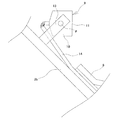
流体滞留層7は、主補強層4から漏れ出した輸送流体を一時的に貯留するように機能する。流体滞留層7には、連通管14の一方端部が接続し、他方端部はホース外部まで延設されている。このように、流体滞留層7からニップル2bの外周上をフランジ2aの方向に延びる連通管14は、ニップル2bの外周面に設けられた流体漏れ検知器9(以下、検知器9という)に接続されている。
The
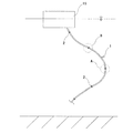
マリンホース1の中でも、サブマリンホースの場合には、図2に例示するように海上のタンカー15に連結されて、水中で上下に延設されている状態になることもあり、水中に沈んだまま、左右に横たわって延設されているような状態になることもある。一方、フローティングホースの場合には、補助補強層6とカバーゴム層8の層間に浮力材層が設けられて海上に浮かんだ状態で左右に横たわって延設された状態になる。本発明の検知器9は、サブマリンホースおよびフローティングホースの両タイプに適用することができる。
Among the
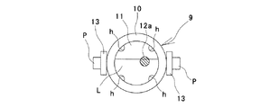
検知器9は、内部を透視できる窓部11を有する中空のケーシング10(いわゆるオイルポッド)と、ケーシング10の内部に収容された浮体12aとを備えている。浮体12aは、流体流路1aを通過する輸送流体よりも比重が小さくなっている。即ち、この実施形態では、浮体12aを検出体として用いている。
The
浮体12aは、例えば、熱可塑樹脂(ポリカーボネート、ナイロン等)、熱硬化樹脂等で形成し、直径3mm〜10mm程度の球体にして、色は蛍光色にすることが好ましい。ケーシング10に収容する浮体12aの数は、1つに限らず、2個、3個等、複数にすることもできる。
The
ケーシング10の底部に連結する連通管14と、ケーシング10の内部とは、ケーシング10に形成された流入孔hによって連通している。したがって、主補強層4が破損して、流体滞留層7に漏れ出た輸送流体は、連通管14を通じてケーシング10内に浸入するようになっている。
The
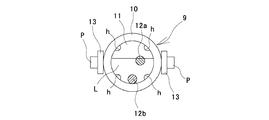
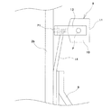
検知器9は、ニップル2bの外周面に固定された可動ブラケット13を介して取付けられている。ケーシング10は、角度調整手段である可動ブラケット13の支軸Pによって軸支されているので、図3に例示するように、マリンホース1が上下垂直状態の場合であっても、図4に例示するようにマリンホース1が傾斜状態の場合であっても、マリンホース1の状態に関らず、支軸Pまわりに回転させることにより、検知器9の窓部11を垂直状態にすることができる構造になっている。検知器9は、ホース表面に取付け角度が変更できないように不動状態に固定することもできるが、上記のように角度調整手段を介してホース表面に取付けることが好ましい。
The
ここで、主補強層4が破損して流体滞留層7に輸送流体が漏れ出た際には、漏れ出た輸送流体がケーシング10内に浸入するので、図5の状態にあった浮体12aを、浸入した輸送流体が、図6に例示するように浮かせることになる。そのため、輸送流体がガソリンやディーゼル等の無色透明の流体であっても、漏れの発生を目視検知可能になる。
Here, when the main reinforcing layer 4 breaks and the transport fluid leaks into the
また、ケーシング10は、マリンホース1の状態に応じて、可動ブラケット13によって取付け角度を調整して窓部11を垂直状態にできるので、輸送流体に浮いている浮体12aをケーシング10内の上方に浮上させることができる。即ち、マリンホース1が横たわるように左右に延設されている状態であっても、浮体12aの浮沈状態を容易に目視確認できる状態にすることができる。
Moreover, since the
このように、本発明によれば、オイルポッドを用いた構造でありながら、無色透明の流体であっても、ケーシング10内の浮体12aの浮沈状態を容易に目視確認することができ、輸送流体の漏れの発生を確実に目視検知することが可能になる。目視検知が困難な水中であっても、確認作業が容易に行えるようになる。
As described above, according to the present invention, the floating state of the floating
図7、図8に例示するように、ケーシング10には、浮体12aとともに、輸送流体よりも比重の大きい非浮体12bを収容してもよい。浮体12aと非浮体12bとは、色や形状を異ならせて識別容易にしておく。この場合には、輸送流体がケーシング10内に浸入すると、浮体12aのみが浮くので、浮体12aの浮沈状態が一段と目視確認し易くなる。
As illustrated in FIGS. 7 and 8, the
図9に例示するように、浮体12aの表面に反射体Rを設けることもできる。例えば、浮体12aの表面の全体或いは、一部に反射塗料を塗布したり、反射材を付着させる。水中では、水上に比して暗く、また、夜間においては、浮体12aの浮沈状態を目視検知し難くなる。また、経時的に窓部11が汚れてケーシング10の内部が透視し難くなるが、反射体Rを設けることにより、光を照らせば浮体12aの浮沈状態の確認を容易にすることができる。
As illustrated in FIG. 9, a reflector R can be provided on the surface of the floating
図10に例示するように、可動ブラケット13をホース表面(ニップル2b)からホース半径方向に突設した支軸P1まわりに回転可能に設けることもできる。この構成によれば、マリンホース1がねじれた状態や屈曲した状態など、マリンホース1のあらゆる状態に応じて、可動ブラケット13を支軸P1まわりに回転させるとともに、ケーシング10を支軸Pまわりに回転させることにより、窓部11を垂直状態に設定して、輸送流体に浮かぶ浮体12aをケーシング10の上方に浮上させることができる。そのため、浮体12aの浮沈状態を容易に目視確認することができる。
As illustrated in FIG. 10, the
上記実施形態では、検出体として浮体12aを採用しているが、これに限定されるものではない。輸送流体よりも比重の小さい検出体(浮体12a)、輸送流体に接触することにより変色する検出体、輸送流体に接触することにより膨潤する検出体、輸送流体に接触することにより溶解する検出体のうち、少なくとも1種類の検出体をケーシング10内に収容することができる。
In the embodiment described above, the floating
輸送流体に接触することにより変色する検出体とは、輸送流体に溶けやすい塗料で検出体表面を塗布し、輸送流体に接触した際には塗料が溶解して、その塗料とは異なる色(塗料の下層の色)が出現するようにしたものを例示できる。或いは、輸送流体の性質によって変色する試薬を検出体表面に塗布したものを例示できる。この検出体を用いた場合には、ケーシング10内に浸入した輸送流体が検出体を変色させる。輸送流体に接触することにより変色する検出体とともに、変色しない検出体をケーシング10内に収容してもよい。
The detection body that changes color when in contact with the transport fluid is applied to the surface of the detection body with a paint that is easily soluble in the transport fluid. For example, a color in which the lower layer color) appears. Or what applied the reagent discolored by the property of a transport fluid to the detection body surface can be illustrated. When this detection body is used, the transport fluid that has entered the
輸送流体に接触することにより膨潤する検出体とは、輸送流体に対して膨潤性の高い材料(樹脂、ゴム等の有機化合物)によって形成したものを例示できる。この検出体を用いた場合には、ケーシング10内に浸入した輸送流体が検出体を膨潤させて形状(大きさ)を変化させる。輸送流体に接触することにより膨潤する検出体とともに、膨潤しない検出体をケーシング10内に収容してもよい。
Examples of the detection body that swells by contact with the transport fluid include those formed of materials (organic compounds such as resin and rubber) that are highly swellable with respect to the transport fluid. When this detection body is used, the transport fluid that has entered the
輸送流体に接触することにより溶解する検出体としては、輸送流体がガソリンの場合には、ポリスチレン(スチロール樹脂)によって形成したものを例示できる。この検出体を用いた場合には、ケーシング10内に浸入した輸送流体が検出体を溶解させて小さくする、或いは消滅させる。輸送流体に接触することにより溶解する検出体とともに、溶解しない検出体をケーシング10内に収容してもよい。
As a detection body which melt | dissolves by contacting a transport fluid, when the transport fluid is gasoline, what was formed with polystyrene (styrene resin) can be illustrated. When this detection body is used, the transport fluid that has entered the
上記した各種類の検出体を用いても、検出体の変化を容易に目視確認することができるので、無色透明な輸送流体であっても、漏れの発生を確実に目視検知することが可能になる。 Even with the above-mentioned types of detectors, changes in the detectors can be easily visually confirmed, so that the occurrence of leakage can be reliably visually detected even with colorless and transparent transport fluids. Become.
マリンホース1の内部構造は、仕様により補強層の数や積層体の種類が異なり、実施形態で例示した構造に限らず、流体滞留層7を備えた種々の構造のマリンホース1に対して、本発明を適用することができる。また、本発明は、無色透明な流体だけでなく、有色の流体に対しても用いることができる。
The internal structure of the
1 マリンホース
1a 流体流路
2 連結端部
2a フランジ
2b ニップル
2c 固定リング
3 内面ゴム層
4 主補強層
4a ニップルワイヤ
5 本体ワイヤ層
5a ニップルワイヤ
6 補助補強層
6a ニップルワイヤ
7 流体滞留層
8 カバーゴム層
9 流体漏れ検知器
10 ケーシング
11 窓部
12a 浮体(検出体)
12b 非浮体
13 可動ブラケット(角度調整手段)
14 連通管
15 タンカー
P、P1 支軸
h 流入孔
R 反射体
DESCRIPTION OF
14
Claims (5)
Priority Applications (1)
| Application Number | Priority Date | Filing Date | Title |
|---|---|---|---|
| JP2008163840A JP4872972B2 (en) | 2008-06-23 | 2008-06-23 | Marine hose fluid leak detector |
Applications Claiming Priority (1)
| Application Number | Priority Date | Filing Date | Title |
|---|---|---|---|
| JP2008163840A JP4872972B2 (en) | 2008-06-23 | 2008-06-23 | Marine hose fluid leak detector |
Publications (2)
| Publication Number | Publication Date |
|---|---|
| JP2010002045A true JP2010002045A (en) | 2010-01-07 |
| JP4872972B2 JP4872972B2 (en) | 2012-02-08 |
Family
ID=41583919
Family Applications (1)
| Application Number | Title | Priority Date | Filing Date |
|---|---|---|---|
| JP2008163840A Expired - Fee Related JP4872972B2 (en) | 2008-06-23 | 2008-06-23 | Marine hose fluid leak detector |
Country Status (1)
| Country | Link |
|---|---|
| JP (1) | JP4872972B2 (en) |
Cited By (2)
| Publication number | Priority date | Publication date | Assignee | Title |
|---|---|---|---|---|
| ES2503515R1 (en) * | 2013-04-03 | 2014-11-06 | Abn Pipe Systems, S.L.U. | PIPING FOR FLUID DRIVING. |
| CN112539894A (en) * | 2019-09-20 | 2021-03-23 | 横滨橡胶株式会社 | Fluid leakage sensing system for marine hose |
Citations (2)
| Publication number | Priority date | Publication date | Assignee | Title |
|---|---|---|---|---|
| JP2003156180A (en) * | 2001-11-16 | 2003-05-30 | Yokohama Rubber Co Ltd:The | Fluid transfer hose and its leakage fluid monitoring method |
| JP2007516383A (en) * | 2003-12-03 | 2007-06-21 | テイラー マクラレン リミテッド | Inundation detection system |
-
2008
- 2008-06-23 JP JP2008163840A patent/JP4872972B2/en not_active Expired - Fee Related
Patent Citations (2)
| Publication number | Priority date | Publication date | Assignee | Title |
|---|---|---|---|---|
| JP2003156180A (en) * | 2001-11-16 | 2003-05-30 | Yokohama Rubber Co Ltd:The | Fluid transfer hose and its leakage fluid monitoring method |
| JP2007516383A (en) * | 2003-12-03 | 2007-06-21 | テイラー マクラレン リミテッド | Inundation detection system |
Cited By (2)
| Publication number | Priority date | Publication date | Assignee | Title |
|---|---|---|---|---|
| ES2503515R1 (en) * | 2013-04-03 | 2014-11-06 | Abn Pipe Systems, S.L.U. | PIPING FOR FLUID DRIVING. |
| CN112539894A (en) * | 2019-09-20 | 2021-03-23 | 横滨橡胶株式会社 | Fluid leakage sensing system for marine hose |
Also Published As
| Publication number | Publication date |
|---|---|
| JP4872972B2 (en) | 2012-02-08 |
Similar Documents
| Publication | Publication Date | Title |
|---|---|---|
| JP4747834B2 (en) | Marine hose fluid leak detection system | |
| US4775855A (en) | Hose leak detectors | |
| JP7389327B2 (en) | Marine hose fluid leak detection system | |
| US20040177891A1 (en) | Leak detection system and method for offshore hose lines | |
| JP5343696B2 (en) | Fluid transfer hose | |
| JP4872972B2 (en) | Marine hose fluid leak detector | |
| JP7243270B2 (en) | Marine hose fluid leak detection system | |
| JP7389313B2 (en) | Marine hose fluid leak detection system | |
| JP4076338B2 (en) | Fluid transfer hose | |
| JP3982908B2 (en) | Damage detection device for marine hose damage detection | |
| JP3253399B2 (en) | Conveyance leak detection hose | |
| JP7225949B2 (en) | Marine hose fluid leak detector | |
| JP2007139174A (en) | Marine hose | |
| US20220341808A1 (en) | End fitting apparatus and method | |
| JP3817459B2 (en) | Fluid transfer hose | |
| JP4784547B2 (en) | Marine hose hose line monitoring system | |
| JP3565576B2 (en) | Method and apparatus for detecting abnormality in hose line for liquid transport | |
| JP2002181259A (en) | Fluid transporting hose | |
| JP3354621B2 (en) | Transport leak detection hose | |
| JP5343695B2 (en) | Fluid transfer hose | |
| JP4285601B2 (en) | Hose line | |
| JP3496962B2 (en) | hose | |
| HU211047B (en) | Leakage signalling system for hoses mainly for hoses used in oil sea-transport |
Legal Events
| Date | Code | Title | Description |
|---|---|---|---|
| A621 | Written request for application examination |
Free format text: JAPANESE INTERMEDIATE CODE: A621 Effective date: 20090928 |
|
| A977 | Report on retrieval |
Free format text: JAPANESE INTERMEDIATE CODE: A971007 Effective date: 20110217 |
|
| A131 | Notification of reasons for refusal |
Free format text: JAPANESE INTERMEDIATE CODE: A131 Effective date: 20110426 |
|
| A521 | Written amendment |
Free format text: JAPANESE INTERMEDIATE CODE: A523 Effective date: 20110623 |
|
| TRDD | Decision of grant or rejection written | ||
| A01 | Written decision to grant a patent or to grant a registration (utility model) |
Free format text: JAPANESE INTERMEDIATE CODE: A01 Effective date: 20111025 |
|
| A01 | Written decision to grant a patent or to grant a registration (utility model) |
Free format text: JAPANESE INTERMEDIATE CODE: A01 |
|
| A61 | First payment of annual fees (during grant procedure) |
Free format text: JAPANESE INTERMEDIATE CODE: A61 Effective date: 20111107 |
|
| FPAY | Renewal fee payment (prs date is renewal date of database) |
Free format text: PAYMENT UNTIL: 20141202 Year of fee payment: 3 |
|
| R150 | Certificate of patent (=grant) or registration of utility model |
Free format text: JAPANESE INTERMEDIATE CODE: R150 |
|
| FPAY | Renewal fee payment (prs date is renewal date of database) |
Free format text: PAYMENT UNTIL: 20141202 Year of fee payment: 3 |
|
| LAPS | Cancellation because of no payment of annual fees |