JP2009540468A - Multidimensional symbology and related methods - Google Patents
Multidimensional symbology and related methods Download PDFInfo
- Publication number
- JP2009540468A JP2009540468A JP2009515462A JP2009515462A JP2009540468A JP 2009540468 A JP2009540468 A JP 2009540468A JP 2009515462 A JP2009515462 A JP 2009515462A JP 2009515462 A JP2009515462 A JP 2009515462A JP 2009540468 A JP2009540468 A JP 2009540468A
- Authority
- JP
- Japan
- Prior art keywords
- data
- cells
- multidimensional
- symbol
- cell
- Prior art date
- Legal status (The legal status is an assumption and is not a legal conclusion. Google has not performed a legal analysis and makes no representation as to the accuracy of the status listed.)
- Pending
Links
Images
Classifications
-
- G—PHYSICS
- G06—COMPUTING OR CALCULATING; COUNTING
- G06K—GRAPHICAL DATA READING; PRESENTATION OF DATA; RECORD CARRIERS; HANDLING RECORD CARRIERS
- G06K7/00—Methods or arrangements for sensing record carriers, e.g. for reading patterns
- G06K7/10—Methods or arrangements for sensing record carriers, e.g. for reading patterns by electromagnetic radiation, e.g. optical sensing; by corpuscular radiation
-
- G—PHYSICS
- G06—COMPUTING OR CALCULATING; COUNTING
- G06K—GRAPHICAL DATA READING; PRESENTATION OF DATA; RECORD CARRIERS; HANDLING RECORD CARRIERS
- G06K19/00—Record carriers for use with machines and with at least a part designed to carry digital markings
- G06K19/06—Record carriers for use with machines and with at least a part designed to carry digital markings characterised by the kind of the digital marking, e.g. shape, nature, code
- G06K19/06009—Record carriers for use with machines and with at least a part designed to carry digital markings characterised by the kind of the digital marking, e.g. shape, nature, code with optically detectable marking
- G06K19/06037—Record carriers for use with machines and with at least a part designed to carry digital markings characterised by the kind of the digital marking, e.g. shape, nature, code with optically detectable marking multi-dimensional coding
-
- G—PHYSICS
- G06—COMPUTING OR CALCULATING; COUNTING
- G06K—GRAPHICAL DATA READING; PRESENTATION OF DATA; RECORD CARRIERS; HANDLING RECORD CARRIERS
- G06K19/00—Record carriers for use with machines and with at least a part designed to carry digital markings
- G06K19/06—Record carriers for use with machines and with at least a part designed to carry digital markings characterised by the kind of the digital marking, e.g. shape, nature, code
- G06K19/06009—Record carriers for use with machines and with at least a part designed to carry digital markings characterised by the kind of the digital marking, e.g. shape, nature, code with optically detectable marking
- G06K19/06046—Constructional details
-
- G—PHYSICS
- G06—COMPUTING OR CALCULATING; COUNTING
- G06K—GRAPHICAL DATA READING; PRESENTATION OF DATA; RECORD CARRIERS; HANDLING RECORD CARRIERS
- G06K19/00—Record carriers for use with machines and with at least a part designed to carry digital markings
- G06K19/06—Record carriers for use with machines and with at least a part designed to carry digital markings characterised by the kind of the digital marking, e.g. shape, nature, code
- G06K2019/06215—Aspects not covered by other subgroups
- G06K2019/06225—Aspects not covered by other subgroups using wavelength selection, e.g. colour code
Landscapes
- Physics & Mathematics (AREA)
- Engineering & Computer Science (AREA)
- General Physics & Mathematics (AREA)
- Theoretical Computer Science (AREA)
- Health & Medical Sciences (AREA)
- Electromagnetism (AREA)
- General Health & Medical Sciences (AREA)
- Toxicology (AREA)
- Artificial Intelligence (AREA)
- Computer Vision & Pattern Recognition (AREA)
- Image Processing (AREA)
- Image Analysis (AREA)
Abstract
本発明は、データセル内においてエンコードされた複数の特有の特徴を使用する多次元シンボロジーコード及び関連する方法を提供する。この方法は、このような複数の特有の特徴を使用する多次元シンボロジーコードをエンコードする方法、生成する方法、及び読み取る方法を含む。特有の特徴は、例えば、セル内の色、グレースケールレベル、セル形状、パターン、又は、エリアアレイカメラもしくは類似の装置によって識別可能であるような任意のグループ分けを含む。 The present invention provides multidimensional symbology codes and associated methods that use a plurality of unique features encoded within a data cell. The method includes a method for encoding, generating, and reading a multi-dimensional symbolic code that uses a plurality of such unique features. Specific features include, for example, colors within cells, gray scale levels, cell shapes, patterns, or any grouping that can be identified by an area array camera or similar device.
Description
本発明は、情報をエンコードすると共にデコードする方法に関する。特に、本発明は、多次元マトリックスコーディング技術に関するものである。
(関連出願に対する相互参照)
本出願は、2006年6月14日付けで出願された米国仮特許出願第60/813,769号の優先権を主張するものであり、この全ての内容は、本明細書中で引用されることにより、あらゆる意味において、本明細書に組み込まれている。
The present invention relates to a method for encoding and decoding information. In particular, the present invention relates to multidimensional matrix coding techniques.
(Cross-reference to related applications)
This application claims priority from US Provisional Patent Application No. 60 / 813,769, filed June 14, 2006, the entire contents of which are hereby incorporated by reference. Which is incorporated herein in all respects.
近代的なバーコードの研究は1948年に始まった。1949年10月20日に、ウッドランド(Woodland)及びシルバー(Silver)が「分類装置及び分類方法(Classifying Apparatus and Method)」という名称の特許出願を行った。発明者らは、自身の発明を「パターンを識別する媒体を介した・・・物品分類の技術」に関するものであると記述している。ウッドランド(Woodland)及びシルバー(Silver)のバーコードは、一連の同心円から構成されるシンボルである蛇の目(bull’s eye)のシンボルであった。又、ウッドランド(Woodland)及びシルバー(Silver)は、現在の一次元バーコードに非常によく類似している直線パターンについても記述している。この直線パターンのシンボロジー(Symbology)は、黒い背景上の4つの白線のパターンから構成されていた。4つの白線中の第1のラインは、データラインであり、残りの3つのラインの位置は、第1のラインとの関係において固定されていた。情報は、4つのラインの中の1つ又は複数のものの存在又は不存在によってコード化された。これは、物品に関する7つの異なる分類を可能にした。但し、発明者らは、更に多くのラインを追加した場合に、更に多くの分類をコード化することが可能であることに言及している。例えば、10本のラインによれば、1023個の分類をコード化することが可能であろう。前述のウッドランド(Woodland)及びシルバー(Silver)の特許出願は、米国特許第2,612,994号として1952年10月7日に発行された。この全ての開示内容は、本明細書中で引用されることにより、あらゆる意味において、本明細書に組み込まれている。 Modern barcode research began in 1948. On October 20, 1949, Woodland and Silver filed a patent application entitled “Classifying Apparatus and Method”. The inventors have described their invention as being related to “a technology for classifying goods through a medium for identifying a pattern”. Woodland and Silver barcodes were the bull's eye symbol, a symbol composed of a series of concentric circles. Woodland and Silver also describe linear patterns that are very similar to current one-dimensional barcodes. This linear pattern symbology was composed of four white line patterns on a black background. The first line among the four white lines was a data line, and the positions of the remaining three lines were fixed in relation to the first line. Information was encoded by the presence or absence of one or more of the four lines. This allowed seven different classifications for the article. However, the inventors note that more classifications can be coded when more lines are added. For example, with 10 lines, it would be possible to code 1023 classifications. The aforementioned Woodland and Silver patent applications were issued on October 7, 1952 as US Pat. No. 2,612,994. The entire disclosure of which is incorporated herein in its entirety by reference herein.
バーコードは、1966年まで商業化されなかった。商業化された最初の製品コードは、蛇の目のバーコード(bull’s−eye bar code)によって表現された。これは、可変の幅を有する一揃いの同心円状の円形バー及びスペースを含んでいる。全ての装置製造者が使用するべくオープンになっており、且つ、全ての食品製造者及び食品販売者に受け入れられる標準的なコーディング方式について業界が合意しなければならないことが、すぐに認識された。1969年に、NAFCは、業界全体を対象としたバーコードシステムの計画を推し進めるように、ロジコン社(Logicon, Inc.)に対して要求した。この結果として作成されたものが、1970年夏のUGPIC(Universal Grocery Products Identification Code:統一食料品製品コード)のパート1及びパート2であった。ロジコン社(Logicon, Inc.)の報告書の勧告内容に基づいて、統一食料品製品コードに関する米国スーパーマーケットアドホック委員会(U.S. Supermarket Ad Hoc Committee on a Uniform Grocery Product Code)が組織された。三年後に、この委員会は、現在も依然として米国内において使用されているUPCシンボルセットの採用を勧告した。 Bar codes were not commercialized until 1966. The first commercialized product code was represented by a bull's-eye bar code. This includes a set of concentric circular bars and spaces with variable widths. It was quickly recognized that the industry had to agree on a standard coding scheme that was open for use by all equipment manufacturers and accepted by all food manufacturers and food sellers. . In 1969, NAFC requested Logicon, Inc. to push ahead with a barcode system plan for the entire industry. The result was part 1 and part 2 of the summer 1970 UGPIC (Universal Grocery Products Identification Code). Based on the recommendations of the Logicon, Inc. report, the US Supermarket Ad Hoc Committee on a Uniform Product Product Code was organized. Three years later, the committee recommended the adoption of UPC symbol sets that are still used in the United States.
自動識別の産業上の利用の最初の試みは、米国鉄道協会(Association of American Railroad)によって1950年代の終盤に開始された。1967年に、米国鉄道協会は、光学バーコードを採用した。車両のラベル付与及びスキャナの設置が1967年10月10日に始まった。車両群の95%に対するラベルの付与が完了するまでに7年の歳月を要した。このようなシステムは、多くの理由から、まったく機能せず、1970年代の終盤に放棄された。バーコードを実際に産業に利用した重要な出来事が、1981年9月1日に起こっており、これは、米軍に対して販売される全ての製品をマーキングするためのCode 39(コード 39)の使用を米国国防省(United States Department of Defense)が採用したときのことである。このシステムは、LOGMARSと呼ばれた。 The first attempt at industrial use of automatic identification was initiated in the late 1950s by the Association of American Railroad. In 1967, the American Railway Association adopted an optical bar code. Vehicle labeling and scanner installation began on October 10, 1967. It took 7 years to complete the labeling for 95% of the vehicle group. Such a system did not work at all for a number of reasons and was abandoned in the late 1970s. An important event that actually used bar codes in the industry took place on September 1, 1981, which is Code 39 for marking all products sold to the US military (Code 39). Is used by the United States Department of Defense (United States Department of Defense). This system was called LOGMARS.
リニアバーコードは、バイナリコードである。ライン及びスペースは、可変の太さを有し、且つ、異なる組み合わせにおいて印刷される。スキャンを行うためには、正確な印刷と、バーとスペースとの間の十分なコントラストが存在する必要がある。スキャナは、様々な技術を利用してコードを読み取る。2つの最も一般的なものが、レーザー及びカメラである。スキャナは、大部分のスーパーマーケットの勘定場のスキャナと同様に、固定型であってもよく、或いは、しばしば、在庫管理に使用されているハンドヘルド型の装置であってもよい。データを伝達するための構造であるコードと、機械により読み取り可能であるようにコードを表現したものであるシンボルとの間には、明確な区別が存在する必要がある(但し、通常はそうではない)。コードは、テキストであり、これは、英語、仏語、日本語、又はシンボル等の多数の言語に翻訳することが可能である。 The linear barcode is a binary code. Lines and spaces have variable thickness and are printed in different combinations. In order to scan, there must be accurate printing and sufficient contrast between the bar and space. Scanners read codes using various techniques. The two most common are lasers and cameras. The scanner, like most supermarket inventory scanners, may be fixed or it may be a handheld device that is often used for inventory control. There must be a clear distinction between a code that is a structure for transmitting data and a symbol that is a representation of the code so that it can be read by a machine. Absent). A code is text, which can be translated into many languages such as English, French, Japanese, or symbols.
前述のような不幸な始まりにも拘わらず、バーコードは、顕著な成功を収め、多数の様々な利用分野において便利に使用されるようになっている。成功を収めた最初のバーコードの1つであるデイビッド アレイス博士(Dr. David Allais)によって開発されたCode 39は、兵站及び防衛の利用分野において広く使用されている。Code 39は、いくつかの新しいバーコードほどには高機能ではないが、依然として現在も使用されている。Code 128(コード 128)及びInterleaved 2 of 5(インタリーブド 2 オブ 5)は、ニッチマーケット(niche market)においてある程度の成功を収めたその他のコードである。 Despite the unfortunate beginnings described above, bar codes have become very successful and have come to be used conveniently in a number of different applications. Code 39, developed by Dr. David Allais, one of the first successful barcodes, is widely used in logistics and defense applications. Code 39 is not as sophisticated as some new barcodes, but is still in use today. Code 128 (code 128) and Interleaved 2 of 5 (interleaved 2 of 5) are other codes that have achieved some success in the niche market.
メッセージとバーコードとの間のマッピングは、シンボロジーと呼ばれている。シンボロジーの仕様は、メッセージの個々の数字及び/又は文字のエンコーディングや、バー及びスペース内へのスタートマーカ及びストップマーカーのエンコーディングや、バーコードの前後に必要とされるクワイエットゾーン(quiet zone)のサイズのエンコーディングや、チェックサム又はエラー補正の演算を含む。 The mapping between messages and barcodes is called symbology. The symbology specification includes the encoding of individual numbers and / or characters of messages, the encoding of start and stop markers in bars and spaces, and the size of the quiet zone required before and after the barcode. Encoding, checksum or error correction operations.
リニアシンボロジーは、概して、(1)連続型又は離散型、及び、(2)2幅型(two−width)又は多幅型(multiple−width)という2つの特性に従って分類することが可能である。連続型シンボロジーにおける複数の文字は、互いに隣接しており、1つの文字はスペースによって終了し、次の文字は、バーによって始まっており、この逆も又同様である。離散型シンボロジーにおける複数の文字は、バーによって開始及び終了しており、文字間のスペースは、コードの末尾のように見えるほどに十分に広くなっていない限り、無視される。2幅型シンボロジーにおけるバー及びスペースは、幅が広くなっているか又は狭くなっており、幅の広いバーの幅がどの程度であるかは、幅の広いバーに関するシンボロジーの要件が守られている限り(通常は、幅の広いバーは、幅の狭いバーよりも2〜3倍広い)、必ずしも重要ではない。多幅型シンボロジーにおけるバー及びスペースは、いずれも、モジュールと呼ばれる基本幅の倍数である。このような多幅型シンボロジーにおけるコードの大部分は、1つ、2つ、3つ、及び4つのモジュールからなる4つの幅を使用している。積層型のシンボロジーは、並列に垂直方向において反復された所定のリニアシンボロジーから構成されている。 Linear symbology can generally be classified according to two characteristics: (1) continuous or discrete, and (2) two-width or multiple-width. . Characters in continuous symbology are adjacent to each other, one character ends with a space, the next character starts with a bar, and vice versa. Characters in discrete symbology begin and end with bars, and the space between characters is ignored unless it is wide enough to look like the end of the code. The bars and spaces in the two-width symbology are wide or narrow, and how wide the wide bars are as long as the symbology requirements for wide bars are observed. (Normally wide bars are 2-3 times wider than narrow bars), which is not necessarily important. Both bars and spaces in multi-width symbology are multiples of the basic width called modules. Most of the code in such a wide-width symbology uses four widths consisting of one, two, three, and four modules. The laminated symbology is composed of a predetermined linear symbology repeated in parallel in the vertical direction.
様々な二次元シンボロジーが存在する。最も一般的なものは、マトリックスコードである。これらのマトリックスコードは、グリッドパターン上に配列された正方形又はドット形状のモジュールを特徴としている。又、二次元シンボロジーには、様々なその他の視覚的フォーマットを有するものも存在する。円形パターン以外に、例えば、データグリフ(DataGlyph)等のように、ユーザーによって規定された画像内に異なるサイズ又は形状のモジュールのアレイを隠蔽することによってステガノグラフィー(steganography)を利用したいくつかの二次元シンボロジーが存在する。ステガノグラフィーとは、意図された受信者以外にはだれもメッセージの存在についてわからないような方法で隠蔽されたメッセージを書き込む技術である。このステガノグラフィーは、メッセージ自体の存在は隠蔽されていないが内容が隠蔽されている暗号化(cryptography)とは対照的である。 There are various two-dimensional symbologies. The most common is the matrix code. These matrix codes are characterized by square or dot shaped modules arranged on a grid pattern. There are also two-dimensional symbologies that have various other visual formats. In addition to circular patterns, some two-dimensional methods utilizing steganography by concealing an array of modules of different sizes or shapes within a user-defined image, such as a data glyph, for example. Dimensional symbolism exists. Steganography is a technique for writing a hidden message in such a way that no one other than the intended recipient knows about the existence of the message. This steganography is in contrast to cryptography where the presence of the message itself is not hidden but the content is hidden.
リニアシンボロジーは、レーザースキャナによって読み取られるべく最適化され、レーザースキャナは、バーコードに跨って光のビームを直線的に掃引することにより、バーコードの明暗パターンのスライスを読み取る。積層型のシンボロジーも、レーザーのスキャン用に最適化される。この場合には、レーザーは、バーコードに跨って複数回にわたって走査される。レーザースキャナは、多角形ミラー又はガルバノメーター搭載型ミラーを使用し、最初は直線的に、但し、最終的には、読み取り装置が任意の角度においてバーコードを読み取ることができるように複雑なパターンで、バーコードに跨ってレーザーのスキャンを行う。二次元シンボロジーは、シンボル全体を包含することが可能な掃引パターンが通常存在しないことから、レーザーによって読み取ることはできない。従って、二次元シンボルに対しては、通常、カメラ・キャプチャ装置によってスキャンが行われる。 Linear symbology is optimized to be read by a laser scanner, which reads a slice of a light / dark pattern of a bar code by linearly sweeping a beam of light across the bar code. Stacked symbologies are also optimized for laser scanning. In this case, the laser is scanned a plurality of times across the barcode. Laser scanners use polygon mirrors or galvanometer mounted mirrors, initially in a straight line, but ultimately in a complex pattern so that the reader can read the barcode at any angle. Scan the laser across the barcode. Two-dimensional symbology cannot be read by a laser because there is usually no sweep pattern that can encompass the entire symbol. Therefore, a two-dimensional symbol is usually scanned by a camera / capture device.
1990年代に、一部のバーコード読み取り装置製造者が、リニア及び二次元の両方のバーコードを捕捉するデジタルカメラの研究を開始した。それ以来、この技術は、改良され、いまでは、しばしば、性能及び信頼性において、レーザースキャナを凌駕している。最近では、市販のカメラが、一次元及び二次元のバーコードの両方を捕捉するのに十分な分解能を有している。益々多くの会社が、バーコードスキャン用のソフトウェアをカメラ電話機に内蔵する方向に動いている。しかしながら、カメラ電話機のオプティックスは、産業用の専用のスキャナのために設計された標準的なコードにあまり適してはいない。従って、携帯電話機用の新しいコードの設計が行われている。 In the 1990s, some barcode reader manufacturers began researching digital cameras that capture both linear and two-dimensional barcodes. Since then, this technology has been improved and now often outperforms laser scanners in performance and reliability. Recently, commercially available cameras have sufficient resolution to capture both one-dimensional and two-dimensional barcodes. Increasingly, companies are moving toward incorporating barcode scanning software into camera phones. However, camera phone optics are not well suited for standard codes designed for industrial dedicated scanners. Accordingly, new codes for mobile phones are being designed.
バーコードと、特に、二次元シンボロジーコードは、データを保持するべく設計される。コードユーザーは、コード内に保持されるデータ量の拡大を提供するために必要な増大したデータ及び当該データを保持するコードを継続的に必要としている。このような増大したデータおよび当該データを保持するコードの必要性に起因して、これらのコードを供給する人々は、データ容量を拡大させている。しかしながら、増大したデータ及び当該データを保持するコードの生成及び印刷を困難にすると共に、情報の読み取り及び抽出をも困難にするような基本的な技術的問題が存在している。増大したデータのレベルは、通常、そのデータを保持するためのコード内のシンボルセルの品質の向上を必要とする。この向上は、相対的に大きな面積を使用するコードを生成するか又はコード内のシンボルセルを相対的に小さくすることによって実現可能である。 Bar codes, and in particular two-dimensional symbology codes, are designed to hold data. Code users continually need the increased data needed to provide an increase in the amount of data held in the code and the code that holds the data. Due to this increased data and the need for codes to hold the data, the people who supply these codes are expanding their data capacity. However, there are basic technical problems that make it difficult to generate and print increased data and codes that hold the data, and also make it difficult to read and extract information. The increased level of data usually requires an improvement in the quality of the symbol cell in the code to hold that data. This improvement can be achieved by generating a code that uses a relatively large area or by making the symbol cells in the code relatively small.
増大したデータのレベルを提供するための1つの方法は、通常、当該データを保持するための増大した面積を必要とする。大部分のバーコード/ドットコードは、基板上に印刷される。又、いくつかのバーコード/ドットコードは、LCDや携帯電話機の画面等のその他のモニタにより読み取られる。読み取り可能な媒体に対して相対的に大きなコードを印刷又は書き込むことにより生ずる問題については周知である。例えば、運転免許証等の媒体は、小さく、この場合には、相対的に大きなコードのための追加の面積を入手することはできない。又一方で、コードユーザーは、通常、大きく、且つ、しばしば目障りでもあるコードによる媒体のマーケットでの訴求力の低下を望んではいない。電子媒体の物理的サイズは、相対的に大きなコードを保持するのに十分な程度にまで大きくはないであろう。携帯電話機は、相対的に大きなコードを保持することができないような小さな面積の画面の一例である。 One method for providing an increased level of data typically requires an increased area to hold the data. Most bar codes / dot codes are printed on the substrate. Also, some bar codes / dot codes are read by other monitors such as LCDs and mobile phone screens. The problems caused by printing or writing relatively large codes on readable media are well known. For example, a medium such as a driver's license is small, in which case no additional area is available for a relatively large code. On the other hand, code users do not want to reduce their appeal in the media market with codes that are usually large and often unsightly. The physical size of the electronic medium will not be large enough to hold a relatively large code. A mobile phone is an example of a small-area screen that cannot hold a relatively large code.
データ容量を増大させるためのその他の方法も、各々のシンボルのセルサイズを低減させることによりシンボルを追加することに問題を有している。特に、印刷された媒体は、読み取り可能な相対的に小さなシンボルを表示するのに必要な向上した分解能に適応させる能力を有してはいないであろう。大部分の印刷された媒体は、限られたDPI(Dots Per Inch)又は分解能を有しており、従って、相対的に小さなシンボルを、読み取り可能となる程度に十分良好に形成することは不可能である。又一方で、LCDやその他の電子的媒体は、DPIが更に限定されており、且つ、要素を表示するための固定された数のピクセルを有している。相対的に小さなコードセルは、しばしば、読み取り装置のカメラにおいて正しく画像を生成することが困難である。 Other methods for increasing data capacity also have problems adding symbols by reducing the cell size of each symbol. In particular, the printed media will not have the ability to accommodate the increased resolution required to display relatively small symbols that can be read. Most printed media have limited DPI (Dots Per Inch) or resolution, so it is not possible to form relatively small symbols well enough to be readable. It is. On the other hand, LCDs and other electronic media are more limited in DPI and have a fixed number of pixels for displaying elements. Relatively small code cells are often difficult to produce correctly in the reader camera.
二次元コードは、通常、直交するX軸及びY軸内に要素を含むアレイとして構成される感光要素、又は、当該感光要素の単一の列の下方においてコードを移動させる駆動モーターを具備するエリアアレイカメラ装置(area array camera device)によって読み取られる。相対的に高密度の二次元シンボロジーコードを読み取ることは困難であろう。相対的に大きな面積のコード又は相対的に小さいが相対的に高密度であるシンボルを使用する場合には、任意の特定のセル上に位置するカメラ要素数が、相対的に小さなコード又は相対的に低密度のコードの場合よりも、少なくなる。任意の特定のセルの画像を生成する要素が多いほど、セルのバイナリコードが正しく読み取られる可能性が高くなる。相対的に大きなコードの場合には、コードを読み取るために、更なるカメラアレイを補充することが必要となる。更に多くの画像生成要素を補充し、且つ、カメラアレイの中心から遠くに移動するのに伴って、カメラレンズは、更に多くの歪を有することになる。この結果、画像は、外部エッジにおいて正確なものにならなくなる。読み取りを必要とする更なるセルをコードが有するのに伴って、分析対象の合計データは、更に大きくなる。この結果、分析対象の要素数の増大に基づいて、更に多くの時間を要することになる。 A two-dimensional code is typically a photosensitive element configured as an array containing elements in orthogonal X and Y axes, or an area with a drive motor that moves the code under a single row of photosensitive elements. It is read by an array camera device. It will be difficult to read a relatively high density two-dimensional symbology code. When using a relatively large area code or a relatively small but relatively dense symbol, the number of camera elements located on any particular cell may be relatively small code or relative Less than in the case of low density cords. The more elements that generate an image of any particular cell, the more likely the cell's binary code will be read correctly. For relatively large codes, it is necessary to replenish additional camera arrays in order to read the code. As more image-generating elements are replenished and moved away from the center of the camera array, the camera lens will have more distortion. As a result, the image will not be accurate at the outer edge. As the code has more cells that need to be read, the total data to be analyzed becomes even larger. As a result, more time is required based on the increase in the number of elements to be analyzed.
一般的に使用される1つのエリアアレイカメラ(area array camera)は、640×480(307,200)個の要素のアレイを有している。これらのアレイを使用して、通常は、最大で800バイトのデータを有するコードを読み取ることが可能である。大きなデータコンテンツ用に選択されているコードは、ベリテック社(Veritec Inc.)より現在市販されている二次元VSCode(登録商標)シンボロジーである。容量が1200バイトであるVSCode(登録商標)シンボルは、一般に、その他の小さなデータコードと同様に、前述の特徴を有するカメラを使用して読み取ることはできない。1200バイトのコードには、1.3メガ個の要素のカメラを使用することは可能であるが、4倍の要素を使用することに伴う動作負荷/読み取り時間の増大、カメラに要求される更に大きなコスト、並びに、更に乏しい画像安定性の全てが、更に大きなコードの読み取りを困難なものにする原因となる。大きなデータの二次元コードは、コスト、複雑性、及び読み取り速度をも考慮した際には、現在の技術における実際の最大データ容量に到達しつつある。更には、二次元コードは、1つのセル当たりに2ビットのデータのみを提供する黒色セル及び白色セルしか有していないというバイナリ機能によってシンボロジー内の各々のセルが制限されているという事実により、依然として制限を受けている。 One commonly used area array camera has an array of 640 × 480 (307,200) elements. Using these arrays it is usually possible to read codes having up to 800 bytes of data. The code selected for large data content is the two-dimensional VSCode® symbology currently available from Veritec Inc. A VSCode® symbol with a capacity of 1200 bytes is generally not readable using a camera having the characteristics described above, as is the case with other small data codes. Although it is possible to use a 1.3 mega element camera for 1200 bytes of code, the increase in operational load / reading time associated with using 4 times the element is further required for the camera. The large cost, as well as the poorer image stability, all make it difficult to read larger codes. Large data two-dimensional codes are reaching the actual maximum data capacity in current technology when cost, complexity, and read speed are also considered. Furthermore, the two-dimensional code is limited by the fact that each cell in the symbology is limited by the binary function of having only black and white cells that provide only 2 bits of data per cell. Still restricted.
上記問題点を解決するために、本発明は、データセル内においてエンコードされた複数の特有の特徴を使用する多次元シンボロジーコード及び関連する方法を提供する。この方法は、このような複数の特有の特徴を使用する多次元シンボロジーコードをエンコードする方法、生成する方法、及び読み取る方法を含む。このような特徴は、例えば、色、グレースケールレベル、セル形状、セル内のパターン、又はエリアアレイカメラによって識別可能であるような任意のグループ分けを含む。上記の複数の特徴を使用することにより、各々の特徴内の特徴の数を2で除算したものの倍数だけ、セル内のデータコンテンツが増大する。又一方で、本発明は、視野内のコードを検出し、光学的な歪についてコードを補正し、既知の場所における既知の特徴による再較正によってカメラ出力を補正する方法と、上記のシンボルを読み取るべくエリアアレイカメラを使用する方法とを有する。 In order to solve the above problems, the present invention provides a multidimensional symbology code and associated method that uses a plurality of unique features encoded in a data cell. The method includes a method for encoding, generating, and reading a multi-dimensional symbolic code that uses a plurality of such unique features. Such features include, for example, colors, grayscale levels, cell shapes, patterns within cells, or any grouping that can be identified by an area array camera. By using the above features, the data content in the cell is increased by a multiple of the number of features in each feature divided by two. On the other hand, the present invention detects a code in the field of view, corrects the code for optical distortion, and corrects the camera output by recalibration with known features at a known location, and reads the above symbols. A method of using an area array camera.
本発明は、更なるエリアアレイカメラ要素、カメラの複雑性、並びに、セルからデータを抽出するためのコスト又は時間を必要とすることなしに、2つを上回る数のデータビットのデータを各々のシンボルセルから抽出するための方法を提供する。換言すれば、本発明は、1つのセル当たりに2つを上回る数のデータビットを提供するための任意の組み合わせ又はアレイにおいて様々な光学的に読み取り可能なデザイン及び色又はこれらの組み合わせからセルを生成することにより、単一のセルからのデータビットの増大を実現する能力を提供する。 The present invention provides more than two data bits of data for each, without requiring additional area array camera elements, camera complexity, and the cost or time to extract data from the cell. A method for extracting from a symbol cell is provided. In other words, the present invention provides cells from various optically readable designs and colors or combinations thereof in any combination or array to provide more than two data bits per cell. Providing the ability to achieve increased data bits from a single cell.
さらに詳しく説明すると、本発明の1つの態様においては、複数のデータセルを有する多次元マトリックスシンボルが提供される。少なくとも1つのデータセルは、好ましくは、複数の特有の特徴を有しており、且つ、各々の特有の特徴は、エンコードされたデータビットを表している。典型的な特有の特徴は、色、グレースケールレベル、形状、及び幾何学的パターンを含む。複数のデータセルは、好ましくは、内部データフィールド内に配列されており、且つ、多次元マトリックスシンボルは、任意選択により、内部データフィールドを取り囲む複数のデータセルを有するデータセル境界を更に有することが可能である。データセル境界の少なくとも1つのデータセルは、好ましくは、複数の特有の特徴を有し、且つ、各々の特有の特徴は、エンコードされたデータビットを表している。 More particularly, in one aspect of the present invention, a multidimensional matrix symbol having a plurality of data cells is provided. At least one data cell preferably has a plurality of unique features, and each unique feature represents an encoded data bit. Typical unique features include color, grayscale level, shape, and geometric pattern. The plurality of data cells are preferably arranged in an internal data field, and the multidimensional matrix symbol optionally further has a data cell boundary having a plurality of data cells surrounding the internal data field. Is possible. At least one data cell at the data cell boundary preferably has a plurality of unique features, and each unique feature represents an encoded data bit.
本発明の別の態様においては、第1の複数のデータセルを有する内部データフィールドと、第2の複数のデータセルを有するデータセル境界とを有する多次元マトリックスシンボルが提供される。第2の複数のデータセルの少なくとも1つのデータセルは、複数の特有の特徴を有し、且つ、各々の特有の特徴は、エンコードされたデータビットを表している。本発明の1つの態様においては、第1の複数のデータセルは、バイナリデータセルを有する。 In another aspect of the present invention, a multidimensional matrix symbol having an internal data field having a first plurality of data cells and a data cell boundary having a second plurality of data cells is provided. At least one data cell of the second plurality of data cells has a plurality of unique features, and each unique feature represents an encoded data bit. In one aspect of the invention, the first plurality of data cells comprises binary data cells.
本発明の別の態様においては、多次元マトリックスシンボルを読み取る方法が提供される。この方法は、複数のデータセルを有する多次元マトリックスシンボルを提供するステップであって、少なくとも1つのデータセルは、複数の特有の特徴を有し、且つ、各々の特有の特徴は、エンコードされたデータビットを表すステップと、各々のデータセルにおける各々の特有の特徴を識別するステップと、各々の特有の特徴によって表されるデータをデコードするステップとを有する。多次元マトリックスシンボルの複数のデータセルは、好ましくは、内部データフィールド内に配列されており、且つ、多次元マトリックスシンボルは、好ましくは、内部データフィールドを取り囲む複数のデータセルを有するデータセル境界を更に有する。本発明の別の態様は、データセル境界の少なくとも一部を識別することにより、多次元マトリックスシンボルを検出するステップを有する。本発明の更に別の態様は、データセル境界の少なくとも一部を識別することにより、多次元マトリックスシンボルを方向付けするステップを有する。 In another aspect of the invention, a method for reading a multidimensional matrix symbol is provided. The method provides a multidimensional matrix symbol having a plurality of data cells, wherein at least one data cell has a plurality of unique features, and each unique feature is encoded. Representing a data bit, identifying each unique feature in each data cell, and decoding the data represented by each unique feature. The plurality of data cells of the multidimensional matrix symbol are preferably arranged in an internal data field, and the multidimensional matrix symbol preferably defines a data cell boundary having a plurality of data cells surrounding the internal data field. Also have. Another aspect of the invention comprises detecting multidimensional matrix symbols by identifying at least a portion of a data cell boundary. Yet another aspect of the invention includes directing multidimensional matrix symbols by identifying at least a portion of a data cell boundary.
本発明の別の態様においては、多次元マトリックスシンボルを読み取る方法が提供される。この方法は、第1の複数のバイナリデータセルを有する内部データフィールドと、第2の複数の多次元データセルを有するデータセル境界とを有する多次元マトリックスシンボルを提供するステップであって、第2の複数の多次元データセルの少なくとも1つの多次元データセルは、複数の特有の特徴を有し、且つ、各々の特有の特徴は、エンコードされたデータビットを表すステップと、第1の複数のバイナリデータセルによって表されるデータをデコードするステップと、第2の複数の多次元データセルにおける各々のデータセルの各々の特有の特徴を識別するステップと、各々の特有の特徴によって表されるデータをデコードするステップとを有する。本発明の別の態様は、データセル境界の少なくとも一部を識別することにより、多次元マトリックスシンボルを検出するステップを更に有する。本発明の更に別の態様は、データセル境界の少なくとも一部分を識別することにより、多次元マトリックスシンボルを方向付けするステップを有する。 In another aspect of the invention, a method for reading a multidimensional matrix symbol is provided. The method includes providing a multidimensional matrix symbol having an internal data field having a first plurality of binary data cells and a data cell boundary having a second plurality of multidimensional data cells, At least one multi-dimensional data cell of the plurality of multi-dimensional data cells having a plurality of unique features, each unique feature representing an encoded data bit; Decoding the data represented by the binary data cells; identifying each unique feature of each data cell in the second plurality of multidimensional data cells; and the data represented by each unique feature Decoding. Another aspect of the invention further comprises detecting a multidimensional matrix symbol by identifying at least a portion of a data cell boundary. Yet another aspect of the invention includes directing multidimensional matrix symbols by identifying at least a portion of a data cell boundary.
本発明の別の態様は、本発明のコードの固有の態様を使用し、現在のコード及び読み取り装置と比較して向上した能力により、本発明に従ってコードを読み取ることが可能であるエリアアレイカメラ法の使用に向けられている。 Another aspect of the present invention is an area array camera method that uses the unique aspects of the code of the present invention and that is capable of reading the code according to the present invention with improved capabilities compared to current codes and readers. Is directed to the use of.
本発明の多次元マトリックスシンボル及び方法は、従来の二次元シンボルを上回る多数の利点を提供する。例えば、通常、境界は、視野内のシンボルを検出すると共に、コード基板に対する読み取り装置の回転及びスキューの問題を補正することにより、全方向性又は全配向性のコード読み取りを実現するべく使用され、且つ、通常は、既知の二次元コード内に黒色のラインを有する。本発明の態様は、黒色のラインと比べて新しく且つ固有のアイデンティティを有する境界を提供すると共に、光学的な歪の補正を支援するべく使用可能な特徴を既知の場所に提供する。本発明のシンボル内のタイミングマークは、検出及び識別が相対的に容易であり、且つ、従来のデータセルの黒色のみのセルと比べて正確であって、その他の2次元シンボロジーコードと比べてシンボルセル用の良好な配置を提供することが可能である。相対的に複雑な情報の階層化された構造により、多数の特徴間におけるデータの配置に基づいた更に大きなセキュリティを有するエンコーディングアルゴリズムが実現される。800又は1200バイトの情報のみを必要とするコードの場合には、本発明のコードは、例えば、同一のセルサイズを維持しつつ、業界に受け入れられている既存の構造と比べて1%未満の面積により、或いは、読み取りを容易にし且つ光学エラーに対する更なる許容性を有するものにするような格段に大きなセルにより、実現可能である。1つのセル上に位置する24ビットの要素グループの出力は、例えば、業界に受け入れられている構造における2ビットの情報と比べて、最大で256ビットの有用な情報を有することが可能であるため、各々のセルに対する情報の読み取り速度が格段に速い。 The multidimensional matrix symbols and methods of the present invention provide a number of advantages over conventional two dimensional symbols. For example, borders are typically used to achieve omnidirectional or omnidirectional code reading by detecting symbols in the field of view and correcting for reader rotation and skew issues with respect to the code board, And usually it has a black line in the known two-dimensional code. Aspects of the present invention provide a boundary that has a new and unique identity compared to the black line and features that can be used to assist in correcting optical distortions at known locations. The timing marks in the symbols of the present invention are relatively easy to detect and identify, and are more accurate than the black data cells of the conventional data cell, compared to other two-dimensional symbology codes. It is possible to provide a good arrangement for the symbol cell. A relatively complex layered structure of information provides an encoding algorithm with greater security based on the arrangement of data between multiple features. In the case of a code that only needs 800 or 1200 bytes of information, the code of the present invention, for example, is less than 1% compared to existing structures accepted by the industry while maintaining the same cell size. It can be realized by area or by a much larger cell that makes reading easier and more tolerant of optical errors. Because the output of a 24-bit group of elements located on one cell can have up to 256 bits of useful information compared to, for example, 2 bits of information in an industry accepted structure The information reading speed for each cell is much faster.
本願に含まれ、且つ、その一部を構成する添付図面は、本発明のいくつかの実施形態を示しており、且つ、この実施形態の説明と共に、本発明の原理を説明するために使用される。添付図面の簡単な説明は、前述の〔図面の簡単な説明〕の欄に記載されたとおりである。 The accompanying drawings, which are incorporated in and constitute a part of this application, illustrate several embodiments of the invention and, together with the description of the embodiments, are used to explain the principles of the invention. The A brief description of the accompanying drawings is as described in the above-mentioned “Simple Description of Drawings” section.
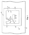
米国特許第5,612,524号、米国特許第4,972,475号、及び米国特許第4,924,078号に記述されているように、エリアシンボロジー(area symbology)は周知である。これらの米国特許の全ての開示内容は、本明細書中で引用されることにより、あらゆる意味において、本明細書に組み込まれている。このようなエリアシンボロジーの代表的なシンボル10が図1に示されている。一般に、シンボル10は、マトリックスとして配列された内部データセル14を有する内部データフィールド12を含む。この内部データフィールド12及び内部データセル14は、好ましくは、図示のように矩形であるが、任意のその他の形状も考えられる。図示のように、内部データフィールド12は、「オン(ON)」である特定のデータセル14と、「オフ(OFF)」である特定のデータセル14とを有する。図示のように、「オン」のデータセルは、黒色であり(参照符号16、18、20、及び22によって示されたセル)、「オフ」のデータセルは、白色である(内部データフィールド12の残りのセル)。このようなオン及びオフの指定は、シンボル10等のシンボルをデコードする際に使用される。データセル14を区別するために、オン及びオフ、0及び1、並びに、黒色及び白色を含む任意のバイナリ指定を使用することが可能であることを理解されたい。
Area symbology is well known, as described in US Pat. No. 5,612,524, US Pat. No. 4,972,475, and US Pat. No. 4,924,078. The entire disclosure of these U.S. patents is hereby incorporated herein in its entirety by reference. A
図示のように、内部データフィールド12は、好ましくは、方向付け及び/又はタイミングデータセル境界24によって取り囲まれている。このデータセル境界24は、通常、タイミング及びシンボルの方向付けのために使用される。データセル境界は、通常、図示のように、「オン」のデータセルから形成される。データセル境界24を取り囲む外部データフィールド26を提供することが可能である。この外部データフィールド26は、方向付け、タイミング、又はシンボルの識別に関する追加情報を提供する外部データセル(図示されてはいない)を包含することが可能である。好ましくは、データセル境界24を取り囲んでいるもの、即ち、外部データフィールド26は、提供されている場合には、「オン」のデータセルの最も外側のパターンを取り囲む「オフ」のデータセルの1つ又は複数の同心円状の直線的なリングと等価であるようなクワイエットゾーンである。このクワイエットゾーンの同心円状の直線的なリングの必要数は、シンボル使用法の環境的な要因によって決定されることが可能である。或いは、この代わりに、外部データフィールド26は、クワイエットゾーンとして機能することも可能であり、又は更なるクワイエットゾーンによって取り囲むことも可能である。
As shown, the
シンボル10は、インク又はその他のコーティングの印刷又は制御された蒸着等によって基板28上に直接的に形成することも可能であり、或いは、印刷又は任意のその他の適切な手法により、ステッカー又はラベル上に形成した後に、基板に接着又はその他の方法で装着することも可能である。
The
本発明の原理は、任意のリニア型のエリア又は積層型のエリア又はその他のシンボロジーからの任意のシンボル、並びに、好ましくは、後述するように、エリアリリーフパターンとして形成されたシンボルに対して適用可能である。本明細書に使用されているエリアシンボロジーとは、バー及びスペースの1つ又は複数の列ではなく、データセルのマトリックスを利用しているVericode(登録商標)又はData Matrix(登録商標)又はCode One(登録商標)又はこれらに類似したもの等の登録商標名の下に商業的に知られているものであるような任意のシンボロジーを意味している。本明細書に使用されている積層型のシンボロジーとは、複数幅のバー及びスペースのグループにより規定されたいくつかの文字を各々の列が有するようなシンボルのいくつかの隣接する列を一般に利用しているPDF 417等の任意のシンボロジーを意味している。 The principles of the present invention can be applied to any linear area or stacked area or any symbol from other symbologies, and preferably symbols formed as area relief patterns, as described below. It is. As used herein, area symbology refers to Vericode® or Data Matrix® or Code that utilizes a matrix of data cells rather than one or more columns of bars and spaces. Any symbology that is commercially known under the registered trade name, such as One® or similar, is meant. As used herein, stacked symbology generally utilizes several adjacent columns of symbols, each column having several characters defined by a group of multi-width bars and spaces. Meaning any symbology such as PDF 417.
本明細書に使用されているシンボルとは、一般的に、セルの特徴及び組織の内部にエンコードされたデータを含むセルのマトリックスを意味している。マトリックスとは、組織化されたセルのパターンである。セルとは、エンコードされたデータを保持する特徴を有するマトリックス内の単一の構成要素である。上記の特徴は、色、グレースケール、形状、パターン、又は特殊な光学インク等のセル構造に対して適用された様々な属性又は要素を有する。好ましくは、上記の特徴は、別個のエンティティとしてソフトウェアアルゴリズム内において規定することが可能であり、別個のエンティティとしてデジタルカラープリンタによって印刷可能であり、且つ/又は、カラーデジタルカメラによって画像を生成することにより、別個のエンティティとして出力可能である。 As used herein, a symbol generally refers to a matrix of cells containing cell characteristics and data encoded within the organization. A matrix is an organized pattern of cells. A cell is a single component in a matrix that has the characteristics of holding encoded data. The above features have various attributes or elements applied to the cell structure such as color, gray scale, shape, pattern, or special optical ink. Preferably, the above features can be defined in the software algorithm as a separate entity, printable by a digital color printer as a separate entity, and / or generate an image by a color digital camera. Can be output as a separate entity.
本発明に係るコード及びシンボルは、データコンテンツを増大させるのみならず、多数の新しいエンコーディング法及びデコーディング法の実施を可能にしてセキュリティを追加し、セルシンボル又はコード内におけるデータの補正を強化し、任意の種に関して所定の特徴を有するタイプ及び要素の既知の配置によって可読性を向上させ、且つ、2ビットセルによっては可能ではなかった数え切れないほどのその他の改善を実現する。 The codes and symbols according to the present invention not only increase data content, but also enable the implementation of a number of new encoding and decoding methods to add security and enhance the correction of data within cell symbols or codes. Improve readability with known arrangements of types and elements having predetermined characteristics with respect to any species, and realize countless other improvements not possible with 2-bit cells.
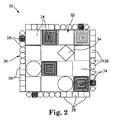
図2を参照すれば、本発明による例示用の多次元シンボル(多次元マトリックスシンボル)30が概略的に示されている。多次元シンボル30は、データセル34のマトリックスを有する内部データフィールド32と、データセル38からなる方向付け及び/又はタイミングデータセル境界36とを有する。
Referring to FIG. 2, an exemplary multidimensional symbol (multidimensional matrix symbol) 30 according to the present invention is schematically illustrated. The
図示のように、内部データフィールド32のデータセル34は、多次元データセルを有するが、(例えば、黒色及び白色等の)バイナリデータセルを有することも可能である。又、図示のように、データセル境界36のデータセル38は、多次元データセルを有するが、必要に応じて、バイナリデータセルを有することも可能である。本明細書に使用されている多次元データセルとは、各々がデータビットを表しており、且つ、2つを上回る数のデータビットのデータによってエンコードされた複数の特有の特徴を有するデータセルを意味している。
As shown, the
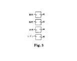
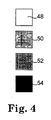
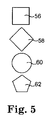
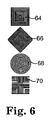
本発明に係る多次元データセルと共に使用可能である例示用の特有の特徴が図3〜図6に示されている。これらの特有の特徴は、色、グレースケールレベル、形状、及び幾何学的なデザインを含む。図3には、例示用のデータセル40、42、44、及び46が示されている。本発明によれば、データセル40、42、44、及び46は、それぞれ、例示用の色の特有の特徴を示している。データセル40、42、44、及び46は、正方形として示されているが(本発明による別の特有の特徴)、任意の所望の形状又は1つ又は複数の追加の特有の特徴を有することが可能である。本発明の一実施態様によれば、データセル40は、黄色であり、データセル42は、緑色であり、データセル44は、赤色であり、且つ、データセル46は、シアンであるが、任意の所望の色を使用することが可能である。図4には、例示用のデータセル48、50、52、及び54が示されている。本発明によれば、データセル48、50、52、及び54は、それぞれ、グレースケールの特有の特徴を示している。データセル48、50、52、及び54は、正方形として示されているが(本発明による別の特有の特徴)、任意の所望の形状又は1つ又は複数の追加の特有の特徴を有することが可能である。本発明の一実施態様によれば、データセル48は、白色であり、データセル54は、黒色であり、データセル50及び52は、白と黒との間のグレースケールを有する。図5には、例示用のデータセル56、58、60、及び62が示されている。本発明によれば、データセル56、58、60、及び62は、それぞれ、形状の特有の特徴を示している。データセル56、58、60、及び62は、白色として示されているが、任意の所望の色又は1つ又は複数の追加の特有の特徴を有することが可能である。本発明の一実施態様によれば、データセル56は、正方形であり、データセル58は、ダイアモンド形状であり、データセル60は、円形であり、且つ、データセル62は、五角形である(5辺を有する)。図6には、例示用のデータセル64、66、68、及び70が示されている。本発明によれば、データセル64、66、68、及び70は、それぞれ、幾何学的なパターンの特有の特徴を示している。データセル64、66、68、及び70は、様々な形状を有するものとして示されているが、任意の形状又は1つ又は複数の追加の特有の特徴を有することが可能である。本発明の一実施態様によれば、データセル64は、所定の間隔で配置されたラインの第1の幾何学的なパターンを有し、データセル66は、所定の間隔で配置されたラインの第2の幾何学的なパターンを有し、データセル68は、同心円の幾何学的なパターンを有し、データセル70は、所定の間隔で配置されたラインの第3の幾何学的なパターンを有する。
Illustrative specific features that can be used with multidimensional data cells according to the present invention are illustrated in FIGS. These unique features include color, gray scale level, shape, and geometric design.
本発明に係る多次元シンボルは、複数の特有の特徴の任意の組み合わせを有するデータセルを使用することが可能である。例えば、4つの異なる色、4つのグレースケールのレベル、4つの異なる形状、及び、4つの異なるパターンがデータセルに利用可能である場合には、データセルごとに利用可能なデータビットの数は、(例えば、黒色及び白色等の)バイナリセルにおける2ビットと比べて、1つのセル当たりに、4×4×4×4、即ち、256ビットのデータとなるであろう。 A multidimensional symbol according to the present invention can use data cells having any combination of a plurality of unique features. For example, if four different colors, four grayscale levels, four different shapes, and four different patterns are available for a data cell, the number of data bits available per data cell is There will be 4 × 4 × 4 × 4, or 256 bits of data per cell compared to 2 bits in a binary cell (eg, black and white).
本発明に係るデータのエンコーディングは、Vericode(登録商標)又はData Matrix(登録商標)又はCore One(登録商標)という登録商標名の下に商業的に知られているもの等の周知のエリアシンボロジーにおいて実行されているものと同様に実行可能である。データをエンコードするための代表的な方法は、2005年5月3日付けで出願された「情報をエンコードすると共にデコードする方法(Methods for Encoding and Deconding Information)」という名称の米国特許出願第11/121,762号に記述されており、この全ての開示内容は、本明細書中で引用されることにより、あらゆる意味において、本明細書に組み込まれている。通常、これらの手法においては、情報をリード−ソロモン(Reed−Solomon)ブロックにエンコードするステップを含む適切な方法によって情報をエンコードしている。エンコーディングの対象となるデータは、バイナリコードのストリングを形成するバイナリコードによって表されている。バイナリコードのストリングに基づいてCRC(Cyclical Redundancy Check:巡回冗長検査)と呼ばれる値を演算する。CRCは、バイナリストリングに付加される。CRCは、デコードされた情報が正しいことをチェックするために読み取り装置によって使用される。次いで、バイナリストリングに基づいて64ビットのリード−ソロモン(Reed−Solomon)ブロックコードを生成する。リード−ソロモン(Reed−Solomon)ブロックコードによれば、データのある部分が損傷した際にも、オリジナルのデータを復元することが可能である。リード−ソロモン(Reed−Solomon)ブロックコードは、シンボルのEDAC(Error Detection and Correction:エラー検出と訂正)機能の基礎である。ブロックコードからのビット値は、好ましくは、インターリーブされており、従って、ほこりや擦り傷等によって発生したシンボルに対する斑点状の損傷が様々なブロックに跨って分散される。この結果、シンボルが読み取り不能になる可能性が低くなる。次いで、エンコードされた情報から、複数のデータセルを含むデータマトリックスを生成する。次に、データマトリックスをシンボルの形態においてビットマップ画像に変換し、このビットマップ画像を物体、ラベル、ボックス等の上に印刷する。例えば、このタイプのシンボルは、いまや、在庫管理、POS(Point Of Sale:販売時点管理)識別、又は物流追跡システム等の様々な利用分野において一般的に使用されている。 The encoding of the data according to the present invention is well-known area symbology, such as those known commercially under the registered trademark names Vericode® or Data Matrix® or Core One®. It can be executed in the same manner as that executed in. An exemplary method for encoding data is US patent application Ser. No. 11/11, filed May 3, 2005, entitled “Methods for Encoding and Decoding Information”. No. 121,762, the entire disclosure of which is incorporated herein in its entirety by reference herein. Typically, in these approaches, the information is encoded by an appropriate method including the step of encoding the information into a Reed-Solomon block. The data to be encoded is represented by a binary code that forms a binary code string. A value called CRC (Cyclic Redundancy Check) is calculated based on the binary code string. The CRC is added to the binary string. The CRC is used by the reader to check that the decoded information is correct. A 64-bit Reed-Solomon block code is then generated based on the binary string. According to the Reed-Solomon block code, it is possible to restore the original data even when a part of the data is damaged. The Reed-Solomon block code is the basis of the symbol EDAC (Error Detection and Correction) function. The bit values from the block code are preferably interleaved, so that spotted damage to symbols caused by dust, scratches, etc. is distributed across the various blocks. As a result, the possibility that the symbol cannot be read is reduced. Then, a data matrix including a plurality of data cells is generated from the encoded information. Next, the data matrix is converted into a bitmap image in the form of a symbol, and the bitmap image is printed on an object, label, box, or the like. For example, this type of symbol is now commonly used in various applications such as inventory management, POS (Point of Sale) identification, or logistics tracking systems.
又、セルは、便宜上、グループとして組織化することも可能である。例えば、単一のコード内において2つの異なる組織を使用することが可能である。第1エリアは、シンボルの1つ又は複数のコーナーに位置し、これを記述子ブロックと呼ぶ。この記述子ブロックは、2×2のセルブロックから構築され、且つ、合計で71ビットのデータ用に3×3ブロックとして組織化される。このフィールドは、X軸及びY軸内のセルの数、CRCの数値、又は、コードに使用される暗号化キーのアイデンティティ等のコードに関する情報を収容することが可能である。データセルは、3×3のセルブロックとして組織化される。データブロックの合計数は、X軸およびY軸内のセルの数を乗算したものを9によって除算し、且つ、1つ又は複数の記述子ブロックについて4又は16を減算することによって算出することが可能である。合計数には、記述子ブロック及びデータブロックが含まれていることに留意されたい。X軸セル及びY軸セルは、いずれも、好ましくは、3によって割り切れるものである。 Cells can also be organized as a group for convenience. For example, it is possible to use two different organizations within a single code. The first area is located at one or more corners of the symbol and is called a descriptor block. This descriptor block is constructed from 2 × 2 cell blocks and organized as a 3 × 3 block for a total of 71 bits of data. This field may contain information about the code, such as the number of cells in the X and Y axes, the numeric value of the CRC, or the identity of the encryption key used for the code. Data cells are organized as 3 × 3 cell blocks. The total number of data blocks can be calculated by multiplying the number of cells in the X and Y axes by 9 and subtracting 4 or 16 for one or more descriptor blocks. Is possible. Note that the total number includes descriptor blocks and data blocks. Both the X-axis cell and the Y-axis cell are preferably divisible by 3.
本発明に係るシンボルは、任意の適切な印刷又は画像形成法によって生成されることが可能である。好ましくは、一例として色を使用することにより、各々のセルは、恐らくは、赤色、緑色、及び青色(RGB)成分としてソフトウェアにおいて規定され得る色を有するが、シアン、マゼンタ、黄色、及び黒色(CMYK)成分によって規定され得ると共にカラーデジタルプリンタ又はこれに類似したものに送付可能である形態にすることも可能であろう。好ましくは、プリンタは、マトリックス内において使用される全ての残りの色とは別個の色として認識することができるように、その色の組み合わせを印刷する能力を有する。スポットが相対的に大きいと共に互いにちょうど重畳するレーザープリンタと比べて、インクジェットプリンタの場合には、原色の滴が非常に小さく、且つ、一緒に放出されて、識別可能な色の更に多くの組み合わせを提供する。本発明に従って、グレースケール、形状、及び幾何学的なパターンについて、類似の技術を使用することが可能である。 The symbols according to the present invention can be generated by any suitable printing or imaging method. Preferably, by using color as an example, each cell has a color that can possibly be defined in software as a red, green, and blue (RGB) component, but cyan, magenta, yellow, and black (CMYK). It could also be in a form that can be defined by components and can be sent to a color digital printer or the like. Preferably, the printer has the ability to print that color combination so that it can be recognized as a color distinct from all the remaining colors used in the matrix. Compared to laser printers where the spots are relatively large and just overlap each other, in the case of inkjet printers, the primary color drops are very small and are ejected together to give more combinations of distinguishable colors. provide. In accordance with the present invention, it is possible to use similar techniques for grayscale, shape, and geometric patterns.
コードを印刷する際の別の機能は、透明色の積層化によって全ての特徴が観察可能となるプロセスカラーの使用である。レーザー及びインクジェット等の大部分の一般的なプリンタのタイプは、透明色を使用している。 Another function when printing codes is the use of process colors, where all features can be observed by layering transparent colors. Most common printer types such as lasers and ink jets use transparent colors.
本発明に従ってシンボルを読み取るためには、視野内においてシンボルを検出し、4つのコーナーを識別して回転及びスキューを判定し、矩形になるようにマトリックスを調節して戻すか、或いは、(水平セル及び垂直セルの数に基づいて)回転及びスキューについて調節された水平ライン及びセルと垂直ライン及びセルを配置すべき各々のラインの対の交点を少なくともセットアップ(set up)する。 To read a symbol in accordance with the present invention, the symbol is detected in the field of view, the four corners are identified to determine rotation and skew, and the matrix is adjusted back to a rectangle, or (horizontal cell And at least set up the intersections of the horizontal lines and the vertical lines and each line pair where the cells are to be placed, adjusted for rotation and skew (based on the number of vertical cells).
通常、このような分析は、最も中心のピクセルであると考えられるものから始まり、且つ、中心から離れる方向にピクセルが移動する間に平均化される乗数の値を低減させることにより、外側に移動するピクセルに対して重みを付与する。色が平均値から離れ過ぎているピクセルが識別された際には、当該ピクセルを拒絶し、平均化しない。マトリックス又は拒絶されたピクセルによって予め定められた限度に到達したときに、その平均値が、その色及びグレースケールの成分である。形状は、パターンに基づいて形状を探すことにより、拒絶されたピクセルとの比較においてカラーピクセルを観察することによって判定される。セル内のパターンは、中心から放射状に広がる円であってよく、中心から放射状に広がる正方形であってよく、中心から放射状に広がる三角形であってよく、且つ、マトリックスからのデータに対して変換が適用された際に異なるシグニチャ(signature)を提供するその他の幾何学的な構成であってよいであろう。 Typically, such an analysis starts with what is considered to be the most central pixel and moves outward by reducing the multiplier value that is averaged as the pixel moves away from the center. A weight is assigned to the pixel to be processed. When a pixel whose color is too far from the average is identified, it is rejected and not averaged. When a predetermined limit is reached by the matrix or rejected pixels, the average value is the color and grayscale component. The shape is determined by observing the color pixel in comparison with the rejected pixel by looking for the shape based on the pattern. The pattern in the cell may be a circle radiating from the center, a square radiating from the center, a triangle radiating from the center, and transforming data from the matrix. There could be other geometric configurations that provide different signatures when applied.
一般的な印刷コード及びカメラは、コード又はカメラ間において、且つ、時間の経過と共に変化する。従って、シンボルを読み取る瞬間において各々の特徴を認識するべくカメラを調節する方法が、本発明に従って提供される。好ましくは、正しいデータがマトリックス内の各々の特徴について出力されるように、境界を(好ましくは、マトリックス内のセルよりも大きい)セルの既知のアレイとしてセットアップすることにより、ソフトウェアアルゴリズムを再較正するための各々の特徴の一例をコード読み取りソフトウェアに提供する。境界は、追加の特徴を使用して、回転及びスキューの判定を向上させることも可能である。例えば、各々の原色及び黒色の大きなセルを4つのコーナーに配置することが可能である。大きなセルのパターンは、方向付けを識別し、大きなセルの正確な形状は、スキューのインジケータとなる。4つのコーナーのセルの形状データが、アライメント(alignment)が判定される既知の場所にそれぞれ位置している複数の境界セルからのデータに追加され、且つ、4つのコーナーの観察から判明したスキューに追加された場合には、このようにして組み合わせられた情報は、シンボルの4つの辺の中央が外側に向かって丸くなるレンズのバレリング(barreling)、及び、コーナーポイント自体の観察によっては発見及び補正されない状態でレンズがシンボルと正対していないことに起因して発生する台形問題(trapezoidal problem)のような不均衡なスキューに関する更に正確な実態を提供する。又、境界上の既知の1つ又は複数の場所における1つ又は複数の可変セルは、各々の軸上のセルの数、記述子ブロックを検出する場所、暗号化コード、及びこれらに類似したもの等のシンボルに関する情報を有することも可能である。 Typical print codes and cameras vary between codes or cameras and over time. Thus, a method for adjusting the camera to recognize each feature at the moment of reading a symbol is provided according to the present invention. Preferably, the software algorithm is recalibrated by setting up the boundaries as a known array of cells (preferably larger than the cells in the matrix) so that the correct data is output for each feature in the matrix. An example of each feature for providing code reading software is provided. Boundaries can also use additional features to improve rotation and skew determination. For example, each primary and black large cell can be placed in four corners. The large cell pattern identifies the orientation and the exact shape of the large cell is an indicator of skew. The shape data of the cells at the four corners is added to the data from a plurality of boundary cells respectively located at known locations where the alignment is determined, and the skew determined from the observation of the four corners. When added, the combined information is found and corrected by lens barreling, where the center of the four sides of the symbol is rounded outward, and by observation of the corner points themselves. It provides a more accurate picture of the unbalanced skew, such as trapezoidal problems that occur due to the lens not facing the symbol in the unsettled state. Also, one or more variable cells at one or more known locations on the boundary are the number of cells on each axis, the location to detect the descriptor block, the encryption code, and the like It is also possible to have information about symbols such as.
従来のエリアアレイカメラは、黒色又は白色という単一の特徴を上回るものを弁別するために利用可能である固有の機能を有する。一般的なカメラは、各々の要素ごとに24ビットの情報を出力する。通常、8ビットは、要素のグレースケールのために使用されており、残りの16ビットが、赤色、緑色、及び青色(RGB)という3つの原色、又はシアン、マゼンタ、黄色、(及び黒色)(CMYK)という補色の間において分割されている。本発明の一実施態様は、単一のセルから積層化された情報を抽出することができるようにする1つ又はいくつかの異なる方法又は設計を使用するステップを含む。既知の方法は、各々の要素からの2ビットのデータビット(黒色又は白色)のみを使用しており、通常、24ビット、又は、最大で4色又は8色のなんらかのサブセットが利用可能である。本発明に係るコードは、各々の要素からの2つを上回る数のデータビットを使用している。本発明に係るセルは、いくつかの色から構成されることが可能であり、これらの色は、原色及び透明な原色の組み合わせを使用するその他の色を包含することが可能である。セル内の各々の色は、グレースケールの特徴におけるグレースケール要素のレベル数の倍数だけ各々の色を区別するための変化するグレースケールのレベルを有することが可能である。各々のセルは、正方形、ダイアモンド、円、又はカメラ要素のアレイによって容易に弁別されるその他の形状等の異なる形状として設計可能である。セル内には、カメラ要素のアレイを使用した光学的分析において既知の変換によって分析された際に異なる応答を提供する様々なパターンを生成することが可能である。印刷されたコードの場合には、その他の特徴との差別化によって認識可能であるカメラ要素又はその他の装置からの応答を誘発させるために、色、グレースケール、形状、又はパターンと同様に、赤外線、UV、蛍光等のその他の特徴を有するインクを使用することが可能である。異なる特徴を有するシンボルセルを使用して、セル及びその正確な場所を更に正確に識別することが可能である。黒色セルは、コードエリア内の望ましくないアーチファクト(artifact)と同一色になる可能性があり(黒色及び白色という2色画像を仮定した場合)、且つ、良好なセル又は良好なセルの境界から弁別することが困難であるのに対して、有色のセルは、背景雑音に入ってしまう可能性が低い。
Conventional area array cameras have a unique function that can be used to discriminate more than a single feature of black or white. A
本発明の別の実施態様は、コードに使用された特徴の全てを各々のコード上の既知の場所に配置し、読み取り対象のコードについてカメラを再較正するというものである。特徴の冗長な配置は、較正の特徴のいくつかのものに対する損傷によって発生する問題を除去するのに有用であり、且つ、多くの入力に跨って較正を平均化するのにも有用である。又、コード内のタイミングマークは、セルの場所に関する追加情報を提供する異なる特徴から構成されることも可能であり、或いは、追加されたシンボルエンコーディング及びデコーディングのために使用されることも可能である。較正の特徴を、例えば、シンボルの4つの境界上に配置することにより、色値、グレースケール値、形状シグニチャ、変形シグニチャ、及び使用されるあらゆるその他の特徴を設定することが可能であり、且つ、それらが提供する値又はシグニチャを使用して、セル読み取り値を更に正確に較正することが可能である。又、特徴の4つの境界の分析は、匹敵する位置における既知の特徴間の違いを示し、これによって、匹敵するデータに基づいた回転、スキュー、及び照明の問題に対する補正を実現することが可能である。境界は、既知の場所に異なる要素を有することが可能であるため、視野内におけるコードの検出が更に正確且つ信頼性の高いものになる。異なる特徴を有するタイミングセルを使用し、タイミングマーク及びその正確な場所を更に正確に識別することが可能である。現在、黒色セルは、コードエリア内の望ましくないアーチファクトと同一の色であり(黒色及び白色という2色画像を仮定した場合)、且つ、良好なセルと弁別することが困難である。一例として、境界を取り上げれば、1つの境界上における特徴の積層化、コードの4つのコーナー上のボックス領域内における特徴の検出、並びに、本発明のこれらの実施態様による多数のその他の方法等の較正の特徴を検出するような多数の方式を利用することが可能であろう。 Another embodiment of the present invention is to place all of the features used in the code at known locations on each code and recalibrate the camera for the code to be read. Redundant placement of features is useful to eliminate problems caused by damage to some of the calibration features, and is also useful for averaging calibration across many inputs. The timing marks in the code can also consist of different features that provide additional information about the cell location, or can be used for additional symbol encoding and decoding. is there. By placing calibration features on, for example, the four boundaries of the symbol, it is possible to set color values, grayscale values, shape signatures, deformation signatures, and any other features used; and The values or signatures they provide can be used to more accurately calibrate cell readings. Analysis of the four boundaries of features also shows the differences between known features at comparable locations, which can provide corrections for rotation, skew, and lighting problems based on comparable data. is there. Since the boundary can have different elements at known locations, the detection of codes in the field of view is more accurate and reliable. Using timing cells with different characteristics, it is possible to more accurately identify the timing mark and its exact location. Currently, black cells are the same color as undesirable artifacts in the code area (assuming a two-color image of black and white) and are difficult to distinguish from good cells. As an example, taking a boundary, such as layering features on one boundary, detecting features in a box region on four corners of the code, and many other methods according to these embodiments of the present invention, etc. It would be possible to use a number of ways to detect calibration features.
本発明の別の特徴は、本発明の多次元シンボロジーコードを読み取ることが可能であるエリアアレイカメラの利用法である。使用されるカメラのハードウェアは、通常、現在市販されているCCD、COMS、又はその他の技術であってよいが、好ましくは、カメラ調節装置、ファームウェア、ソフトウェア、ドライバ、及びその他の制御方法は、望ましくは、本明細書に記述されている特徴の1つ又は複数のものを使用して本発明の多次元シンボロジーコードを読み取るべく最適化される。 Another feature of the present invention is the use of an area array camera capable of reading the multidimensional symbology code of the present invention. The camera hardware used may typically be CCD, COMS, or other technology currently on the market, but preferably the camera adjuster, firmware, software, driver, and other control methods are: Desirably, one or more of the features described herein are used to optimize the multidimensional symbology code of the present invention for reading.
以上、いくつかの実施例(実施形態)を参照し、本発明について説明した。本明細書において特定された特許又は特許出願の全ての開示内容は、本明細書中で引用されることにより、本明細書に組み込まれている。以上の詳細な説明及び例は、本発明をわかりやすくするために呈示されたものに過ぎない。これらの説明及び例は、限定を意図したものと理解してはならない。当業者には、本発明の範囲を逸脱することなしに、記述された実施例において多数の変更を実施することが可能であることが明らかであろう。従って、本発明の範囲は、本明細書に記述された構造に限定されるものではなく、特許請求の範囲の請求項に記述された構造又はそれらの構造の等価物によってのみ限定される。 The present invention has been described above with reference to several examples (embodiments). The entire disclosure of the patents or patent applications identified in this specification is hereby incorporated by reference herein. The foregoing detailed description and examples have been presented merely to facilitate understanding of the present invention. These descriptions and examples should not be construed as limiting. It will be apparent to those skilled in the art that many changes can be made in the embodiments described without departing from the scope of the invention. Accordingly, the scope of the invention is not limited to the structures described herein, but only by the structures described in the claims or the equivalents of those structures.
Claims (17)
少なくとも1つのデータセルは、複数の特有の特徴を有し、且つ、各々の特有の特徴は、エンコードされたデータビットを表すことを特徴とする多次元マトリックスシンボル。 In a multidimensional matrix symbol having a plurality of data cells,
A multidimensional matrix symbol, wherein at least one data cell has a plurality of unique features, and each unique feature represents an encoded data bit.
前記第2の複数のデータセルの中の少なくとも1つのデータセルは、複数の特有の特徴を有し、且つ、各々の特有の特徴は、エンコードされたデータビットを表すことを特徴とする多次元マトリックスシンボル。 In a multidimensional matrix symbol having an internal data field having a first plurality of data cells and a data cell boundary having a second plurality of data cells,
At least one data cell in the second plurality of data cells has a plurality of unique features, and each unique feature represents an encoded data bit Matrix symbol.
複数のデータセルを有する多次元マトリックスシンボルを提供するステップであって、少なくとも1つのデータセルは、複数の特有の特徴を有し、且つ、各々の特有の特徴は、エンコードされたデータビットを表すステップと、
各々の前記データセルにおける各々の特有の特徴を識別するステップと、
各々の特有の特徴によって表されるデータをデコードするステップとを有することを特徴とする方法。 In a method for reading a multidimensional matrix symbol,
Providing a multidimensional matrix symbol having a plurality of data cells, wherein at least one data cell has a plurality of unique features, and each unique feature represents an encoded data bit Steps,
Identifying each unique feature in each said data cell;
Decoding the data represented by each unique feature.
第1の複数のバイナリデータセルを有する内部データフィールドと、第2の複数の多次元データセルを有するデータセル境界とを有する多次元マトリックスシンボルを提供するステップであって、前記第2の複数の多次元データセルの中の少なくとも1つの多次元データセルは、複数の特有の特徴を有し、且つ、各々の特有の特徴は、エンコードされたデータビットを表すステップと、
前記第1の複数のバイナリデータセルによって表されるデータをデコードするステップと、
前記第2の複数の多次元データセルの各々の多次元データセルにおける各々の特有の特徴を識別するステップと、
各々の特有の特徴によって表されるデータをデコードするステップとを有することを特徴とする方法。 In a method for reading a multidimensional matrix symbol,
Providing a multidimensional matrix symbol having an internal data field having a first plurality of binary data cells and a data cell boundary having a second plurality of multidimensional data cells, wherein the second plurality At least one multidimensional data cell in the multidimensional data cell has a plurality of unique features, and each unique feature represents an encoded data bit;
Decoding data represented by the first plurality of binary data cells;
Identifying each characteristic feature in each multidimensional data cell of each of the second plurality of multidimensional data cells;
Decoding the data represented by each unique feature.
Applications Claiming Priority (2)
| Application Number | Priority Date | Filing Date | Title |
|---|---|---|---|
| US81376906P | 2006-06-14 | 2006-06-14 | |
| PCT/US2007/013815 WO2007146303A2 (en) | 2006-06-14 | 2007-06-13 | Multi-dimensional symbologies and related methods |
Publications (1)
| Publication Number | Publication Date |
|---|---|
| JP2009540468A true JP2009540468A (en) | 2009-11-19 |
Family
ID=38832496
Family Applications (1)
| Application Number | Title | Priority Date | Filing Date |
|---|---|---|---|
| JP2009515462A Pending JP2009540468A (en) | 2006-06-14 | 2007-06-13 | Multidimensional symbology and related methods |
Country Status (12)
| Country | Link |
|---|---|
| US (1) | US7510125B2 (en) |
| EP (1) | EP2027561A2 (en) |
| JP (1) | JP2009540468A (en) |
| KR (1) | KR20090018811A (en) |
| CN (1) | CN101467161A (en) |
| AU (1) | AU2007258332A1 (en) |
| CA (1) | CA2654085A1 (en) |
| MX (1) | MX2008015959A (en) |
| MY (1) | MY153301A (en) |
| RU (1) | RU2009100923A (en) |
| WO (1) | WO2007146303A2 (en) |
| ZA (1) | ZA200810452B (en) |
Cited By (8)
| Publication number | Priority date | Publication date | Assignee | Title |
|---|---|---|---|---|
| JP2011175314A (en) * | 2010-02-23 | 2011-09-08 | Fuji Xerox Co Ltd | Two-dimensional bar code reader, program, two-dimensional bar code, and medium |
| KR101241111B1 (en) | 2011-04-07 | 2013-03-11 | 주식회사 아이씨비에스 | Two-dimensional code incoding and decoding method |
| JP2013134775A (en) * | 2011-12-23 | 2013-07-08 | Konica Minolta Laboratory Usa Inc | Four-dimensional (4d) color bar code for encryption and decryption of large-volume data |
| JP5731059B1 (en) * | 2014-11-07 | 2015-06-10 | 共樹 阿南 | Virtual three-dimensional code and reading method thereof |
| US9269034B2 (en) | 2012-08-21 | 2016-02-23 | Empire Technology Development Llc | Orthogonal encoding for tags |
| JP2017079082A (en) * | 2011-08-16 | 2017-04-27 | モビリードMobilead | Optical-reading code preparation device |
| WO2019017433A1 (en) * | 2017-07-20 | 2019-01-24 | 株式会社デンソーウェーブ | Two-dimensional code and two-dimensional code reading device |
| JP2020173601A (en) * | 2019-04-10 | 2020-10-22 | ソノー電機工業株式会社 | Two-dimensional code, recognition processing program, recognition processing device, and recognition processing method |
Families Citing this family (26)
| Publication number | Priority date | Publication date | Assignee | Title |
|---|---|---|---|---|
| US20080067114A1 (en) * | 2006-09-18 | 2008-03-20 | Pitney Bowes Incorporated | Separator card for mailpiece handling equipment |
| US7874496B2 (en) * | 2008-01-04 | 2011-01-25 | Microsoft Corporation | Optically readable tag |
| MX2010008335A (en) * | 2008-01-29 | 2011-02-22 | Veritec Inc | Two-dimensional symbol and method for reading same. |
| US8011596B2 (en) * | 2008-02-13 | 2011-09-06 | Hand Held Products, Inc. | Machine readable 2D symbology printable on demand |
| JP5136302B2 (en) * | 2008-03-27 | 2013-02-06 | 株式会社デンソーウェーブ | Two-dimensional code, two-dimensional code generation method, computer-readable program for displaying two-dimensional code, authentication method using two-dimensional code, and information providing method using two-dimensional code |
| US20100084468A1 (en) * | 2008-10-02 | 2010-04-08 | Silverbrook Research Pty Ltd | Method of imaging coding pattern comprising columns and rows of coordinate data |
| CN102265292B (en) * | 2008-10-24 | 2014-06-11 | 惠普开发有限公司 | Security campaign and method of creating the same |
| CN102479336A (en) * | 2010-11-30 | 2012-05-30 | 上海航天精密机械研究所 | Multi-dimensional classification coding method for manufacturing information of aerospace product structural member |
| US8464343B1 (en) | 2010-12-30 | 2013-06-11 | Symantec Corporation | Systems and methods for providing security information about quick response codes |
| US8651389B2 (en) * | 2011-02-02 | 2014-02-18 | Infosys Limited | System and method for identifying and tracking shopping carts |
| US8490861B1 (en) * | 2011-03-10 | 2013-07-23 | Symantec Corporation | Systems and methods for providing security information about quick response codes |
| US8485428B1 (en) | 2011-03-10 | 2013-07-16 | Symantec Corporation | Systems and methods for providing security information about quick response codes |
| EP2754094A4 (en) * | 2011-09-08 | 2015-04-15 | Hewlett Packard Development Co | GENERATION OF AN INCRÉMENTAL INFORMATION OBJECT |
| US8915440B2 (en) * | 2011-12-23 | 2014-12-23 | Konica Minolta Laboratory U.S.A., Inc. | Four dimensional (4D) color barcode for high capacity data encoding and decoding |
| TWI463410B (en) * | 2012-08-10 | 2014-12-01 | Ind Tech Res Inst | Bar code structure and barcode encoding method |
| US10154177B2 (en) | 2012-10-04 | 2018-12-11 | Cognex Corporation | Symbology reader with multi-core processor |
| TWI554100B (en) * | 2012-12-27 | 2016-10-11 | Metal Ind Res &Development Ct | Correction sheet design for correcting a plurality of image capturing apparatuses and correction methods of a plurality of image capturing apparatuses |
| US9547924B2 (en) * | 2014-06-24 | 2017-01-17 | Raytheon Company | Composite launch acceptability region software |
| CN106683593A (en) | 2015-11-06 | 2017-05-17 | 沈维 | Billboard containing coding information |
| CN106934441B (en) * | 2017-03-26 | 2019-01-04 | 袁昕喆 | A kind of decoding method of multi-dimensional code |
| CA3076962A1 (en) * | 2017-09-26 | 2019-04-04 | Imprensa Nacional-Casa Da Moeda, Sa | Computational method and system for image generation with coded information, images obtained therefrom and reading method and system thereof |
| CN109325574B (en) * | 2018-09-21 | 2021-08-17 | 苏州玖典智能科技有限公司 | Colored two-dimensional code |
| CN109242078A (en) * | 2018-09-21 | 2019-01-18 | 苏州玖典智能科技有限公司 | A kind of color 2 D code |
| JP7754616B2 (en) * | 2020-03-31 | 2025-10-15 | 株式会社デンソーウェーブ | Information code reading system, information code reading device |
| JP6989859B2 (en) | 2020-04-10 | 2022-01-12 | 有限会社バラエティーエム・ワン | Information code, information code generator, information code reader, program and information code utilization system |
| JP7253749B2 (en) * | 2021-08-03 | 2023-04-07 | 学校法人立命館 | TWO-DIMENSIONAL CODE, GENERATOR, READER, AND COMPUTER PROGRAM |
Citations (11)
| Publication number | Priority date | Publication date | Assignee | Title |
|---|---|---|---|---|
| JPH0338791A (en) * | 1989-06-30 | 1991-02-19 | Veritel Inc | Symbol for confirmation and confirmation device thereof |
| JPH05225408A (en) * | 1992-02-14 | 1993-09-03 | Hisashi Ogawa | Signal area radiant division circle code |
| JPH08263580A (en) * | 1995-03-20 | 1996-10-11 | Y E Data Inc | Identification code mark |
| US5568555A (en) * | 1992-02-12 | 1996-10-22 | Colorcode Unlimited, Inc. | Multi-color information encoding system |
| US5612524A (en) * | 1987-11-25 | 1997-03-18 | Veritec Inc. | Identification symbol system and method with orientation mechanism |
| JPH0991395A (en) * | 1996-02-27 | 1997-04-04 | Teiriyou Sangyo Kk | Identification code paper |
| JPH10228526A (en) * | 1997-02-14 | 1998-08-25 | Takashi Sawaguchi | Display method for stereoscopic code |
| JPH10283446A (en) * | 1997-04-08 | 1998-10-23 | Nippon I D Tec Kk | Multicolor recording type matrix code recording sheet |
| JP2003178277A (en) * | 2001-12-11 | 2003-06-27 | Ricoh Co Ltd | Two-dimensional code, method for creating two-dimensional code, method for decoding two-dimensional code, apparatus for executing the method, program for executing the method on a computer, and computer-readable recording medium storing the program |
| JP2007065872A (en) * | 2005-08-30 | 2007-03-15 | Seiko Epson Corp | Information recording apparatus, printing apparatus, information recording method, and printing method |
| JP2007179134A (en) * | 2005-12-27 | 2007-07-12 | Dainippon Printing Co Ltd | Two-dimensional code, two-dimensional code reading method, and two-dimensional code reading apparatus |
Family Cites Families (6)
| Publication number | Priority date | Publication date | Assignee | Title |
|---|---|---|---|---|
| US2612994A (en) * | 1949-10-20 | 1952-10-07 | Norman J Woodland | Classifying apparatus and method |
| US4972475A (en) * | 1987-02-10 | 1990-11-20 | Veritec Inc. | Authenticating pseudo-random code and apparatus |
| US5331176A (en) * | 1992-04-10 | 1994-07-19 | Veritec Inc. | Hand held two dimensional symbol reader with a symbol illumination window |
| CA2285626A1 (en) * | 1997-04-08 | 1998-10-15 | Zebra Technologies Corporation | Distortion resistant double-data correcting color transition barcode and method of generating and using same |
| WO2005109327A2 (en) * | 2004-05-03 | 2005-11-17 | Veritec, Inc. | Methods for encoding and decoding information |
| US20060180672A1 (en) * | 2005-02-11 | 2006-08-17 | Chu Lonny L | Method and system for multi-dimensional symbol coding system |
-
2007
- 2007-06-13 US US11/818,112 patent/US7510125B2/en active Active
- 2007-06-13 CN CNA2007800220349A patent/CN101467161A/en active Pending
- 2007-06-13 JP JP2009515462A patent/JP2009540468A/en active Pending
- 2007-06-13 WO PCT/US2007/013815 patent/WO2007146303A2/en not_active Ceased
- 2007-06-13 KR KR1020087030029A patent/KR20090018811A/en not_active Ceased
- 2007-06-13 MX MX2008015959A patent/MX2008015959A/en not_active Application Discontinuation
- 2007-06-13 EP EP07809496A patent/EP2027561A2/en not_active Withdrawn
- 2007-06-13 CA CA002654085A patent/CA2654085A1/en not_active Abandoned
- 2007-06-13 AU AU2007258332A patent/AU2007258332A1/en not_active Abandoned
- 2007-06-13 MY MYPI20084863A patent/MY153301A/en unknown
- 2007-06-13 RU RU2009100923/08A patent/RU2009100923A/en not_active Application Discontinuation
-
2008
- 2008-12-10 ZA ZA200810452A patent/ZA200810452B/en unknown
Patent Citations (11)
| Publication number | Priority date | Publication date | Assignee | Title |
|---|---|---|---|---|
| US5612524A (en) * | 1987-11-25 | 1997-03-18 | Veritec Inc. | Identification symbol system and method with orientation mechanism |
| JPH0338791A (en) * | 1989-06-30 | 1991-02-19 | Veritel Inc | Symbol for confirmation and confirmation device thereof |
| US5568555A (en) * | 1992-02-12 | 1996-10-22 | Colorcode Unlimited, Inc. | Multi-color information encoding system |
| JPH05225408A (en) * | 1992-02-14 | 1993-09-03 | Hisashi Ogawa | Signal area radiant division circle code |
| JPH08263580A (en) * | 1995-03-20 | 1996-10-11 | Y E Data Inc | Identification code mark |
| JPH0991395A (en) * | 1996-02-27 | 1997-04-04 | Teiriyou Sangyo Kk | Identification code paper |
| JPH10228526A (en) * | 1997-02-14 | 1998-08-25 | Takashi Sawaguchi | Display method for stereoscopic code |
| JPH10283446A (en) * | 1997-04-08 | 1998-10-23 | Nippon I D Tec Kk | Multicolor recording type matrix code recording sheet |
| JP2003178277A (en) * | 2001-12-11 | 2003-06-27 | Ricoh Co Ltd | Two-dimensional code, method for creating two-dimensional code, method for decoding two-dimensional code, apparatus for executing the method, program for executing the method on a computer, and computer-readable recording medium storing the program |
| JP2007065872A (en) * | 2005-08-30 | 2007-03-15 | Seiko Epson Corp | Information recording apparatus, printing apparatus, information recording method, and printing method |
| JP2007179134A (en) * | 2005-12-27 | 2007-07-12 | Dainippon Printing Co Ltd | Two-dimensional code, two-dimensional code reading method, and two-dimensional code reading apparatus |
Cited By (9)
| Publication number | Priority date | Publication date | Assignee | Title |
|---|---|---|---|---|
| JP2011175314A (en) * | 2010-02-23 | 2011-09-08 | Fuji Xerox Co Ltd | Two-dimensional bar code reader, program, two-dimensional bar code, and medium |
| KR101241111B1 (en) | 2011-04-07 | 2013-03-11 | 주식회사 아이씨비에스 | Two-dimensional code incoding and decoding method |
| JP2017079082A (en) * | 2011-08-16 | 2017-04-27 | モビリードMobilead | Optical-reading code preparation device |
| JP2013134775A (en) * | 2011-12-23 | 2013-07-08 | Konica Minolta Laboratory Usa Inc | Four-dimensional (4d) color bar code for encryption and decryption of large-volume data |
| US9269034B2 (en) | 2012-08-21 | 2016-02-23 | Empire Technology Development Llc | Orthogonal encoding for tags |
| JP5731059B1 (en) * | 2014-11-07 | 2015-06-10 | 共樹 阿南 | Virtual three-dimensional code and reading method thereof |
| WO2019017433A1 (en) * | 2017-07-20 | 2019-01-24 | 株式会社デンソーウェーブ | Two-dimensional code and two-dimensional code reading device |
| JP2019021165A (en) * | 2017-07-20 | 2019-02-07 | 株式会社デンソーウェーブ | Two-dimensional code and two-dimensional code reader |
| JP2020173601A (en) * | 2019-04-10 | 2020-10-22 | ソノー電機工業株式会社 | Two-dimensional code, recognition processing program, recognition processing device, and recognition processing method |
Also Published As
| Publication number | Publication date |
|---|---|
| MX2008015959A (en) | 2009-03-02 |
| AU2007258332A8 (en) | 2009-01-08 |
| ZA200810452B (en) | 2009-11-25 |
| US7510125B2 (en) | 2009-03-31 |
| CA2654085A1 (en) | 2007-12-21 |
| US20080035730A1 (en) | 2008-02-14 |
| CN101467161A (en) | 2009-06-24 |
| AU2007258332A1 (en) | 2007-12-21 |
| WO2007146303A3 (en) | 2008-08-14 |
| RU2009100923A (en) | 2010-07-20 |
| KR20090018811A (en) | 2009-02-23 |
| WO2007146303A2 (en) | 2007-12-21 |
| EP2027561A2 (en) | 2009-02-25 |
| MY153301A (en) | 2015-01-29 |
Similar Documents
| Publication | Publication Date | Title |
|---|---|---|
| US7510125B2 (en) | Multi-dimensional symbologies and related methods | |
| JP5216764B2 (en) | Bar code authentication | |
| EP1612724B1 (en) | System and method for encoding high density geometric symbol set | |
| US7198194B2 (en) | Two-dimensional code having superior decoding properties making it possible to control the level of error correcting codes, and a method for encoding and decoding the same | |
| EP2122534B1 (en) | Multiple resolution readable color array | |
| CN113887689B (en) | Method and system for printing forensic encoded 2D bar codes | |
| GB2446424A (en) | Two dimensional bar code with locating symbols | |
| JP2013537990A (en) | Two-dimensional identification pattern, article containing the pattern, and method for marking and identifying the pattern | |
| EP1869624B1 (en) | A secure printing method to thwart counterfeiting | |
| WO2005086076A1 (en) | System for encoding information using colors | |
| US20140363081A1 (en) | Machine reading of printed data | |
| EP4453783B1 (en) | Two-dimensional barcode, method and system for encoding data into said two-dimensional barcode, and method and system for imaging and decoding said two-dimensional barcode | |
| WO2003012727A1 (en) | Data endocing and decoding using angular symbology | |
| CN102806788B (en) | A kind of method printing special-shaped matrix two-dimensional barcode on multiple part bills | |
| US8955760B2 (en) | Code pattern for providing information and decoding method and image processing device | |
| WO2012035552A2 (en) | Generating a code system using haar wavelets | |
| JP6420840B2 (en) | Simple encoding, authentication and copy detection system for printed documents | |
| Simske et al. | Revenge of the physical-mobile color barcode solutions to security challenges | |
| US20250335730A1 (en) | Method of Dynamically Encoding Information and Applying a Code to a Material and a Method of Decoding the Information | |
| AU2000253747B2 (en) | Data package template with data embedding | |
| Akila et al. | Secured data encoding technique in high capacity color barcodes for m-ticket application |
Legal Events
| Date | Code | Title | Description |
|---|---|---|---|
| A621 | Written request for application examination |
Free format text: JAPANESE INTERMEDIATE CODE: A621 Effective date: 20100611 |
|
| A977 | Report on retrieval |
Free format text: JAPANESE INTERMEDIATE CODE: A971007 Effective date: 20120411 |
|
| A131 | Notification of reasons for refusal |
Free format text: JAPANESE INTERMEDIATE CODE: A131 Effective date: 20120417 |
|
| A601 | Written request for extension of time |
Free format text: JAPANESE INTERMEDIATE CODE: A601 Effective date: 20120713 |
|
| A602 | Written permission of extension of time |
Free format text: JAPANESE INTERMEDIATE CODE: A602 Effective date: 20120723 |
|
| A521 | Request for written amendment filed |
Free format text: JAPANESE INTERMEDIATE CODE: A523 Effective date: 20121017 |
|
| A131 | Notification of reasons for refusal |
Free format text: JAPANESE INTERMEDIATE CODE: A131 Effective date: 20121204 |
|
| A601 | Written request for extension of time |
Free format text: JAPANESE INTERMEDIATE CODE: A601 Effective date: 20130301 |
|
| A602 | Written permission of extension of time |
Free format text: JAPANESE INTERMEDIATE CODE: A602 Effective date: 20130308 |
|
| A02 | Decision of refusal |
Free format text: JAPANESE INTERMEDIATE CODE: A02 Effective date: 20130730 |