JP2009537403A - Two-way valve body - Google Patents
Two-way valve body Download PDFInfo
- Publication number
- JP2009537403A JP2009537403A JP2009510458A JP2009510458A JP2009537403A JP 2009537403 A JP2009537403 A JP 2009537403A JP 2009510458 A JP2009510458 A JP 2009510458A JP 2009510458 A JP2009510458 A JP 2009510458A JP 2009537403 A JP2009537403 A JP 2009537403A
- Authority
- JP
- Japan
- Prior art keywords
- valve body
- pouch
- flow path
- stem
- outside
- Prior art date
- Legal status (The legal status is an assumption and is not a legal conclusion. Google has not performed a legal analysis and makes no representation as to the accuracy of the status listed.)
- Pending
Links
Images


Classifications
-
- B—PERFORMING OPERATIONS; TRANSPORTING
- B65—CONVEYING; PACKING; STORING; HANDLING THIN OR FILAMENTARY MATERIAL
- B65D—CONTAINERS FOR STORAGE OR TRANSPORT OF ARTICLES OR MATERIALS, e.g. BAGS, BARRELS, BOTTLES, BOXES, CANS, CARTONS, CRATES, DRUMS, JARS, TANKS, HOPPERS, FORWARDING CONTAINERS; ACCESSORIES, CLOSURES, OR FITTINGS THEREFOR; PACKAGING ELEMENTS; PACKAGES
- B65D83/00—Containers or packages with special means for dispensing contents
- B65D83/14—Containers or packages with special means for dispensing contents for delivery of liquid or semi-liquid contents by internal gaseous pressure, i.e. aerosol containers comprising propellant for a product delivered by a propellant
- B65D83/68—Dispensing two or more contents, e.g. sequential dispensing or simultaneous dispensing of two or more products without mixing them
- B65D83/682—Dispensing two or more contents, e.g. sequential dispensing or simultaneous dispensing of two or more products without mixing them the products being first separated, but finally mixed, e.g. in a dispensing head
-
- B—PERFORMING OPERATIONS; TRANSPORTING
- B65—CONVEYING; PACKING; STORING; HANDLING THIN OR FILAMENTARY MATERIAL
- B65D—CONTAINERS FOR STORAGE OR TRANSPORT OF ARTICLES OR MATERIALS, e.g. BAGS, BARRELS, BOTTLES, BOXES, CANS, CARTONS, CRATES, DRUMS, JARS, TANKS, HOPPERS, FORWARDING CONTAINERS; ACCESSORIES, CLOSURES, OR FITTINGS THEREFOR; PACKAGING ELEMENTS; PACKAGES
- B65D83/00—Containers or packages with special means for dispensing contents
- B65D83/14—Containers or packages with special means for dispensing contents for delivery of liquid or semi-liquid contents by internal gaseous pressure, i.e. aerosol containers comprising propellant for a product delivered by a propellant
- B65D83/42—Filling or charging means
- B65D83/425—Delivery valves permitting filling or charging
-
- B—PERFORMING OPERATIONS; TRANSPORTING
- B65—CONVEYING; PACKING; STORING; HANDLING THIN OR FILAMENTARY MATERIAL
- B65D—CONTAINERS FOR STORAGE OR TRANSPORT OF ARTICLES OR MATERIALS, e.g. BAGS, BARRELS, BOTTLES, BOXES, CANS, CARTONS, CRATES, DRUMS, JARS, TANKS, HOPPERS, FORWARDING CONTAINERS; ACCESSORIES, CLOSURES, OR FITTINGS THEREFOR; PACKAGING ELEMENTS; PACKAGES
- B65D83/00—Containers or packages with special means for dispensing contents
- B65D83/14—Containers or packages with special means for dispensing contents for delivery of liquid or semi-liquid contents by internal gaseous pressure, i.e. aerosol containers comprising propellant for a product delivered by a propellant
- B65D83/60—Contents and propellant separated
- B65D83/62—Contents and propellant separated by membrane, bag, or the like
Abstract
発明は、第一の可撓性パウチ内に封じ込めなければならない第一の流体と、流体が弁体を通って出るに第一の流体から隔離されるフラスコ内の第二の流体の、駆動手段を用いて硬質フラスコ内に封入された2つの流体を分配するための弁体において、弁体がフラスコの上に配置されたときに、前記フラスコ内部に位置づけられる内側部分と、弁体が前記フラスコ上に置かれたときに、フラスコ外部に位置づけられる外側部分と、第一の閉止手段を備えた、第一のパウチの内部と弁体の外側部分を囲繞する空間を接続する第一の流路と、第二の閉止手段を備えた、第二の流体を受けるための空間と弁体の外側部分を囲繞する空間を接続する第二の流路とから成る弁体を開示する。本発明の弁体は、弁体に固定された第二の流体を受けるための第二の可撓性パウチであって、第一のパウチの周囲に配置される第二のパウチによって先行技術のから区別される特徴を有する。
The invention provides a drive means for a first fluid that must be enclosed in a first flexible pouch and a second fluid in the flask that is isolated from the first fluid as it exits the valve body. A valve body for distributing two fluids enclosed in a rigid flask using an inner portion positioned inside the flask when the valve body is placed on the flask, and a valve body is the flask. A first flow path that connects the space surrounding the inside of the first pouch and the outer portion of the valve body, with the outer portion positioned outside the flask when placed on the top, and the first closing means And a second valve body comprising a second flow path connecting the space for receiving the second fluid and the space surrounding the outer portion of the valve element, the second fluid passage having a second closing means. The valve body of the present invention is a second flexible pouch for receiving a second fluid fixed to the valve body, and the second pouch arranged around the first pouch is used in the prior art. It has the characteristic distinguished from.
Description
本発明は、請求項の前文で触れる弁体に関するものである。 The present invention relates to a valve body touched in the preamble of the claims.
弁体は、使用の前に一緒になって反応しないように、使用前に分離されていなければならない2つの流体を、加圧フラスコから採取することを可能にするものである。そのような流体の例としては、毛染め剤が挙げられる。 The valve body allows two fluids that must be separated prior to use to be collected from the pressure flask so that they do not react together prior to use. Examples of such fluids include hair dyes.
例えば、特許文献1の弁体が知られている。一方の駆動気体と、他方の製品の第二の成分、例えばジェルを含む第二の硬質フラスコ内に、それ自体が位置づけられた第二の軟質パウチ内に第一の液体が封入される。弁体は一方が軟質パウチと、他方は弁体が作動したときに容器の内部と接触させることが可能な2本の流路で構成される。パウチの流体は、気体とともにフラスコ内に封入された流体と接触しない。弁体を作動させたとき、駆動気体が第二の通路を介して第二の流体を駆動する。加えて、フラスコ内の圧力により、気体はフラスコ内壁を圧迫してその中身を第一の通路から押し出す。2つの成分は、弁体の出口で、例えば拡散器内でしか出会わない。この解決法の主たる欠点は、第二の成分が駆動気体と混ざることである。加えて、気体は必然的にこの第二の成分とともに排出される。
その他の解決法は第二の流体を封入する第二の軟質パウチを備え、この場合駆動気体は第二の軟質パウチの外部にある。 Other solutions include a second soft pouch that encloses a second fluid, in which case the driving gas is external to the second soft pouch.
第一の変型において、2つのパウチは並べて置かれる。特許文献2は、それぞれが1つの弁体を備えた平行な二重パウチシステムを開示している。2つのパウチは加圧硬質容器内に封入されている。駆動気体は容器から出ることができない。この解決法の問題点は2つの弁体が必要なことである。
特許文献3は、それぞれの上に1つの軟質パウチが固定された平行二重入り口弁体を提示している。したがって、2つのパウチは平行である。平行パウチの問題点はフラスコ内分空間の占有が至適ではないことにある。加えて、パウチは弁体の軸内に配置されていないので、それを巻いて充填前の容器内に導入可能にすることが困難である。他方で、2つのパウチの容積は必然的に同一であり、容器内の死容積を増やさない限り、一方のパウチを他方よりも明確に大きくすることは不可能である。最後に、2つの平行入り口は共通流路で終わっているため、弁体からパウチを充填することは不可能であり、それぞれのパウチはそれを封止し、加圧容器を閉鎖する前に充填しなければならない。
第二の変型において、2つのパウチは同心である。特許文献4において、内側パウチは弁体の上に固定され外側パウチはフラスコ自体の上に固定されている。特許文献5において、外側パウチはまずフラスコに固定され、次いで内側パウチはパウチ充填の間フラスコの首部に押しつけられる爪によって高い位置に維持されたままフラスコ内に導入される。充填後、弁体は爪によって高い位置に維持されたままの内側パウチの首部にはめ込まれる。最後に、弁体は爪を一緒にフラスコ内部に引きずり込みながらフラスコ内に押し込まれる。いずれの場合にも、後から形商品製造者が充填前にフラスコ内に導入できるような2つのパウチを備えた弁体を第一段階で製造することはできない。
特許文献6は、2つの同心パウチを含む密閉フラスコを提示している。使用の際、このフラスコは噴霧器を備えたボトル内に導入される。噴霧器の基部は第一の針が内側パウチ内に針入し、第二の針が外側パウチ内に針入するように2つの別個の場所でフラスコを穿孔する2本の平行な針を備えている。ここでも、2つのパウチを備えた弁体を第一段階で作ることはできない。
本発明の目的は、単一の弁体しか持たずに2つの流体と気体を分離することを可能にする前文に記載の弁体を開発することである。弁体は、好適には容器の外に突出した弁体の部分から、充填前に硬質容器内に後から挿入できるように、その2つのパウチとともに第一段階で製造できなければならない。もう一つの目的は、必要に応じて、容器から気体を逃がすことができることである。さらにもう一つの目的は駆動気体内に第三の成分を加えることを可能にすることである。 The object of the present invention is to develop a valve body as described in the preamble, which makes it possible to separate two fluids and gases with only a single valve body. The valve body must be able to be manufactured in the first stage with its two pouches so that it can be inserted later into the rigid container before filling, preferably from the part of the valve body protruding out of the container. Another purpose is that gas can escape from the container if needed. Yet another object is to make it possible to add a third component in the driving gas.
この目的は第一のパウチが第二のパウチの内部に配置されているので本発明によって達成される。したがって、フラスコ内の死空間が減少し、それだけ充填率が向上する。加えて、2つのパウチは流れ軸内にあるため、流れが容易になり、パウチが破れるおそれがない。さらに、それぞれのパウチの容積は自由に選択可能で、2つの容積の間の比も随意に変化させることができる。最後に、好適には共通区分を持たない2つの流路により弁体から2つのパウチを充填することができる。 This object is achieved by the present invention because the first pouch is located inside the second pouch. Therefore, the dead space in the flask is reduced, and the filling rate is improved accordingly. In addition, since the two pouches are in the flow axis, the flow becomes easy and there is no possibility that the pouch is broken. Furthermore, the volume of each pouch is freely selectable, and the ratio between the two volumes can be varied at will. Finally, it is possible to fill two pouches from the valve body, preferably with two channels that do not have a common section.
好適には、開閉に応じて第一のパウチの内部と弁体の外部を接触または隔離させる第一の閉塞手段を第一の流路に備え、開閉に応じて第二のパウチの内部と弁体の外部を接触または隔離させる第二の閉塞手段を第二の流路に備える。 Preferably, the first flow path is provided with first closing means for contacting or isolating the inside of the first pouch and the outside of the valve body according to opening and closing, and the inside of the second pouch and the valve according to opening and closing. The second flow path is provided with a second closing means for contacting or isolating the outside of the body.
本発明の一実施形態において、第一の流路と第二の流路は閉塞手段が開いたときに一方が第一の軟質パウチと接触し、他方が第二の軟質パウチと接触することができる2つの同心導管で構成される。これは一方が他方の内部に配置された二つのパウチの中身に達する簡単な手段である。 In one embodiment of the present invention, one of the first flow path and the second flow path may contact the first soft pouch and the other may contact the second soft pouch when the closing means is opened. It consists of two possible concentric conduits. This is a simple means of reaching the contents of two pouches, one inside the other.
駆動手段は第二の軟質パウチに圧力をかけるための手段によって構成される。周知の方法で、第二の軟質パウチに圧力をかけるこれらの手段はその中に2つのパウチが配置された硬質容器内に含まれる加圧気体で構成される。 The driving means is constituted by means for applying pressure to the second soft pouch. These means for applying pressure to the second soft pouch in a known manner consist of a pressurized gas contained in a rigid container in which two pouches are arranged.
必要に応じて、スプレー形成に参加するために駆動気体が容器の外に出ることを可能にするために、開閉に応じて第二のパウチの外部に、弁体がその容器に取り付けられたときは硬質容器の内部に、位置づけられる空間を弁体の外部と接触または隔離させることができる第三の閉塞手段を有する第三の流路を備えることが可能であり、第三の流路は採取の際の流体流れ方向に対して、前記第一または第二流路の閉塞手段の下流で、第一または第二の流路内に開口することができる。他の2つの流体から分離されて、弁体から出る最終物質の組成に入ることができる第三の流体を駆動気体内に付加することも可能である。 When the valve body is attached to the container on the outside of the second pouch upon opening and closing to allow the driving gas to exit the container to participate in spray formation, if necessary Can be provided with a third flow path having a third closing means capable of contacting or isolating the positioned space with the outside of the valve body inside the rigid container. The first or second channel can be opened downstream of the first or second channel closing means with respect to the fluid flow direction. It is also possible to add a third fluid in the drive gas that can be separated from the other two fluids and enter the composition of the final material exiting the valve body.
本発明の好適な実施形態によれば、閉塞手段は片目孔を形成するように少なくとも第二の壁の片側に開口する位置と、一方の側でパウチの内部と接触している空間の上に、他方の側で弁体の外部と接触している空間上に開口する位置の間で移動自在な壁の中に開けた孔でそれぞれ構成される。 According to a preferred embodiment of the present invention, the closing means is located at least on one side of the second wall so as to form a one-eyed hole and on a space in contact with the inside of the pouch on one side. Each of the holes is formed by a hole opened in a wall that is movable between positions that open on a space that is in contact with the outside of the valve body on the other side.
好ましくは、弁体は硬質容器上に固定されるキューペルと一体とすることができる弁体と、弁体内に配置されたステムであって閉塞手段が閉鎖する第一の位置と閉塞手段が開く第二の位置の間でそれを移動させることができる手段を備えたステムとから成る。2つの位置の間でステムを移動させるための手段は好適には一方のバネと他方のその上にバネの作用に対抗する力をかけることのできる手段で構成される。この最後の手段は例えば、弁体上に配置した拡散板で構成される。 Preferably, the valve body can be integrated with a cupel fixed on the rigid container, a stem disposed in the valve body, a first position where the closing means closes, and a first position where the closing means opens. And a stem with means capable of moving it between two positions. The means for moving the stem between the two positions is preferably composed of one spring and the other on which the force can be exerted against the action of the spring. This last means is constituted by, for example, a diffusion plate arranged on the valve body.
より詳細には、本発明による弁体は主としてステムと、弁体と、第一と第二のOリングで構成される。ステムは下端で閉じた中心孔を形成し、中心孔の底部近くに中心孔の内部とステムの外部を接触させる第一の放射状孔を有する第一の円筒状壁、ならびに第一のものと同心で、2つの円筒状壁の間に環状の導管を形成するように第一の円筒状壁の外側に位置する第二円筒状壁であって、前記導管が第一の放射状孔と交差しないようにその上部で開口し、その下部で閉鎖され、環状導管の内部とステムの外部を接触させるように第二の放射状孔が貫通している第二の壁を備えている。弁体は、保持手段によって軸方向導管内に保持されたバネに対してステムがその中で押しつけられる軸方向導管を備えた第一の主部分であって、その上に短管を配置することができる下部ピボットを備えることが可能で、その外面の上に第一のパウチを固定することができる第一の主部分と、2つの主部分の間に環状の導管を形成するように部分的に第一の主部分を覆うそれと同心のカラー形の第二の主部分であって、この環状導管がその底部に、2つの主部分の間の継ぎ目部位に、小穴を有する、第二の主部分を備えている。第一の継手は第一の流路の第一閉塞手段の一部を形成し、第二のパウチの内部と弁体の外部の間の気密性を確保し、第二の継手は第二の流路の閉塞手段の一部を形成して、第一のパウチの内部と第二の流路の間の気密性を確保する。 More specifically, the valve body according to the present invention mainly includes a stem, a valve body, and first and second O-rings. The stem forms a central hole closed at the lower end, a first cylindrical wall having a first radial hole in contact with the inside of the central hole and the outside of the stem near the bottom of the central hole, and concentric with the first A second cylindrical wall located outside the first cylindrical wall so as to form an annular conduit between the two cylindrical walls, the conduit not intersecting the first radial hole And a second wall that is closed at the bottom and through which a second radial hole passes to contact the interior of the annular conduit and the exterior of the stem. The valve body is a first main part with an axial conduit in which a stem is pressed against a spring held in the axial conduit by a holding means, on which a short tube is arranged A lower main pivot that can be secured, and a partial portion so as to form an annular conduit between the first main portion and the two main portions on which the first pouch can be secured. A second main portion of a concentric collar shape covering the first main portion, the annular conduit having a small hole at the bottom thereof at the seam between the two main portions. It has a part. The first joint forms part of the first closing means of the first flow path to ensure airtightness between the inside of the second pouch and the outside of the valve body, and the second joint is the second joint A part of the blocking means for the flow path is formed to ensure the airtightness between the inside of the first pouch and the second flow path.
以下に、本発明を図面に示した実施例によってより詳細に説明する。 In the following, the invention will be explained in more detail by means of an embodiment shown in the drawing.
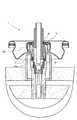
本発明の弁体(1)は、様々な理由のために、保存の間互いに分離される必要がある少なくとも2つの流体を封入した分配フラスコを閉じるためのものである。弁体(1)はキューペル(2)などの固定手段によって、図示されていない硬質フラスコに固定されている。外側継手(21)はその間に気密を保つためにフラスコ頸部とキューペル(2)の間に配置されている。従来の仕方で、弁体(1)はキューペル(2)のドーム(22)の上に固定される。 The valve body (1) of the present invention is for closing a dispensing flask containing at least two fluids that need to be separated from each other during storage for various reasons. The valve body (1) is fixed to a hard flask (not shown) by fixing means such as a cupel (2). An outer joint (21) is placed between the flask neck and cupel (2) to keep it airtight therebetween. In a conventional manner, the valve body (1) is fixed on the dome (22) of the cupel (2).
弁体(1)は主として下記によって構成される。
キューペル(2)のドーム(22)に固定された弁体(9)、閉鎖位置と開放位置の間で軸方向に移動することができる弁体(9)内に位置づけられたステム(4)、ステム(4)を閉鎖位置に戻そうとするバネ(8)、タイ(3)、および、2つの内部継手(5、6)。
The valve body (1) is mainly constituted by the following.
A valve body (9) fixed to the dome (22) of the cupell (2), a stem (4) positioned in the valve body (9) capable of moving axially between a closed position and an open position; A spring (8) trying to return the stem (4) to the closed position, a tie (3), and two internal joints (5, 6).
2つの軟質パウチ(11、12)は、弁体(9)に溶接され、第一のパウチ(11)は第二のパウチ(12)の内部に配置される。 The two soft pouches (11, 12) are welded to the valve body (9), and the first pouch (11) is disposed inside the second pouch (12).
弁体(9)は、キューペル(2)のドーム(22)内に固定されるための同心クラウン形を有する上部(91)で構成される。第一の内部継手(5)は、この上部(91)の正面とドーム(22)の底部の間に、気密性保持のために配置される。この気密性はこの上部(91)の前面の三角形の横断面によって向上する。 The valve body (9) is composed of an upper part (91) having a concentric crown shape for fixing in the dome (22) of the cupel (2). The first inner joint (5) is arranged between the front of the upper part (91) and the bottom of the dome (22) for airtightness. This tightness is improved by the triangular cross section of the front surface of this upper part (91).
弁体(9)のこの上部クラウン(91)は外径が小さい中間円筒環状部分によって延長され、後者は次いで同心で、この中間環状部分の部位で相互に接続された2つのほぼ円筒状の主部分(92,93)に分かれている。小穴(94)はこの中間結合区域内に開けられて、2つの主部分(92,93)の間に位置する環状導管と上部クラウン(91)の内部に位置づけられた空間を接触させる。 This upper crown (91) of the valve body (9) is extended by an intermediate cylindrical annular part with a small outer diameter, the latter then being concentric and two generally cylindrical main parts interconnected at the part of this intermediate annular part. It is divided into parts (92, 93). The eyelet (94) is drilled in this intermediate coupling area to contact the annular conduit located between the two main parts (92, 93) and the space located inside the upper crown (91).
第一の主部分(92)は軸方向導管(95)の中心に向けられた放射状リブをその下部に備えた軸状導管(95)が貫通している。これらのリブの放射状長さは連続的に3段階で増加する。リブ(96)の第一段は、一方では、その上部において、後述の継手の当止め、他方でステム(4)摺動のための案内の役割を果たし、リブ(97)の第二段はバネ(8)の案内を保証し、リブ(98)の第三段はその上部において、バネ(8)の支えの役割を果たす。リブの第三の組(98)を延長する下部ピボット(99)は第一のパウチ(11)内に沈み込ませる短管を配置するために備えられている。 The first main portion (92) is penetrated by an axial conduit (95) with radial ribs at the bottom directed toward the center of the axial conduit (95). The radial length of these ribs increases continuously in three steps. The first stage of the rib (96), on the one hand, serves as a stopper for the later-described joint, and on the other hand serves as a guide for sliding the stem (4), and the second stage of the rib (97) is Guarantees the guide of the spring (8), and the third stage of the rib (98) serves as a support for the spring (8) in its upper part. A lower pivot (99) extending the third set of ribs (98) is provided for placing a short tube to be submerged in the first pouch (11).
第二の主部分(93)は第一の主部分(92)の上部を囲繞する円筒状キューペルの形を有する。このキューペル(93)と第一の主部分(92)の外面との間に第一の主部分(92)と同心で下に向かって開いている環状導管が形成される。この環状導管の上端は小穴(94)で終わっている。 The second main part (93) has the shape of a cylindrical cupel surrounding the top of the first main part (92). An annular conduit is formed between the cupel (93) and the outer surface of the first main portion (92) that is concentric with the first main portion (92) and opens downward. The upper end of the annular conduit ends with a small hole (94).
第一の軟質パウチ(11)はキューペル(93)からはみ出ている第一の主部分(92)の外面に溶接され、第二の軟質パウチ(12)はカラー状の第二主部分(93)の外面に固定される。これらのパウチは例えば、溶接によって固定される。2つのパウチ(11、12)はどこも閉鎖され、それぞれ第一の流路(42、45、95)と第二の流路(47、48、94)を介してしか外部と連通できない。 The first soft pouch (11) is welded to the outer surface of the first main portion (92) protruding from the cupel (93), and the second soft pouch (12) is a collar-shaped second main portion (93). It is fixed to the outer surface. These pouches are fixed by welding, for example. The two pouches (11, 12) are all closed and can communicate with the outside only through the first flow path (42, 45, 95) and the second flow path (47, 48, 94), respectively.
ステム(4)はほぼ円筒状の外形を有し、下端(43)が閉じられた中央孔(42)を形成する第一の円筒状壁(41)を備えている。ステム(4)の下端は内径がステム(4)の外径よりも小さな円筒状ピボット(44)で終わっている。バネ(8)はこのピボット(44)の上に配置される。第一の放射状孔(45)は中央孔(42)の下端の近くで、ステム(4)の第一の壁(41)内に開けられる。したがって、この第一の放射状孔(45)は中央孔(42)の内部とステム(4)の外面を接触させる。 The stem (4) has a substantially cylindrical outer shape and is provided with a first cylindrical wall (41) forming a central hole (42) closed at the lower end (43). The lower end of the stem (4) ends with a cylindrical pivot (44) whose inner diameter is smaller than the outer diameter of the stem (4). The spring (8) is placed on this pivot (44). A first radial hole (45) is drilled in the first wall (41) of the stem (4) near the lower end of the central hole (42). Therefore, this first radial hole (45) brings the inside of the central hole (42) and the outer surface of the stem (4) into contact.
ステム(4)はさらに第一の壁(41)と同心な第二の円筒状壁(46)を備え、第二の壁は第一の壁(41)を囲繞して中心孔(42)と同心の環状導管(47)を形成する。この環状導管(47)は上部に向けて開き、下部に向けて閉じ、第一の放射状孔(45)がそれを貫通しないような長さを有する。第二の放射状孔(48)は第二の円筒状壁(46)を貫通して環状導管(47)の内部とステム(4)の外部を接触させる。 The stem (4) further comprises a second cylindrical wall (46) concentric with the first wall (41), the second wall surrounding the first wall (41) and the central hole (42). A concentric annular conduit (47) is formed. The annular conduit (47) opens toward the top and closes toward the bottom and has a length such that the first radial hole (45) does not penetrate it. The second radial hole (48) passes through the second cylindrical wall (46) to contact the interior of the annular conduit (47) with the exterior of the stem (4).
ステム(4)はさらにその外周上に位置づけられた2つ以上の円形当止め(49a、49b)を備え、第一のもの(49a)は第一の放射状孔(45)のわずかに下にあってステム(4)の中心孔(42)とその外部を接触させ、第二のもの(49b)は第二の放射状孔(48)のわずかに下にあって環状導管(47)の内部とステム(4)の外部を接触させる。第一の当止め(49a)の外径は弁体(9)の軸方向導管(95)のリブ(96)の第一部分の内側端によって形成された円筒の直径にほぼ対応している。第二当止め(49b)の外径はタイ(3)の内径にほぼ対応している。 The stem (4) further comprises two or more circular stoppers (49a, 49b) positioned on its outer circumference, the first one (49a) being slightly below the first radial hole (45). The center hole (42) of the stem (4) is brought into contact with the outside, and the second (49b) is slightly below the second radial hole (48) so that the inside of the annular conduit (47) and the stem The outside of (4) is brought into contact. The outer diameter of the first stop (49a) substantially corresponds to the diameter of the cylinder formed by the inner end of the first portion of the rib (96) of the axial conduit (95) of the valve body (9). The outer diameter of the second stopper (49b) substantially corresponds to the inner diameter of the tie (3).
タイ(3)は、その上部に外側に向かう放射状リブ(31)を備えた中空円筒で形成されている。 The tie (3) is formed of a hollow cylinder provided with radial ribs (31) directed outward at the top thereof.
組み立てた状態で、弁体(9)は例えば、はめ込み接合によってキューペル(2)に固定されている。バネ(8)はリブの第三段(98)に当たって、このリブの第二段(97)によって形成された導管内に導かれる弁体(9)の片側から他の側に貫通する軸方向導管(95)内に配置される。ステム(4)は弁体(9)内に配置され、そのピボット(44)は下に向けられ、バネ(8)の上端内に配置される。第二のOリング(6)はステム(4)の上に配置されてそれを締め付けて気密性を確保するが、その摺動性を阻止するわけではない。それはリブ(96)の第一段で当止めされる。最後に、タイ(3)は弁体(9)の軸方向導管(95)の内部に、第一の内部継手(5)と第二の内部継手(6)の間でステム(4)の周囲に配置される。 In the assembled state, the valve body (9) is fixed to the cupell (2) by, for example, fitting joint. The spring (8) hits the third stage (98) of the rib and passes through from one side of the valve body (9) which is led into the conduit formed by the second stage (97) of this rib to the other side. (95). The stem (4) is arranged in the valve body (9), its pivot (44) is directed downward and is arranged in the upper end of the spring (8). The second O-ring (6) is disposed on the stem (4) and tightens it to ensure hermeticity, but does not prevent its slidability. It is secured in the first stage of the rib (96). Finally, the tie (3) is placed around the stem (4) between the first inner joint (5) and the second inner joint (6) inside the axial conduit (95) of the valve body (9). Placed in.
ステム(4)の当止め(49a、49b)はステム(4)がバネ(8)によって上方に押し戻される閉鎖位置で、第二の当止め(49b)が第一の内部継手(5)の内面に押しつけられ、第一の当止め(49a)が第二の内部継手(6)の内面に押しつけられるように配置される。したがって、ステム(4)は弁体(1)から出ることができない。 The stopper (49a, 49b) of the stem (4) is in the closed position where the stem (4) is pushed back upward by the spring (8), and the second stopper (49b) is the inner surface of the first inner joint (5). The first stopper (49a) is arranged to be pressed against the inner surface of the second inner joint (6). Therefore, the stem (4) cannot exit from the valve body (1).
一方の中心孔(42)と他方の環状導管(47)をステム(4)の外部と接触させる放射状孔(45、48)は、閉鎖位置でこれらの放射状孔(45、48)がそれぞれ第一の内部継手(6)と第一の内部継手(5)の部位で開口し、それによって片目孔を形成するように配置されている。したがって、ステム(4)の第一の壁(41)と第二の壁(46)は可動性壁を形成し、可動性壁は放射状孔(45、48)をあるいはそれらを閉じることによって、すなわちそれぞれ第2と第一の内部継手(6,5)を閉じることによって壁の前に、あるいはそれぞれ第一と第二のパウチ(11、12)の内部と接触している空間に向かい合わせることができる。 The radial holes (45, 48) for bringing one central hole (42) and the other annular conduit (47) into contact with the outside of the stem (4) are respectively in the closed position. The inner joint (6) and the first inner joint (5) are opened so as to form a one-eye hole. Thus, the first wall (41) and the second wall (46) of the stem (4) form a movable wall, which can be achieved by closing the radial holes (45, 48) or closing them, ie By closing the second and first inner joints (6, 5) respectively, facing the space in front of the wall or in contact with the interior of the first and second pouches (11, 12), respectively. it can.
とりわけ第二の内部継手(6)によって、一方の、第一の主部分(92)の内部と接触している第一のパウチ(11)の内部と、他方のカラー(93)と第一の主部分(92)の間に位置する環状空間および弁体(9)の上部クラウン(91)の内部に位置する空間と接触している第二のパウチ(12)の内部の間に物理的分離が存在する。 In particular, by means of the second internal joint (6), the interior of the first pouch (11) in contact with the interior of one of the first main parts (92) and the other collar (93) and the first Physical separation between the annular space located between the main parts (92) and the interior of the second pouch (12) in contact with the space located inside the upper crown (91) of the valve body (9) Exists.
例えば、弁体の上に配置された拡散板によって、容器の外に出ているステム(4)の上端に下向きの軸方向力がかかったとき、ステム(4)はバネ(8)の力に抗して弁体(9)内に下向きに移動し、放射状孔(44、48)は内部継手(5,6)から出て、パウチ(11、12)内の流体のために2つの流路が開かれる。 For example, when a downward axial force is applied to the upper end of the stem (4) that is outside the container by the diffusion plate disposed on the valve body, the stem (4) is subjected to the force of the spring (8). In contrast, it moves downward into the valve body (9) and the radial holes (44, 48) exit the internal joints (5, 6) and have two flow paths for the fluid in the pouch (11, 12). Is opened.
第一のパウチ(11)内に含まれる流体はピボット(99)を通過し、次いでリブの異なる段(96,97,98)の間に位置する空間内を通過してから、第一の放射状孔(45)を横断し、ステム(4)の中央孔(42)を通って、弁体(1)の外に出る。 The fluid contained in the first pouch (11) passes through the pivot (99) and then through the space located between the different steps (96, 97, 98) of the ribs before the first radial. Cross the hole (45), pass through the central hole (42) of the stem (4) and out of the valve body (1).
第二のパウチ(12)内に含まれる流体はカラー形の第一の主部分(92)と第二の主部分(93)の間に位置する環状空間を通過し、小穴(94)を通って、タイ(3)のリブ(31)の間の上部クラウン(91)内に位置する空間に到達し、第二の放射状孔(48)、次いで軸方向導管(47)を通過してから外に出る。 The fluid contained in the second pouch (12) passes through the annular space located between the collar-shaped first main portion (92) and the second main portion (93) and passes through the small hole (94). To reach the space located in the upper crown (91) between the ribs (31) of the tie (3), pass through the second radial hole (48) and then the axial conduit (47) before Get out.
ステム(4)の上端で初めて両方の流体が出会う。 Both fluids meet for the first time at the upper end of the stem (4).
駆動手段は容器内部に入れられた気体によって通常の仕方で構成される。軟質パウチ(11,12)は気体と接触しないが、気体が外側パウチ(12)の壁に掛ける圧力を受ける。この第二のパウチの流体は圧力を内側パウチ(11)に伝達する。 The drive means is constructed in the usual way by a gas placed inside the container. The soft pouches (11, 12) do not come into contact with the gas, but are subjected to pressure that the gas applies to the wall of the outer pouch (12). The fluid in this second pouch transmits pressure to the inner pouch (11).
上述の例において、気体は容器から出ることができない。しかしながら、例えば、ステム(4)の遷移部分に、弁体が作動したときに第二の流体と同じ経路を通って気体が逃げることができるように閉鎖手段を備えた小穴を設けることもできるだろう。この駆動気体にそれと反応しない第三の流体を添加しても全く問題ない。このとき容器は保存の間物理的に分離される3つの流体を封入することになる。 In the above example, gas cannot exit the container. However, for example, a small hole with a closing means can be provided in the transition part of the stem (4) so that gas can escape through the same path as the second fluid when the valve body is actuated. Let's go. There is no problem even if a third fluid that does not react with the driving gas is added. The container then encloses three fluids that are physically separated during storage.
一方の中心孔(42)と他方の環状導管(47)をステム(4)の外部と接触させる放射状孔の数と寸法は必要に応じて、とりわけ2つの流体の間で採るべき体積比あるいはそれらそれぞれの粘度に応じて変えることができる。 The number and size of the radial holes that bring one central hole (42) and the other annular conduit (47) into contact with the outside of the stem (4) depends on the volume ratio to be taken between the two fluids or, if necessary, It can vary depending on the respective viscosity.
放射状孔(45、48)の配置は閉鎖位置において、第一と第二の内部継手(5、6)によって閉鎖され、開放位置で開かれるように選択される。しかしながら、それらを隔てる距離は内部継手(5、6)の下面を隔てる距離に正確に対応する必要はない。2つの距離が等しいとき、2つの孔は同時に開閉する。反対の場合、2つの内の一方が先に開き、他方は後で開くだろう。このようにして流路の一方を遅れて開くことができる。 The arrangement of the radial holes (45, 48) is selected to be closed in the closed position by the first and second inner joints (5, 6) and opened in the open position. However, the distance separating them need not correspond exactly to the distance separating the lower surfaces of the internal joints (5, 6). When the two distances are equal, the two holes open and close simultaneously. In the opposite case, one of the two will open first and the other will open later. In this way, one of the flow paths can be opened with a delay.
他方で、流路は同心である必要はない。それは平行であってもよく、重要なのはそれらが同一の弁体で開閉されることである。とりわけ、環状導管(47)は中心孔(42)に対して単に平行な導管に代えることができる。 On the other hand, the flow paths need not be concentric. It may be parallel, what is important is that they are opened and closed by the same valve body. In particular, the annular conduit (47) can be replaced by a conduit that is simply parallel to the central bore (42).
パウチは弁体の用途に応じて選択されるあらゆる種類の材料で実現することができる。 The pouch can be realized with any kind of material selected according to the application of the valve body.
実際には、弁体は第一段階で製造され、キューペル(2)に取り付けられる。パウチ(11、12)は巻かれ、接着バンドなどの保持手段によってその位置に維持される。このような形の弁体は充填工場に引き渡され、弁体による充填開始前に、弁体はそのキューペルによってフラスコに固定される。このとき接着バンドは充填圧力によって外れる。本発明による弁体は保管中に様々な成分を最終物質から分離しておくことが必要であるか、少なくとも必要に応じてその都度使用することができる。その用途分野はとくに医薬品、化粧品、農業食品にあるいは接着剤などの技術的使用に見いだされる。 In practice, the valve body is manufactured in the first stage and attached to the cupel (2). The pouches (11, 12) are wound and maintained in position by holding means such as an adhesive band. The valve body having such a shape is delivered to a filling factory, and the valve body is fixed to the flask by the cupel before the filling by the valve body is started. At this time, the adhesive band is released by the filling pressure. The valve body according to the present invention needs to separate various components from the final material during storage, or can be used at least as needed. Its field of application is found in particular in the technical use of pharmaceuticals, cosmetics, agricultural foods or adhesives.
1 二方弁体
11 第一パウチ
12 第二パウチ
2 キューペル
21 外側継手
22 ドーム
3 タイ
31 外側に向けられた放射状リブ
4 二方ステム
41 第一の円筒状壁
42 中心孔
43 中心孔下端
44 ピボット
45 第一の放射状孔
46 第二の円筒状壁
47 環状導管
48 第二の放射状孔
49a 第一当止め
49b 第二当止め
5 第一の内部継手
6 第二の内部継手
8 バネ
9 弁体
91 上部クラウン
92 第一主部分
93 カラー形の第二主部分
94 小穴
95 軸方向導管
96 リブの第一部分
97 リブの第二部分
98 リブの第三部分
99 下部ピボット
DESCRIPTION OF
Claims (10)
第一の流体を入れるための第一の軟質パウチ(11)、
第二の流体を入れるための第二の軟質パウチ(12)、
第一のパウチ(11)の内部と弁体(1)の外部を接続する第一の流路(42、45、95)、
第二のパウチ(12)の内部と弁体(1)の外部を接続する第二の流路(47、48、94)、
第一の流路(42、45、95)と第二の流路(47、48、94)を得るための閉塞手段(48、5)とから成り、
第一のパウチ(11)が第二のパウチ(12)の内部に配置される
ことを特徴とする弁体(1)。 In the valve body (1) fixed on a rigid container for the distribution of two fluids,
A first soft pouch (11) for containing a first fluid;
A second soft pouch (12) for containing a second fluid;
A first flow path (42, 45, 95) connecting the inside of the first pouch (11) and the outside of the valve body (1),
A second flow path (47, 48, 94) connecting the inside of the second pouch (12) and the outside of the valve body (1),
The first flow path (42, 45, 95) and the second flow path (47, 48, 94) and the closing means (48, 5) for obtaining,
The valve body (1), wherein the first pouch (11) is disposed inside the second pouch (12).
請求項1に記載の弁体(1)。 First closing means (45, 6) for causing the first flow path (42, 45, 95) to contact or isolate the inside of the first pouch (11) and the outside of the valve body (1) according to opening and closing. The second flow path (47, 48, 94) includes a second closing means (48) that contacts or isolates the inside of the second pouch (12) and the outside of the valve body (1) according to opening and closing. The valve body (1) according to claim 1, comprising 5).
請求項1または2に記載の弁体(1)。 The first channel and the second channel are in contact with the first soft pouch (11) when the respective closing means (45, 6/48, 5) are opened, and the other 3. The valve body (1) according to claim 1 or 2, wherein (47) consists of two concentric conduits (42, 47) capable of contacting a second soft pouch (12).
請求項1ないし3に記載の弁体(1)。 When the valve body is attached to the container, the space positioned inside the hard container can be brought into contact with or isolated from the outside of the valve body (1) according to opening and closing. A third flow path having a third blocking means, the third flow path being downstream of the first or second flow blocking means with respect to the fluid flow direction at the time of sampling. Or the valve body (1) of Claim 1 thru | or 3 which can be opened in a 2nd flow path.
請求項1ないし4に記載の弁体(1)。 Above the position where the closing means opens at least on one side of the second wall (5, 6) so as to form a one eye hole and on the space in contact with the inside of the pouch (11, 12) on one side, Holes (45, 48) opened in the movable walls (41, 46) between the positions opened on the spaces (41, 46) in contact with the outside of the valve element (1) on the other side. The valve body (1) according to any one of claims 1 to 4.
請求項1ないし5に記載の弁体(1)。 A valve body (9) which can be integrated with a cupel (2) fixed on a rigid container, and a stem (4) disposed in the valve body (9), and a closing means (45, 6/48) A stem (4) with means (8) capable of moving it between a first position in which 5) closes and a second position in which the closing means (45, 6/48, 5) open The valve body (1) according to claim 1 to 5.
請求項1ないし6に記載の弁体(1)。 The means for moving the stem (4) between the two positions consists of one spring (8) and another means on which the force can be exerted against the action of the spring (8). The valve body (1) according to claims 1 to 6.
下端(43)で閉じた中心孔(42)を形成し、中心孔(42)の底部近くに中心孔(42)の内部とステム(4)の外部を接触させる第一の放射状孔(45)を有する第一の円筒状壁(41)と、
第一の円筒状壁と同心で、2つの円筒状壁(41、46)の間に環状の導管(47)を形成するように第一の円筒状壁(41)の外側に位置する第二円筒状壁(46)であって、前記導管(47)が第一の放射状孔(45)と交差しないようにその上部で開口し、その下部で閉鎖され、環状導管(47)の内部とステム(4)の外部を接触させるように第二の放射状孔(48)が貫通している第二の壁(46)を備え、
弁体(9)が、
保持手段(98)によって軸方向導管(95)内に保持されたバネ(8)に対してステム(4)がその中で押しつけられる軸方向導管(95)を備えた第一の主部分(92)であって、その上に短管を配置することができる下部ピボット(99)を備えることが可能で、その外面の上に第一のパウチ(11)を固定することができる第一の主部分(92)と、
2つの主部分(92、93)の間に環状導管を形成するように部分的に第一の主部分(92)を覆うそれと同心のカラー形の第二の主部分(93)であって、この環状導管がその底部に、2つの主部分(92、93)の間の継ぎ目の部位に、小穴(94)を有する、第二の主部分(93)を備え、
第一流路の第一閉塞手段の一部を形成し、第二のパウチ(12)の内部と弁体の外部の間の気密性を確保する第一の継手(5)と、第二の流路の閉塞手段の一部を形成して、第一のパウチ(11)の内部と第二の流路の間の気密性を確保する第二の継手(6)を備える
請求項6または7に記載の弁体(1)。 Stem (4)
A central hole (42) closed at the lower end (43) is formed, and a first radial hole (45) for contacting the inside of the center hole (42) and the outside of the stem (4) near the bottom of the center hole (42). A first cylindrical wall (41) having:
A second concentric with the first cylindrical wall and located outside the first cylindrical wall (41) so as to form an annular conduit (47) between the two cylindrical walls (41, 46). A cylindrical wall (46), wherein the conduit (47) opens at the top thereof so as not to intersect the first radial hole (45) and is closed at the bottom thereof, and the inside of the annular conduit (47) and the stem A second wall (46) through which a second radial hole (48) passes so as to contact the outside of (4),
The disc (9)
A first main part (92) comprising an axial conduit (95) in which the stem (4) is pressed against a spring (8) held in the axial conduit (95) by a retaining means (98). A first main pouch (11) on which the first pouch (11) can be fixed on the outer surface of the lower pivot (99). Part (92);
A concentric collar-shaped second main portion (93) partially covering the first main portion (92) so as to form an annular conduit between the two main portions (92, 93); This annular conduit comprises at its bottom a second main part (93) having a small hole (94) at the seam between the two main parts (92, 93);
A first joint (5) that forms part of the first closing means of the first flow path and secures airtightness between the inside of the second pouch (12) and the outside of the valve body, and the second flow 8. A second coupling (6) comprising a second joint (6) which forms part of the passage blocking means and ensures the airtightness between the interior of the first pouch (11) and the second flow path. The valve body (1) described.
請求項1ないし8に記載の弁体(1)。 The valve body (1) according to any one of claims 1 to 8, comprising driving means mounted on a rigid container and constituted by means for applying pressure to the second soft pouch (12).
請求項1ないし9に記載の弁体(1)。 The means for applying pressure to the second soft pouch (12) comprises a pressurized gas enclosed in a rigid container having two pouches (11, 12) disposed therein. The valve body (1) described.
Applications Claiming Priority (2)
| Application Number | Priority Date | Filing Date | Title |
|---|---|---|---|
| FR0651759A FR2901255B1 (en) | 2006-05-16 | 2006-05-16 | VALVE HAS TWO WAYS |
| PCT/EP2007/054780 WO2007132017A1 (en) | 2006-05-16 | 2007-05-16 | Two-way valve |
Publications (1)
| Publication Number | Publication Date |
|---|---|
| JP2009537403A true JP2009537403A (en) | 2009-10-29 |
Family
ID=37497041
Family Applications (1)
| Application Number | Title | Priority Date | Filing Date |
|---|---|---|---|
| JP2009510458A Pending JP2009537403A (en) | 2006-05-16 | 2007-05-16 | Two-way valve body |
Country Status (18)
| Country | Link |
|---|---|
| US (2) | US8317062B2 (en) |
| EP (1) | EP2024256B1 (en) |
| JP (1) | JP2009537403A (en) |
| CN (1) | CN101443243B (en) |
| AU (1) | AU2007251560B2 (en) |
| BR (1) | BRPI0712793B1 (en) |
| CA (1) | CA2652321C (en) |
| DK (1) | DK2024256T3 (en) |
| ES (1) | ES2400921T3 (en) |
| FR (1) | FR2901255B1 (en) |
| HK (1) | HK1130751A1 (en) |
| MX (1) | MX2008014255A (en) |
| NO (1) | NO20085095L (en) |
| PL (1) | PL2024256T3 (en) |
| PT (1) | PT2024256E (en) |
| RU (1) | RU2404910C2 (en) |
| WO (1) | WO2007132017A1 (en) |
| ZA (1) | ZA200809636B (en) |
Cited By (2)
| Publication number | Priority date | Publication date | Assignee | Title |
|---|---|---|---|---|
| WO2012057342A1 (en) | 2010-10-29 | 2012-05-03 | 株式会社ダイゾー | Aerosol container for multiple fluid discharge, multiple fluid discharge aerosol product, and internal container used therefor |
| WO2021049461A1 (en) * | 2019-09-13 | 2021-03-18 | 株式会社三谷バルブ | Contents ejecting unit and ejecting container |
Families Citing this family (20)
| Publication number | Priority date | Publication date | Assignee | Title |
|---|---|---|---|---|
| FR2901255B1 (en) * | 2006-05-16 | 2010-12-10 | Lindal France | VALVE HAS TWO WAYS |
| DE102009055125A1 (en) | 2009-10-30 | 2011-05-05 | Henkel Ag & Co. Kgaa | Cosmetic product, useful as hair coloring-, hair caring- and/or a hair styling-preparation, comprises a formulation comprising two free-flowing components, and an associated pressure vessel for storing and dispensing the components |
| DE102009055280A1 (en) * | 2009-12-23 | 2011-06-30 | Henkel AG & Co. KGaA, 40589 | Hairstyling process using water-based hairstyling compositions |
| MY161797A (en) * | 2010-05-05 | 2017-05-15 | Joseph Company Int Inc | Over pressure release valve |
| FR2961795A1 (en) * | 2010-06-28 | 2011-12-30 | Lindal France Sas | DOSING VALVE FOR PRESSURIZED BOTTLE |
| JP2013537504A (en) | 2010-08-16 | 2013-10-03 | バイエル・マテリアルサイエンス・アクチェンゲゼルシャフト | Discharge module |
| CN103153480B (en) | 2010-08-16 | 2016-09-14 | 科思创德国股份有限公司 | Distribution module and the method being used for filling distribution module |
| FR2965799B1 (en) | 2010-10-06 | 2012-10-05 | Lindal France Sas | DIFFUSER FOR MULTIVOIE VALVE |
| EP2457847A3 (en) | 2012-02-16 | 2012-06-27 | Bayer MaterialScience AG | Dispensing module for industrial coating agents |
| EP2457848A3 (en) | 2012-02-16 | 2012-06-27 | Bayer MaterialScience AG | Dispensing module for medical coating agents |
| EP2457846A3 (en) | 2012-02-16 | 2012-06-27 | Bayer MaterialScience AG | Dispensing module for cosmetic compounds |
| US8800824B2 (en) | 2012-02-29 | 2014-08-12 | Alfonso M. Gañan-Calvo | Sequential delivery valve apparatus and methods |
| US10160591B1 (en) * | 2012-06-27 | 2018-12-25 | Precision Valve Corporation | Aerosol valves for soluble compressed gas propellants |
| US9586217B2 (en) * | 2012-10-04 | 2017-03-07 | Arminak & Associates, Llc | Mixing chamber for two fluid constituents |
| EP3197607B1 (en) * | 2014-09-23 | 2021-10-20 | Sika Technology AG | Head plate device, storage container device, cartridge arrangement, dispensing apparatus, and their usage |
| FR3071579B1 (en) * | 2017-09-27 | 2019-09-27 | Lindal France | VALVE STEM FOR TWO-WAY VALVE |
| CN109958809A (en) * | 2017-12-14 | 2019-07-02 | 富利乐科技(深圳)有限公司 | Two-way valve and can pultrusion modified product |
| US10369579B1 (en) | 2018-09-04 | 2019-08-06 | Zyxogen, Llc | Multi-orifice nozzle for droplet atomization |
| FR3099470B1 (en) | 2019-07-29 | 2021-09-10 | Lindal France | Pressure vessel valve |
| IT201900015830A1 (en) * | 2019-09-06 | 2021-03-06 | Coster Tecnologie Speciali Spa | Device for dispensing a fluid substance |
Citations (3)
| Publication number | Priority date | Publication date | Assignee | Title |
|---|---|---|---|---|
| JPS6439288U (en) * | 1987-01-08 | 1989-03-08 | ||
| JP2004244109A (en) * | 2003-01-24 | 2004-09-02 | Toyo Aerosol Ind Co Ltd | Aerosol device for two-liquid delivery |
| JP2005206158A (en) * | 2004-01-20 | 2005-08-04 | Mitani Valve Co Ltd | Multi-liquid mixing and discharging type aerosol container |
Family Cites Families (17)
| Publication number | Priority date | Publication date | Assignee | Title |
|---|---|---|---|---|
| US3474934A (en) * | 1967-11-30 | 1969-10-28 | Sterling Drug Inc | Apparatus for dispensing a plurality of materials simultaneously |
| US3455489A (en) * | 1968-02-08 | 1969-07-15 | Philip Meshberg | Dispensing two materials simultaneously from different compartments |
| FR2057241A6 (en) * | 1969-08-07 | 1971-05-21 | Oreal | |
| DE1786036A1 (en) * | 1968-08-09 | 1971-07-15 | Bi Aerosol Verpackungs Gmbh & | Device for the separate intake and joint delivery of liquid to pasty materials |
| US3682355A (en) * | 1970-01-06 | 1972-08-08 | Johnson & Son Inc S C | Pressure actuated valve |
| US3685695A (en) * | 1970-08-28 | 1972-08-22 | Fluid Chem Co Inc | Marblelized product aerosol dispenser |
| DE2160268C3 (en) * | 1971-12-04 | 1974-07-25 | Andreae & Mayer Gmbh, 5000 Koeln | Pressurized gas can for a spray device |
| EP0098476A3 (en) * | 1982-07-06 | 1985-07-31 | Aerosol-Service Ag | Container for a pressurised product |
| US6736288B1 (en) * | 2000-10-26 | 2004-05-18 | Ronald D. Green | Multi-valve delivery system |
| DE60124534T2 (en) * | 2000-05-19 | 2007-09-20 | The Gillette Co., Boston | DEVICE FOR DISTRIBUTING MULTICOMPONENT MATERIALS |
| DE10046149A1 (en) * | 2000-09-15 | 2002-03-28 | Hilti Ag | Pressurized container has crimped surfaces at surface contact points and gas sealing material applied between surfaces before crimping |
| DE20113023U1 (en) * | 2001-08-04 | 2002-12-19 | Lindal Gmbh Aerosol Tech | Valve for the removal of flowable media from a pressure-tight container using a fluid propellant in the container |
| BRPI0311148B1 (en) * | 2002-05-21 | 2015-09-22 | Aptargroup Inc | improved aerosol dispenser, and process for filling the same |
| US7357158B2 (en) * | 2002-05-21 | 2008-04-15 | Seaquist Perfect Dispensing Foreign | Aerosol dispenser for mixing and dispensing multiple fluid products |
| US20040084477A1 (en) * | 2002-11-04 | 2004-05-06 | Gary Albaum | Container |
| WO2005087616A1 (en) | 2004-03-16 | 2005-09-22 | Loctite (R & D) Limited | Dispenser for co-dispensing two or more materials |
| FR2901255B1 (en) * | 2006-05-16 | 2010-12-10 | Lindal France | VALVE HAS TWO WAYS |
-
2006
- 2006-05-16 FR FR0651759A patent/FR2901255B1/en not_active Expired - Fee Related
-
2007
- 2007-05-16 CN CN200780017605XA patent/CN101443243B/en not_active Expired - Fee Related
- 2007-05-16 MX MX2008014255A patent/MX2008014255A/en active IP Right Grant
- 2007-05-16 EP EP07729228A patent/EP2024256B1/en active Active
- 2007-05-16 CA CA2652321A patent/CA2652321C/en active Active
- 2007-05-16 PT PT77292282T patent/PT2024256E/en unknown
- 2007-05-16 DK DK07729228.2T patent/DK2024256T3/en active
- 2007-05-16 PL PL07729228T patent/PL2024256T3/en unknown
- 2007-05-16 AU AU2007251560A patent/AU2007251560B2/en not_active Ceased
- 2007-05-16 WO PCT/EP2007/054780 patent/WO2007132017A1/en active Application Filing
- 2007-05-16 RU RU2008149506/12A patent/RU2404910C2/en not_active IP Right Cessation
- 2007-05-16 BR BRPI0712793-6A patent/BRPI0712793B1/en active IP Right Grant
- 2007-05-16 ES ES07729228T patent/ES2400921T3/en active Active
- 2007-05-16 JP JP2009510458A patent/JP2009537403A/en active Pending
- 2007-05-16 US US12/300,498 patent/US8317062B2/en active Active
-
2008
- 2008-11-12 ZA ZA200809636A patent/ZA200809636B/en unknown
- 2008-12-08 NO NO20085095A patent/NO20085095L/en not_active Application Discontinuation
-
2009
- 2009-09-25 HK HK09108787.1A patent/HK1130751A1/en not_active IP Right Cessation
-
2012
- 2012-10-19 US US13/656,191 patent/US8505775B2/en active Active
Patent Citations (3)
| Publication number | Priority date | Publication date | Assignee | Title |
|---|---|---|---|---|
| JPS6439288U (en) * | 1987-01-08 | 1989-03-08 | ||
| JP2004244109A (en) * | 2003-01-24 | 2004-09-02 | Toyo Aerosol Ind Co Ltd | Aerosol device for two-liquid delivery |
| JP2005206158A (en) * | 2004-01-20 | 2005-08-04 | Mitani Valve Co Ltd | Multi-liquid mixing and discharging type aerosol container |
Cited By (7)
| Publication number | Priority date | Publication date | Assignee | Title |
|---|---|---|---|---|
| WO2012057342A1 (en) | 2010-10-29 | 2012-05-03 | 株式会社ダイゾー | Aerosol container for multiple fluid discharge, multiple fluid discharge aerosol product, and internal container used therefor |
| CN103189283A (en) * | 2010-10-29 | 2013-07-03 | 株式会社大造 | Aerosol container for multiple fluid discharge, multiple fluid discharge aerosol product, and internal container used therefor |
| JPWO2012057342A1 (en) * | 2010-10-29 | 2014-05-12 | 株式会社ダイゾー | Multi-liquid discharge aerosol container, multi-liquid discharge aerosol product and internal container used therefor |
| CN103189283B (en) * | 2010-10-29 | 2015-01-07 | 株式会社大造 | Aerosol container for multiple fluid discharge, multiple fluid discharge aerosol product, and internal container used therefor |
| JP5952739B2 (en) * | 2010-10-29 | 2016-07-13 | 株式会社ダイゾー | Multi-liquid discharge aerosol container, multi-liquid discharge aerosol product and internal container used therefor |
| WO2021049461A1 (en) * | 2019-09-13 | 2021-03-18 | 株式会社三谷バルブ | Contents ejecting unit and ejecting container |
| CN114007955A (en) * | 2019-09-13 | 2022-02-01 | 三谷阀门有限公司 | Content discharge unit and discharge container |
Also Published As
| Publication number | Publication date |
|---|---|
| US20130037571A1 (en) | 2013-02-14 |
| RU2008149506A (en) | 2010-06-27 |
| AU2007251560B2 (en) | 2011-02-10 |
| WO2007132017A1 (en) | 2007-11-22 |
| EP2024256A1 (en) | 2009-02-18 |
| NO20085095L (en) | 2008-12-08 |
| CN101443243A (en) | 2009-05-27 |
| US8317062B2 (en) | 2012-11-27 |
| PT2024256E (en) | 2013-03-04 |
| ZA200809636B (en) | 2009-11-25 |
| FR2901255A1 (en) | 2007-11-23 |
| HK1130751A1 (en) | 2010-01-08 |
| BRPI0712793A2 (en) | 2012-09-04 |
| US20090230344A1 (en) | 2009-09-17 |
| MX2008014255A (en) | 2009-02-12 |
| CN101443243B (en) | 2010-12-08 |
| PL2024256T3 (en) | 2013-06-28 |
| CA2652321A1 (en) | 2007-11-22 |
| AU2007251560A1 (en) | 2007-11-22 |
| CA2652321C (en) | 2012-07-17 |
| BRPI0712793A8 (en) | 2017-11-21 |
| BRPI0712793B1 (en) | 2019-04-02 |
| FR2901255B1 (en) | 2010-12-10 |
| RU2404910C2 (en) | 2010-11-27 |
| DK2024256T3 (en) | 2013-03-18 |
| ES2400921T3 (en) | 2013-04-15 |
| EP2024256B1 (en) | 2012-12-19 |
| US8505775B2 (en) | 2013-08-13 |
Similar Documents
| Publication | Publication Date | Title |
|---|---|---|
| JP2009537403A (en) | Two-way valve body | |
| US9624021B2 (en) | Dispensing module | |
| EP1702862A2 (en) | Self-sealing nozzle for a dispensing apparatus | |
| ES2876003T3 (en) | High flow aerosol valve | |
| US10071849B2 (en) | Valve assembly | |
| JP5336192B2 (en) | Valve for flowable material and its closure means | |
| KR101697034B1 (en) | Spray head and container provided with same | |
| SK8492001A3 (en) | Container for dispensing fluid, comprising a pressure control device with activation step | |
| KR101430988B1 (en) | Cosmetic vessel having mixed two-type materials | |
| JP2013537503A (en) | Delivery module and method for filling delivery module | |
| JP2016510290A (en) | Metering valve | |
| JP2018100128A (en) | Non-refillable aerosol valve | |
| JP2013530897A (en) | Metering valve for pressurized vials | |
| JP5687623B2 (en) | Fluid dispenser device | |
| JP2003118785A (en) | Valve for device for receiving and feeding pressurized liquid, and device including the same | |
| JP5656714B2 (en) | Contents extrusion container | |
| WO2006065585A3 (en) | Dispensing multi-component products | |
| EP0950434A1 (en) | Dispensing container provided with foaming device | |
| TW202327954A (en) | Multi-function aerosol valve assembly | |
| JPS62208380A (en) | Valve assembly and adapter used for valve assembly | |
| KR101040968B1 (en) | Spraying can enabling to discharge predetermined amount of gas with pouch and valve assembly thereof | |
| KR20180012628A (en) | Injection valve device for aerosol spray | |
| JPH0490864A (en) | Spray nozzle | |
| JP2000007064A (en) | Spray can | |
| JP2012206772A (en) | Content extrusion container |
Legal Events
| Date | Code | Title | Description |
|---|---|---|---|
| A621 | Written request for application examination |
Free format text: JAPANESE INTERMEDIATE CODE: A621 Effective date: 20100212 |
|
| A131 | Notification of reasons for refusal |
Free format text: JAPANESE INTERMEDIATE CODE: A131 Effective date: 20120131 |
|
| A521 | Request for written amendment filed |
Free format text: JAPANESE INTERMEDIATE CODE: A523 Effective date: 20120501 |
|
| A02 | Decision of refusal |
Free format text: JAPANESE INTERMEDIATE CODE: A02 Effective date: 20120605 |