JP2009533659A - Fixed amount collection device - Google Patents
Fixed amount collection device Download PDFInfo
- Publication number
- JP2009533659A JP2009533659A JP2009504647A JP2009504647A JP2009533659A JP 2009533659 A JP2009533659 A JP 2009533659A JP 2009504647 A JP2009504647 A JP 2009504647A JP 2009504647 A JP2009504647 A JP 2009504647A JP 2009533659 A JP2009533659 A JP 2009533659A
- Authority
- JP
- Japan
- Prior art keywords
- valve body
- opening
- discharge plunger
- plunger
- product
- Prior art date
- Legal status (The legal status is an assumption and is not a legal conclusion. Google has not performed a legal analysis and makes no representation as to the accuracy of the status listed.)
- Pending
Links
Images


Classifications
-
- G—PHYSICS
- G01—MEASURING; TESTING
- G01N—INVESTIGATING OR ANALYSING MATERIALS BY DETERMINING THEIR CHEMICAL OR PHYSICAL PROPERTIES
- G01N1/00—Sampling; Preparing specimens for investigation
- G01N1/02—Devices for withdrawing samples
- G01N1/10—Devices for withdrawing samples in the liquid or fluent state
- G01N1/20—Devices for withdrawing samples in the liquid or fluent state for flowing or falling materials
- G01N1/2035—Devices for withdrawing samples in the liquid or fluent state for flowing or falling materials by deviating part of a fluid stream, e.g. by drawing-off or tapping
-
- G—PHYSICS
- G01—MEASURING; TESTING
- G01F—MEASURING VOLUME, VOLUME FLOW, MASS FLOW OR LIQUID LEVEL; METERING BY VOLUME
- G01F11/00—Apparatus requiring external operation adapted at each repeated and identical operation to measure and separate a predetermined volume of fluid or fluent solid material from a supply or container, without regard to weight, and to deliver it
- G01F11/02—Apparatus requiring external operation adapted at each repeated and identical operation to measure and separate a predetermined volume of fluid or fluent solid material from a supply or container, without regard to weight, and to deliver it with measuring chambers which expand or contract during measurement
- G01F11/021—Apparatus requiring external operation adapted at each repeated and identical operation to measure and separate a predetermined volume of fluid or fluent solid material from a supply or container, without regard to weight, and to deliver it with measuring chambers which expand or contract during measurement of the piston type
-
- G—PHYSICS
- G01—MEASURING; TESTING
- G01N—INVESTIGATING OR ANALYSING MATERIALS BY DETERMINING THEIR CHEMICAL OR PHYSICAL PROPERTIES
- G01N1/00—Sampling; Preparing specimens for investigation
- G01N1/02—Devices for withdrawing samples
- G01N1/10—Devices for withdrawing samples in the liquid or fluent state
- G01N1/20—Devices for withdrawing samples in the liquid or fluent state for flowing or falling materials
- G01N1/2035—Devices for withdrawing samples in the liquid or fluent state for flowing or falling materials by deviating part of a fluid stream, e.g. by drawing-off or tapping
- G01N2001/205—Devices for withdrawing samples in the liquid or fluent state for flowing or falling materials by deviating part of a fluid stream, e.g. by drawing-off or tapping using a valve
- G01N2001/2057—Sample chamber in a valve/piston
Abstract
中を製品が送られる空洞(2,2a)、特に管路から、一定量の製品を回収する装置(1)および方法を開示する。この装置は、空洞(2a)内の出口開口(4)をシールするバルブボディ(5)と、定量回収室(9)とを備えている。本発明によると、このような装置は、流れの方向における出口開口(4)に隣接して配置されておりかつ専用の回収開口(10)を有する定量回収室(9)、を使用し、バルブボディ(5)に同軸に動かすことができる排出ピストン(14)を定量回収室(9)に送り込むことによって、無菌環境で製品が回収されるように、設計することができる。Disclosed is an apparatus (1) and method for recovering a certain amount of product from a cavity (2, 2a) through which the product is sent, particularly from a conduit. This device comprises a valve body (5) for sealing the outlet opening (4) in the cavity (2a), and a quantitative recovery chamber (9). According to the invention, such a device uses a metering recovery chamber (9), which is arranged adjacent to the outlet opening (4) in the direction of flow and has a dedicated recovery opening (10), and a valve. The product can be designed to be collected in a sterile environment by feeding a discharge piston (14) that can be moved coaxially to the body (5) into the metering collection chamber (9).
Description
本発明は、請求項1および請求項17の特徴記載部分に記載されているタイプの、製品供給中空空間から一定量の製品量を回収する装置および方法に関する。
The invention relates to an apparatus and a method for recovering a certain amount of product from a product supply hollow space of the type described in the characterizing parts of
このタイプの装置および方法は、特許文献1から公知である。この公知の装置は、製品の容積に関して定義される製品量を、製品供給管路から回収する役割を果たす。この装置は、製品供給管路に出口開口を備えており、この開口はバルブによってシールすることができる。この装置は、さらに、容積ランス(volume lance)の形式における定量回収室(dosing chamber)を含んでおり、この定量回収室の内側には排出プランジャが配置されている。容積ランスは、製品供給中空空間内の、出口開口とは反対側の位置から、製品供給中空空間の中を、出口開口まで移動することができる。容積ランスは、中空空間の中を動くにつれて、所定の製品量で満たされる。容積ランスが出口開口に入ると、容積ランスによって出口開口がシールされ、従って、出口バルブが開いた後、所定の製品量が排出プランジャによって容積ランスから回収容器の中に押し出される。その後、容積ランスは再び後退し、容積ランスによって出口開口がシールされている限りは、出口バルブは閉じたままである。次に、容積ランスおよび排出プランジャが初期ポジションに戻る。この公知の設計における欠点は、容積ランスを無菌で動作することができないことと、回収装置の殺菌が極めて限られていることである。
本発明の目的は、製品供給中空空間から一定量の製品量を回収し、殺菌が可能であり容易に行われる、装置および方法に関する。 An object of the present invention relates to an apparatus and a method for recovering a certain amount of product from a product supply hollow space and capable of being sterilized and easily performed.
この目的は、請求項1または請求項17に記載されている特徴によって解決される。 This object is solved by the features described in claim 1 or claim 17.
本発明による配置構成によると、定量回収室が出口開口の下流にあり、出口開口がバルブボディによってシールされ、定量回収室が自身の回収開口を有し、定量回収室が製品供給中空空間から隔てられている。この配置構成の結果として、定量回収した製品量を排出した後、定量回収室を容易に殺菌することができる。バルブボディと排出プランジャとが同軸に配置されている結果として、構造がコンパクトであり、容易に殺菌することができる。 According to the arrangement according to the invention, the metering chamber is downstream of the outlet opening, the outlet port is sealed by the valve body, the metering chamber has its own collecting aperture, and the metering chamber is separated from the product supply hollow space. It has been. As a result of this arrangement, the quantitative recovery chamber can be easily sterilized after discharging the quantitatively recovered product amount. As a result of the coaxial arrangement of the valve body and the discharge plunger, the structure is compact and can be easily sterilized.
本発明のさらなる有利な発展形態は、従属請求項から導くことができる。 Further advantageous developments of the invention can be derived from the dependent claims.
以下では、本発明の実施形態について図面を使用してさらに詳しく説明する。 Hereinafter, embodiments of the present invention will be described in more detail with reference to the drawings.
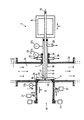
図1は、製品の容積に関して定義される一定量の製品量を、中空空間2(図示した実施形態においては製品供給管路である)から回収する、本発明による装置1を示している。中空空間2の中には、流動性の製品、例えば、液体、固体を有する液体、特に、食品(例えば果実加工物など)が存在している、または流れている。装置1は、微生物による汚染を調べる目的でサンプルを回収するのに特に適しているが、それ以外の目的にも使用することができる。 FIG. 1 shows an apparatus 1 according to the invention for recovering a certain amount of product, defined in terms of product volume, from a hollow space 2 (which in the illustrated embodiment is a product supply line). In the hollow space 2, a flowable product, for example, a liquid, a liquid having a solid, in particular, a food (for example, a processed fruit product) exists or flows. The device 1 is particularly suitable for collecting samples for the purpose of investigating contamination by microorganisms, but can also be used for other purposes.
装置1は、製品供給中空空間2aを含んでおり、この空間は、より大きな製品供給中空空間2の一部として形成されていることが有利である。図示した実施形態においては、中空空間2aはパイプソケット(pipe socket)3aによって囲まれており、パイプソケット3aは、中空空間2を含んでいる管路3にフランジを介して結合することができ、製品はこの管路3の中を流れ方向Fに流れる。出口開口4は、バルブシート4aによって囲まれており、パイプソケット3aの壁を、流れ方向Fに直角に貫通している。バルブシート4aは、バルブボディ5によってシールすることができる。図示した実施形態においては、バルブシート4aは中空空間2aの方向を向いており、バルブボディ5は中空空間2a内に位置しておりこの空間2a内で動く。これを目的として、バルブボディ5はバルブスピンドル6に連結されており、バルブスピンドル6は、出口開口4とは反対側のパイプソケット3aの壁における、シールされている開口7の中を通っており、駆動装置8の作用により、流れ方向Fを横切って両方向矢印Aの方向に動くことができる。
The device 1 includes a product supply
中空空間2aの外側には、定量回収室9が出口開口4に取り付けられている。定量回収室9は、回収する製品量の容積またはその整関数に対応する所定の容積を有する。定量回収室9は、好ましくは、円筒形状に形成されており、出口開口4の直径に本質的に一致する内径を有する。回収開口10は、出口開口4から遠い側の、定量回収室9の側面に位置している。回収開口10は、定量回収室9の直径および出口開口4の直径に一致する直径を有することが好ましい。出口開口4と、定量回収室9と、回収開口10は、それぞれの内面が合っている。回収開口10は、バルブ(例えばスライドバルブ)などの個別のシール装置によって、または、以下に詳しく説明するように回収容器12のシール11によって、シールすることができる。
A
回収開口10には、回収容器12のための連結装置13が割り当てられおり、この連結装置13によって、回収容器12を、結合が流体密封状態であるように回収開口10に取り付けることができる。連結装置13は、取り付けられる回収容器12(空気圧クランプ(pneumatic clamp)を含んでいることが好ましい)に適合するものである。
The
定量回収室9の中には、排出プランジャ14が配置されている。この排出プランジャ14は、定量回収室9の断面を覆っており、定量回収室9の内側において出口開口4から回収開口10まで、両方向矢印Bの方向に摺動させることができる。排出プランジャ14は、好ましくは出口開口4の内径と同じ外径を有する。
A
排出プランジャ14は、バルブボディ5と共にダブルシートバルブを形成している。排出プランジャ14は、バルブボディ5のバルブスピンドル6の中を通っているプランジャロッド15を介して作動し、このバルブスピンドル6は、中空であるように形成されており、駆動装置8(空気式の両方向駆動装置(pneumatic two-sided drive)として形成されている)に連結されている。
The discharge plunger 14 forms a double seat valve together with the valve body 5. The
プランジャロッド15も中空である。プランジャロッド15は、排出プランジャ14から遠い側における入口開口16と、定量回収室9の反対側における、排出プランジャ14付近の少なくとも1つの出口開口17とを含んでいる。プランジャロッド15の外径は、中空のバルブスピンドル6の内径よりも相当に小さく、従って、プランジャロッド15とバルブスピンドル6との間に流れ域18が存在しており、この流れ域18は、バルブボディ5における入口開口19と、中空空間2aの外側、バルブボディ5から遠い側における出口開口20とを含んでいる。出口開口20は、バルブスピンドル6の運動を妨げないように形成されている、または配置されており、例えば、出口開口20を、同軸方向に動くことができるようにバルブスピンドル6に取り付けることができる。
The
排出プランジャ14が、定量回収室9から完全に引っ込んだポジションに位置すると、入口開口19が排出プランジャ14によってシールされる。図示した実施形態においては、バルブシート5aは、出口開口4のバルブシート4aよりも半径方向内側にバルブボディ5上に延在しており、従って、排出プランジャ14は、引っ込んだポジションにあるとき、バルブシート5aに密着することができる。
When the
定量回収室9は、出口開口4に加えて追加の入口21を有し、回収開口10に加えてさらなる出口22を有する。入口21および出口22は、排出プランジャ14の運動方向Bに直角に延びており、シールすることができる。入口21および出口22は、バルブとして形成されていることが好ましい。
The
バルブスピンドル6のための貫通開口7には、バルブスピンドル6の外側のための殺菌装置23が割り当てられている。殺菌装置23は、中空空間2aからシールされている殺菌室24と、入口25および出口26(いずれも殺菌室24に接続されている)を含んでいる。
A
さらには、必要な殺菌ステップ中に殺菌温度に達するようにする一方で、回収動作時に、誤って製品が殺菌温度まで加熱される(それにより、製品の殺菌程度を判定する目的のサンプリング時に殺菌レベルが変化する)ことがないようにする目的で、熱センサー27a,27b,27cが装置1の中の適切な位置に配置されている。この場合、第1の熱センサー27aは定量回収室9の温度を監視し、第2の熱センサー27bは殺菌装置23の温度を監視し、第3の熱センサー27cは流れ域18における温度を監視する。さらなる熱センサー、もしくは別の位置における熱センサー、またはその両方を設けることができる。
Furthermore, during the required sterilization step, the product is accidentally heated to the sterilization temperature during the recovery operation (so that the sterilization level during sampling for the purpose of determining the degree of product sterilization). The
回収する必要がない動作の開始時、装置1は、図1に示したアイドルポジションにある。このアイドルポジションにおいては、バルブボディ5が出口開口4をシールしており、排出プランジャ14がバルブスピンドル6の開口19をシールしている。回収開口10は、開いている、または、適切な装置(図示していない)によってシールされている、または、以降の回収用にすでに連結されている回収容器12のシール11によってシールされている。製品は、中空空間2および2aの中を流れ方向Fに流れる。回収容器12は、あらかじめ殺菌しておき、所定の容量の栄養液を満たすことができる。
At the start of an operation that does not need to be recovered, the device 1 is in the idle position shown in FIG. In this idle position, the valve body 5 seals the outlet opening 4, and the discharge plunger 14 seals the
所定の製品量を回収する必要がある場合、最初に、回収容器12が連結した状態で、定量回収室9と、回収容器12のシール11と、定量回収室9に面している、排出プランジャ14の側面とを殺菌する。これを目的として、定量回収室9の中に入口20から殺菌物質(sterilization agent)を入れ、その後、出口21から再び取り除く。殺菌は、蒸気/凝縮水(steam/condensate)によって達成することが好ましい。
When it is necessary to collect a predetermined amount of product, first, with the
回収開口10がシールによってシールされており、入口開口がすでに殺菌されている回収容器を使用している場合、定量回収室9と、製品に接触するさらなる部分の初期殺菌は、製品供給の開始時に中空空間2または2aを殺菌することによって達成することもできる。
If the
回収容器12としては、欧州特許第263101号明細書から公知であるバッグまたはパウチを使用することが好ましい。このタイプの容器12のシール11は、連結装置13に取り付けることのできる充填要素(filling piece)11a(図3)を含んでいる。シール11はシールプラグ11bをさらに含んでおり、このシールプラグ11bは、充填要素11aを内側に対して、すなわち容器12の内部に対してシールし、容器12を開くためには、シールプラグ11bを充填要素11aから容器内側に押し出されなければならない。従って、このタイプの容器12は、事前に殺菌することのできるシールを備えておらず、充填前に、特に、シール11の前面11cの領域を殺菌しなければならない。本発明による装置1の場合、この殺菌は、プラグ11bが依然として充填要素11aの中に位置しており、前面11cが定量回収室9の境界を形成しているときに、説明した方法によってシール11を定量回収室9と一緒に殺菌することによって達成されることが好ましい。
As the
殺菌は、適切な温度、好ましくは約120度において行う。 Sterilization is performed at a suitable temperature, preferably about 120 degrees.
定量回収室9における温度が、もはや殺菌が行われない温度よりも(すなわちほぼ40度よりも)下がったことが熱センサー27aによって判定された場合、定量回収プロセスを開始することができる。この冷却は、製品が流れるにつれて製品自体によって達成され、なぜなら、定量回収室9が中空空間2または2aに直接接しているためである。
If the
定量回収プロセスにおいては、バルブボディ5と排出プランジャ14とから構成されているダブルシートバルブを出口開口4から持ち上げ(図2を参照)、従って、製品が中空空間2aから定量回収室9の中に流れ込むことができる。しかしながら、このとき、バルブスピンドル6の開口19は排出プランジャ14によって閉じられたままである。
In the quantitative recovery process, the double seat valve composed of the valve body 5 and the
定量回収室9が満たされた時点で、バルブボディ5と、開口19をシールしている排出プランジャ14とを備えたダブルシートバルブが、1つのユニットとして再びバルブシート4aまで動き、結果として、出口開口4を閉じる。このとき、バルブスピンドル6の外側は、殺菌物質(好ましくは蒸気/凝縮水)が中を流れている殺菌室23の中を動き、従って、バルブスピンドル6の殺菌されていない領域が中空空間2aの中に入ることはない。
When the fixed
出口開口4がシールされた時点で、回収容器12への流れを解放し、定量回収室9の中に存在している製品量を排出プランジャ14の支援下で回収容器12に押し出す。図示したバッグまたはパウチのシールを使用している場合、図示していない装置によって、または排出プランジャ14の圧力によって、プラグ11bを充填要素11aから押し出し、これにより、回収容器12を満たすことができる。定量回収室9から排出プランジャ14によって製品が排出されている間、バルブボディ5は、出口開口4をシールしているポジションのままである。その一方で、流れ経路18への開口19が解放される。プランジャロッド15の内側を通じて、すなわち、入口開口16および出口開口17を介して、無菌物質(例えば、無菌空気または無菌凝縮水)、あるいは場合によっては殺菌物質(例えば蒸気)が引き込まれる、または導入し、これらが排出プランジャ14および出口開口4より後ろの開口隙間を満たし、これにより、その後に製品もしくは例えば非無菌空気、またはその両方が吸い込まれることが防止される。
When the outlet opening 4 is sealed, the flow to the
製品が完全に排出され、排出プランジャ14は、図3に示した排出ポジションまで動く。このポジションにおいて、回収容器12をシールする、すなわち、図示した実施形態においては、プラグ11bを充填要素11aに押し込む。製品の第2の定量回収分を回収容器12に満たすことになっている場合、回収容器12を連結装置13に連結したままにする。そうでない場合、満たされた回収容器12を取り外して、新しい回収容器12に交換する、または、回収開口10を別の方法でシールする、または開いたままとする。
The product is completely discharged and the
次いで、排出プランジャ14を、バルブシート5aに接触している元の初期ポジションの方に駆動する。このとき、排出プランジャ14の後ろに存在している無菌物質が、流れ経路18への開口19を通じて、および出口20を通じて押し出される。プランジャロッド15の外側を殺菌する必要がある場合、この殺菌は、殺菌物質を流れ経路18に導入することによって行うことができる。排出プランジャ14が再びバルブシート5aに位置した時点で、定量回収室9への新しい充填プロセスを開始することができ、あるいは、回収開口10が閉じている場合、出口22が閉じたままで、蒸気または凝縮水、もしくは好ましくは無菌空気を入口21を介して定量回収室9に導入して定量回収室9を満たすことができる。新しい定量回収プロセスを開始する前に、出口22を開くことにより、定量回収室9の中に存在している物質(agent)を排出する。
Next, the
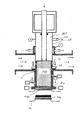
図4〜図6は、容積によって決定されている一定量の製品量を回収する、本発明による装置100の第2の実施形態を示している。装置100は、その設計が装置1に類似しており、異なる部分について以下に詳しく説明する。従って、同一・相当の構成要素は、図1〜図3と同じ参照数字によって表してあり、それらについては説明を繰り返さない。
4 to 6 show a second embodiment of the
装置100は、バルブボディ50を含んでおり、このバルブボディ50には、開口19より大きい中央開口190が設けられている。バルブボディ50は、中空空間2aの壁3aを貫いて定量回収室9に至る出口開口4を、バルブシールシート4aに着座するバルブ面50aを使用して、すでに説明した方式にてシールする。
The
開口190は、排出プランジャ140によって閉じられ、この排出プランジャ140は、前の実施形態の排出プランジャ14とは、より大きな寸法を有することにおいて異なる。排出プランジャ140は、好ましくは、円柱として形成されており、少なくとも出口開口4と回収開口10との間において定量回収室9を本質的に完全に満たす大きさを少なくとも有する。しかしながら、排出プランジャ140は、両方向矢印Bの方向に定量回収室9よりわずかに大きくすることができ、この場合、排出プランジャ140を回収開口10をわずかに超えて充填要素11aまで、あるいはサンプリング容器12の中まで動かすことができるように、回収開口10が形成されていることが好ましい。排出プランジャ140は、両方向矢印Bの方向に直角には、定量回収室9よりもわずかに小さい幅を有することが好ましく、従って、バルブシート面4aの境界縁部に対してシールをすべらせる必要がない。開口190におけるシールは、少なくとも、バルブボディ50に設けられているシールリング51によって行われる。シールリング51は、排出プランジャ140がバルブボディ50に対して動くときに排出プランジャ140の表面を清浄にするプランジャスクレーパとして、さらに作用する。
The
バルブボディ50には中空のバルブスピンドル60が設けられており、このバルブスピンドル60のサイズは、排出プランジャ140をバルブスピンドル60の内側に完全に引き込むことができるような寸法となっており、従って、排出プランジャ140の排出面140aとバルブボディ50のバルブ面50aとが少なくとも整列する。しかしながら、排出面140aがバルブ面50aよりもスピンドル60の中に距離aだけ引っ込むように、排出プランジャ140をスピンドル60の中にさらに深く動かすことができることが好ましい。
The
排出プランジャ140には中空のプランジャロッド150が設けられており、このロッド150には、少なくとも1つの入口開口16と少なくとも1つの出口開口17とが設けられている。出口開口17は、排出面140aとは反対側の、排出プランジャ140の端部の近くに位置しており、バルブスピンドル60とプランジャロッド150との間に設けられている流れ域180に通じている。バルブスピンドル60には、流れ域180を空にするための出口120が設けられている。
The
第1の実施形態の場合と同様に、中空のバルブスピンドル60を有するバルブボディ50と排出プランジャ140は、同軸に配置されており、これらは、一緒に、および互いに独立して、共有軸線の方向に駆動装置8によって動かすことができる。
As in the case of the first embodiment, the
なお、中空空間2がチューブとして形成されている場合、中空空間2内には、バルブボディ50およびそのバルブスピンドル60の周囲に製品のバイパス経路が形成され、従って、装置100の中の流れFが中断しないことにも留意されたい。
When the hollow space 2 is formed as a tube, a product bypass path is formed around the
以下では、装置100の動作について、図4〜図6のさまざまなポジションを用いてさらに詳しく説明する。
Below, operation | movement of the
所定の製品量を中空空間2aから定量回収室9の中に送り、そこから容器12に送り込む場合、バルブボディ50およびそのバルブスピンドル60と、排出プランジャ140およびそのプランジャロッド150とを、駆動装置8によって好ましくは一緒に出口開口4から上昇させ、従って、製品は、バルブシート4aとバルブ面50aとの間から定量回収室9に流れ込み、この定量回収室9を満たすことができる。流れ込んだ時点で、バルブ面50aが再びバルブシート面4a上に位置するように、バルブボディ50および排出プランジャ140を、この場合にも好ましくは一緒に出口開口4の方向に動かす。定量回収室9がバルブボディ50によって閉じられるとき、最後の瞬間に製品が定量回収室9に押し込まれる。特に液体は非圧縮性であるため、この圧力は、排出プランジャ140がバルブ面50aよりも後ろにバルブスピンドル60の中に少しだけ(好ましくは数ミリメートル)後退することによって、低減する、または防止される。
When a predetermined amount of product is sent from the
定量回収室9が満たされ、出口開口4が閉じられると、回収開口10を開き、製品は、第1の実施形態において説明したように、排出プランジャ140が動くことによって開口10を通じて排出される。排出プランジャ140が動いている間、殺菌物質(好ましくは蒸気)を開口16および開口17を通じて流れ域180の中に導入し、従って、中空のバルブスピンドル60内、排出プランジャ140の後ろの領域が殺菌物質によって満たされる。
When the
排出手順の最後に、排出プランジャ140は、回収開口10の中に入りそれをわずかに超えるまで、好ましくは充填要素11aも超えるまで動く。このようにすることで、充填要素11aの中に製品残留物が残ることがなく、プラグ11b、またはバッグもしくはパウチのバルブによって充填要素11aにおいてぴったりシールされる。
At the end of the discharge procedure, the
所定の製品量が排出された時点で、最初に、排出プランジャ140を後退させ、同時に、回収容器12のプラグ11b(バッグまたはパウチのバルブ)によって充填要素11aを閉じる。排出プランジャ140は、後退するときにプランジャスクレーパ51に当たりながら引かれ、従って、排出プランジャ140の表面に残っている製品残留物がこすり落とされる。バルブボディ50は、排出プランジャ140およびその排出面140aが開口190の中に再び隠れるまで、出口開口4を閉じた状態のままである。プランジャ140が後退するとき、同時に殺菌物質が流れ経路180から出口120を介して押し出される。その後、装置100は、さらなる製品回収プロセスが開始されるまで、出口開口4がシールされているポジションのままである。
When a predetermined amount of product is discharged, the
定量回収室9の殺菌は、第1の実施形態の場合と同様に行われ、この場合、排出プランジャ140の幅が定量回収室よりも狭い結果として、定量回収室9の壁における製品の膜を取り除く目的で、最初に、凝縮水収集器によって提供される凝縮水によって事前洗浄する。次いで、蒸気によって殺菌を達成する。開口7における、中空のバルブスピンドル60の外側の殺菌は、装置1の場合と同様に行う。排出プランジャ140の外側の殺菌は、流れ域180内に存在している蒸気を使用して行い、この蒸気はプランジャスクレーパ51も殺菌する。この蒸気は、同時に、プランジャスクレーパの潤滑も提供する。定量回収室9には、排出プランジャ140が後退するときに、無菌空気またはその他の殺菌物質を供給することができる。
Sterilization of the
説明した動作方法の変更として、本発明による装置1,100は、定量回収室9の容積の何倍かを含んでいる、より大きな規定量の製品量を充填するのに使用することもできる。これを目的として、必要な製品量が回収容器に達するまでの間、出口開口4を開いたままにする。さらに、本発明による装置は、輸送車両のタンク(traffic vessel)における定量充填に使用する、あるいは、さまざまな回収容器に適合させることができる。さらには、本装置は、容器などから製品を回収する目的にも使用することができる。バルブもしくはバルブシート、またはその両方の設計および配置と、それそらの作動方向についても、変更することができる。
As a modification of the operating method described, the device 1,100 according to the invention can also be used to fill a larger defined quantity of product which contains several times the volume of the
Claims (18)
前記定量回収室(9)は、流れの方向における前記出口開口(4)に隣接しており回収開口(10)を有し、
前記バルブボディ(5)に対して同軸に動かすことのできる排出プランジャ(14)が、前記定量回収室(9)に割り当てられている、
ことを特徴とする、装置(1)。 A device (1) for recovering a certain amount of product from a product supply hollow space (2a), in particular from a pipe line (2), and a valve body for sealing an outlet opening (4) in the hollow space (2a) (5) In an apparatus having a quantitative recovery chamber (9),
The quantitative recovery chamber (9) has a recovery opening (10) adjacent to the outlet opening (4) in the direction of flow;
A discharge plunger (14) that can be moved coaxially relative to the valve body (5) is assigned to the metering chamber (9),
Device (1), characterized in that.
前記製品数量は、前記バルブボディ(5,50)と、前記バルブボディ(5,50)に対して同軸に動かすことのできる排出プランジャ(14,149)との相互作用によって、一定量として回収され、
前記定量回収室(9)への前記出口開口(4)が、前記製品数量が前記定量回収室(9)に導入されるように、前記バルブボディ(5,50)および前記排出プランジャ(14,140)の動きによって解放され、次いで、再びシールされ、続いて、前記製品数量を回収開口を通じて回収容器(12)に押し込む目的で、前記排出プランジャ(14,140)が前記バルブボディ(5,50)に対して前記定量回収室(9)の中に動き、その一方で、前記バルブボディ(5,50)が前記出口開口(4)をシールしたまま維持される、
ことを特徴とする、方法。 A method for recovering a constant amount of product from a product supply hollow space (2a), in particular, a conduit, wherein the constant amount of product is recovered using the quantitative recovery chamber (9), and the valve body (5 ) Led out of the hollow space (2a) through an outlet opening (4) that can be sealed by
The product quantity is recovered as a constant quantity by the interaction of the valve body (5, 50) and the discharge plunger (14, 149) which can be moved coaxially with respect to the valve body (5, 50). ,
The outlet opening (4) to the quantitative recovery chamber (9) is arranged so that the product quantity is introduced into the quantitative recovery chamber (9) and the valve body (5, 50) and the discharge plunger (14, 140) and then re-sealed, and then the discharge plunger (14, 140) is inserted into the valve body (5, 50) for the purpose of pushing the product quantity through the collection opening into the collection container (12). ) In the metering chamber (9), while the valve body (5, 50) is kept sealing the outlet opening (4),
A method characterized by that.
Applications Claiming Priority (2)
| Application Number | Priority Date | Filing Date | Title |
|---|---|---|---|
| EP06007735 | 2006-04-12 | ||
| PCT/EP2007/003266 WO2007118676A1 (en) | 2006-04-12 | 2007-04-12 | Metering device |
Publications (1)
| Publication Number | Publication Date |
|---|---|
| JP2009533659A true JP2009533659A (en) | 2009-09-17 |
Family
ID=37622248
Family Applications (1)
| Application Number | Title | Priority Date | Filing Date |
|---|---|---|---|
| JP2009504647A Pending JP2009533659A (en) | 2006-04-12 | 2007-04-12 | Fixed amount collection device |
Country Status (9)
| Country | Link |
|---|---|
| US (1) | US20100025426A1 (en) |
| EP (1) | EP2005122A1 (en) |
| JP (1) | JP2009533659A (en) |
| CN (1) | CN101427111A (en) |
| CA (2) | CA2583968A1 (en) |
| MX (1) | MX2008013178A (en) |
| RU (2) | RU2007113477A (en) |
| WO (1) | WO2007118676A1 (en) |
| ZA (1) | ZA200808543B (en) |
Cited By (1)
| Publication number | Priority date | Publication date | Assignee | Title |
|---|---|---|---|---|
| JP7326568B1 (en) | 2022-09-26 | 2023-08-15 | 岩井機械工業株式会社 | sampling system |
Families Citing this family (4)
| Publication number | Priority date | Publication date | Assignee | Title |
|---|---|---|---|---|
| EP2278294A1 (en) | 2009-03-09 | 2011-01-26 | INDAG Gesellschaft für Industriebedarf mbH & Co. Betriebs KG | Sample taking device |
| JP5652098B2 (en) * | 2010-10-04 | 2015-01-14 | ソニー株式会社 | Base station, wireless communication method, program, wireless communication system, and wireless terminal |
| DE102014011075B4 (en) | 2014-07-30 | 2017-07-20 | Benhil Gmbh | Process for packaging liquid or pasty products and packaging machine suitable for this purpose |
| CN108569668A (en) * | 2017-03-14 | 2018-09-25 | 天津宝丽杰涂料有限公司 | A kind of water paint draw-out device |
Citations (4)
| Publication number | Priority date | Publication date | Assignee | Title |
|---|---|---|---|---|
| JPS54149905A (en) * | 1978-05-13 | 1979-11-24 | Bosch Gmbh Robert | Liquid medium injecting device |
| JPS5877450A (en) * | 1981-10-29 | 1983-05-10 | Toyoda Mach Works Ltd | Grinder element dressing device for angular grinding machine |
| US5174472A (en) * | 1991-04-18 | 1992-12-29 | Raque Food Systems, Inc. | Control system for timing a sequence of events |
| JPH0735171B2 (en) * | 1985-07-08 | 1995-04-19 | アルフア−ラヴアル フ−ド アンド デイリ−エンジニアリング ア−ベ− | Closable bag and its aseptic filling method and device |
Family Cites Families (6)
| Publication number | Priority date | Publication date | Assignee | Title |
|---|---|---|---|---|
| ZA761813B (en) * | 1976-03-24 | 1977-11-30 | Aeci Ltd | Improvements in and relating to dosing apparatus |
| US4699297A (en) * | 1984-01-03 | 1987-10-13 | Raque Food Systems, Inc. | Aseptic filling arrangement |
| US4926894A (en) * | 1989-11-13 | 1990-05-22 | The Dow Chemical Company | Apparatus and method for draining a viscous material from a vessel |
| US5462207A (en) * | 1994-10-19 | 1995-10-31 | Ocg Microelectronic Materials, Inc. | Environmentally safe dispensing assembly for ultra-pure liquid chemicals |
| DE19801405A1 (en) * | 1998-01-16 | 1999-07-22 | Email Cover R Scholz Gmbh | Line Sampler especially suitable for viscous fluids |
| DE10003384B4 (en) * | 2000-01-26 | 2005-06-09 | Böhle, Hartmut | metering |
-
2007
- 2007-04-03 CA CA002583968A patent/CA2583968A1/en not_active Abandoned
- 2007-04-11 RU RU2007113477/28A patent/RU2007113477A/en not_active Application Discontinuation
- 2007-04-12 WO PCT/EP2007/003266 patent/WO2007118676A1/en active Application Filing
- 2007-04-12 CN CNA2007800136230A patent/CN101427111A/en active Pending
- 2007-04-12 EP EP07724207A patent/EP2005122A1/en not_active Withdrawn
- 2007-04-12 JP JP2009504647A patent/JP2009533659A/en active Pending
- 2007-04-12 US US12/296,807 patent/US20100025426A1/en not_active Abandoned
- 2007-04-12 RU RU2008139870/28A patent/RU2395790C2/en not_active IP Right Cessation
- 2007-04-12 CA CA002648161A patent/CA2648161A1/en not_active Abandoned
- 2007-04-12 MX MX2008013178A patent/MX2008013178A/en unknown
-
2008
- 2008-10-07 ZA ZA200808543A patent/ZA200808543B/en unknown
Patent Citations (4)
| Publication number | Priority date | Publication date | Assignee | Title |
|---|---|---|---|---|
| JPS54149905A (en) * | 1978-05-13 | 1979-11-24 | Bosch Gmbh Robert | Liquid medium injecting device |
| JPS5877450A (en) * | 1981-10-29 | 1983-05-10 | Toyoda Mach Works Ltd | Grinder element dressing device for angular grinding machine |
| JPH0735171B2 (en) * | 1985-07-08 | 1995-04-19 | アルフア−ラヴアル フ−ド アンド デイリ−エンジニアリング ア−ベ− | Closable bag and its aseptic filling method and device |
| US5174472A (en) * | 1991-04-18 | 1992-12-29 | Raque Food Systems, Inc. | Control system for timing a sequence of events |
Cited By (1)
| Publication number | Priority date | Publication date | Assignee | Title |
|---|---|---|---|---|
| JP7326568B1 (en) | 2022-09-26 | 2023-08-15 | 岩井機械工業株式会社 | sampling system |
Also Published As
| Publication number | Publication date |
|---|---|
| RU2395790C2 (en) | 2010-07-27 |
| EP2005122A1 (en) | 2008-12-24 |
| MX2008013178A (en) | 2008-10-21 |
| CN101427111A (en) | 2009-05-06 |
| CA2583968A1 (en) | 2007-10-12 |
| WO2007118676A1 (en) | 2007-10-25 |
| CA2648161A1 (en) | 2007-10-25 |
| RU2008139870A (en) | 2010-05-20 |
| ZA200808543B (en) | 2009-11-25 |
| US20100025426A1 (en) | 2010-02-04 |
| RU2007113477A (en) | 2008-10-20 |
Similar Documents
| Publication | Publication Date | Title |
|---|---|---|
| US4784697A (en) | Method and an arrangement on packing machines | |
| CN102575974B (en) | Sampler | |
| JP2009533659A (en) | Fixed amount collection device | |
| US4805378A (en) | Aseptic filling station | |
| US6516677B1 (en) | Sampling valve and device for low-loss sampling of fluid from the interior of a hollow body, particularly of a container or line | |
| JPS6352234B2 (en) | ||
| US6852288B2 (en) | System for multiple sterile sample collection and isolation | |
| US5091158A (en) | Autoclave for sterilizing waste using an air-lock | |
| JP4730251B2 (en) | Fluid heat sterilizer | |
| FI111531B (en) | Device for sterile filling of containers | |
| JPH0380066A (en) | High-pressure sterilization apparatus | |
| CN210020498U (en) | Medical waste disinfection device and bin door locking mechanism of disinfection bin thereof | |
| JP2023506393A (en) | injection device | |
| JP7212038B2 (en) | Sanitization assembly and method | |
| JPH01503169A (en) | Method and apparatus for aseptically transferring a fixed amount of liquid from one space to another | |
| US20040139704A1 (en) | Apparatus and method for aseptically filling a container | |
| CN105879453A (en) | Vacuumized washing evaporation filtration tank | |
| JP3559511B2 (en) | Aseptic injection / injection valve for fluid product and aseptic injection or aseptic injection method for fluid product using the same | |
| JP7436573B2 (en) | Container handling equipment and methods for monitoring container handling equipment | |
| JP4830716B2 (en) | Fluid transfer device | |
| JPH0710686B2 (en) | Aseptic filling method of fluid into bag | |
| SU1543287A1 (en) | Device for airtight taking of samples of liquid | |
| JP2006188251A (en) | Method and device for filling product for bag container | |
| PL194828B1 (en) | Head for aseptically introducing liquid and/or semi-liquid and/or particulate substances into a body of flowing media | |
| JP2024047478A (en) | Sampling System |
Legal Events
| Date | Code | Title | Description |
|---|---|---|---|
| A977 | Report on retrieval |
Free format text: JAPANESE INTERMEDIATE CODE: A971007 Effective date: 20110428 |
|
| A131 | Notification of reasons for refusal |
Free format text: JAPANESE INTERMEDIATE CODE: A131 Effective date: 20110510 |
|
| A02 | Decision of refusal |
Free format text: JAPANESE INTERMEDIATE CODE: A02 Effective date: 20111108 |