JP2009505328A - Compact optical data storage cartridge - Google Patents
Compact optical data storage cartridge Download PDFInfo
- Publication number
- JP2009505328A JP2009505328A JP2008528000A JP2008528000A JP2009505328A JP 2009505328 A JP2009505328 A JP 2009505328A JP 2008528000 A JP2008528000 A JP 2008528000A JP 2008528000 A JP2008528000 A JP 2008528000A JP 2009505328 A JP2009505328 A JP 2009505328A
- Authority
- JP
- Japan
- Prior art keywords
- cartridge
- disk
- shutter
- sheet metal
- shell
- Prior art date
- Legal status (The legal status is an assumption and is not a legal conclusion. Google has not performed a legal analysis and makes no representation as to the accuracy of the status listed.)
- Pending
Links
- 230000003287 optical effect Effects 0.000 title claims abstract description 50
- 238000013500 data storage Methods 0.000 title claims abstract description 19
- 239000002184 metal Substances 0.000 claims abstract description 44
- 229910052751 metal Inorganic materials 0.000 claims abstract description 44
- 239000004033 plastic Substances 0.000 claims description 48
- 229920003023 plastic Polymers 0.000 claims description 48
- 238000000034 method Methods 0.000 claims description 12
- 230000001681 protective effect Effects 0.000 claims description 12
- 235000001674 Agaricus brunnescens Nutrition 0.000 claims description 5
- 238000004519 manufacturing process Methods 0.000 claims description 4
- 238000010438 heat treatment Methods 0.000 claims 5
- 230000002093 peripheral effect Effects 0.000 description 26
- 238000003780 insertion Methods 0.000 description 8
- 230000037431 insertion Effects 0.000 description 8
- 229910001220 stainless steel Inorganic materials 0.000 description 8
- 239000010935 stainless steel Substances 0.000 description 8
- 238000005452 bending Methods 0.000 description 6
- 239000000463 material Substances 0.000 description 5
- 230000007246 mechanism Effects 0.000 description 4
- 230000008569 process Effects 0.000 description 4
- 238000003860 storage Methods 0.000 description 4
- 239000000853 adhesive Substances 0.000 description 3
- 230000001070 adhesive effect Effects 0.000 description 3
- XEEYBQQBJWHFJM-UHFFFAOYSA-N Iron Chemical compound [Fe] XEEYBQQBJWHFJM-UHFFFAOYSA-N 0.000 description 2
- 230000005540 biological transmission Effects 0.000 description 2
- 238000004891 communication Methods 0.000 description 2
- 238000010586 diagram Methods 0.000 description 2
- 230000000694 effects Effects 0.000 description 2
- 238000005516 engineering process Methods 0.000 description 2
- 238000001746 injection moulding Methods 0.000 description 2
- 239000004417 polycarbonate Substances 0.000 description 2
- 229920000515 polycarbonate Polymers 0.000 description 2
- 238000003466 welding Methods 0.000 description 2
- 229910001030 Iron–nickel alloy Inorganic materials 0.000 description 1
- 239000004677 Nylon Substances 0.000 description 1
- 239000004743 Polypropylene Substances 0.000 description 1
- 230000004888 barrier function Effects 0.000 description 1
- 239000000919 ceramic Substances 0.000 description 1
- 210000000078 claw Anatomy 0.000 description 1
- 238000000576 coating method Methods 0.000 description 1
- 239000002131 composite material Substances 0.000 description 1
- 238000005520 cutting process Methods 0.000 description 1
- 230000007123 defense Effects 0.000 description 1
- 238000009826 distribution Methods 0.000 description 1
- 239000013013 elastic material Substances 0.000 description 1
- 239000000835 fiber Substances 0.000 description 1
- 229920002457 flexible plastic Polymers 0.000 description 1
- 230000006870 function Effects 0.000 description 1
- 230000002452 interceptive effect Effects 0.000 description 1
- 229910052742 iron Inorganic materials 0.000 description 1
- 239000004922 lacquer Substances 0.000 description 1
- 230000000670 limiting effect Effects 0.000 description 1
- 239000007788 liquid Substances 0.000 description 1
- 239000002991 molded plastic Substances 0.000 description 1
- 238000000465 moulding Methods 0.000 description 1
- 229920001778 nylon Polymers 0.000 description 1
- ISWSIDIOOBJBQZ-UHFFFAOYSA-N phenol group Chemical group C1(=CC=CC=C1)O ISWSIDIOOBJBQZ-UHFFFAOYSA-N 0.000 description 1
- -1 polypropylene Polymers 0.000 description 1
- 229920001155 polypropylene Polymers 0.000 description 1
- 239000004810 polytetrafluoroethylene Substances 0.000 description 1
- 229920001343 polytetrafluoroethylene Polymers 0.000 description 1
- 230000005855 radiation Effects 0.000 description 1
- 230000002829 reductive effect Effects 0.000 description 1
- 230000000284 resting effect Effects 0.000 description 1
- 238000005476 soldering Methods 0.000 description 1
- 238000004528 spin coating Methods 0.000 description 1
- 239000012899 standard injection Substances 0.000 description 1
- 239000011800 void material Substances 0.000 description 1
Images


Classifications
-
- G—PHYSICS
- G11—INFORMATION STORAGE
- G11B—INFORMATION STORAGE BASED ON RELATIVE MOVEMENT BETWEEN RECORD CARRIER AND TRANSDUCER
- G11B23/00—Record carriers not specific to the method of recording or reproducing; Accessories, e.g. containers, specially adapted for co-operation with the recording or reproducing apparatus ; Intermediate mediums; Apparatus or processes specially adapted for their manufacture
- G11B23/02—Containers; Storing means both adapted to cooperate with the recording or reproducing means
- G11B23/03—Containers for flat record carriers
- G11B23/0301—Details
- G11B23/0302—Auxiliary features
-
- G—PHYSICS
- G11—INFORMATION STORAGE
- G11B—INFORMATION STORAGE BASED ON RELATIVE MOVEMENT BETWEEN RECORD CARRIER AND TRANSDUCER
- G11B23/00—Record carriers not specific to the method of recording or reproducing; Accessories, e.g. containers, specially adapted for co-operation with the recording or reproducing apparatus ; Intermediate mediums; Apparatus or processes specially adapted for their manufacture
- G11B23/02—Containers; Storing means both adapted to cooperate with the recording or reproducing means
- G11B23/03—Containers for flat record carriers
- G11B23/0301—Details
- G11B23/0308—Shutters
-
- G—PHYSICS
- G11—INFORMATION STORAGE
- G11B—INFORMATION STORAGE BASED ON RELATIVE MOVEMENT BETWEEN RECORD CARRIER AND TRANSDUCER
- G11B23/00—Record carriers not specific to the method of recording or reproducing; Accessories, e.g. containers, specially adapted for co-operation with the recording or reproducing apparatus ; Intermediate mediums; Apparatus or processes specially adapted for their manufacture
- G11B23/02—Containers; Storing means both adapted to cooperate with the recording or reproducing means
- G11B23/03—Containers for flat record carriers
- G11B23/0301—Details
- G11B23/0313—Container cases
- G11B23/0315—Materials
-
- G—PHYSICS
- G11—INFORMATION STORAGE
- G11B—INFORMATION STORAGE BASED ON RELATIVE MOVEMENT BETWEEN RECORD CARRIER AND TRANSDUCER
- G11B23/00—Record carriers not specific to the method of recording or reproducing; Accessories, e.g. containers, specially adapted for co-operation with the recording or reproducing apparatus ; Intermediate mediums; Apparatus or processes specially adapted for their manufacture
- G11B23/02—Containers; Storing means both adapted to cooperate with the recording or reproducing means
- G11B23/03—Containers for flat record carriers
- G11B23/0301—Details
- G11B23/0313—Container cases
- G11B23/0316—Constructional details, e.g. shape
-
- G—PHYSICS
- G11—INFORMATION STORAGE
- G11B—INFORMATION STORAGE BASED ON RELATIVE MOVEMENT BETWEEN RECORD CARRIER AND TRANSDUCER
- G11B23/00—Record carriers not specific to the method of recording or reproducing; Accessories, e.g. containers, specially adapted for co-operation with the recording or reproducing apparatus ; Intermediate mediums; Apparatus or processes specially adapted for their manufacture
- G11B23/02—Containers; Storing means both adapted to cooperate with the recording or reproducing means
- G11B23/03—Containers for flat record carriers
- G11B23/0326—Assembling of containers
Abstract
光学データ記憶ディスク用カートリッジは、モノリシックのシェルおよびシートメタルカバープレートを含む。シェルは、光学データ記憶ディスクを保持するキャビティをともに規定する横方向の壁および床を含む。カバープレートがシェルの横方向の壁の上面に当接した状態で、カバープレートがシェルに取付けられる。光学ディスクは、ディスクのデータ側がカバープレートに面した状態でディスクキャビティに収納される。シートメタルシャッタはカートリッジの端縁に巻き付けられ、光学ディスクの一部がカバープレートのシャッタ窓から露出される開放位置と、シャッタがシャッタ窓の上に横たわる閉鎖位置との間で摺動可能である。カートリッジは非常に丈夫で作製が容易である。光学ディスクのデータ側のすぐそばでシートメタルを用いることにより、非常に短波長のレーザでディスク上のデータを読出したり、または記録することが可能となる。 The optical data storage disk cartridge includes a monolithic shell and a sheet metal cover plate. The shell includes lateral walls and a floor that together define a cavity that holds an optical data storage disk. The cover plate is attached to the shell with the cover plate in contact with the upper surface of the lateral wall of the shell. The optical disc is stored in the disc cavity with the data side of the disc facing the cover plate. The sheet metal shutter is wound around the edge of the cartridge and is slidable between an open position where a part of the optical disk is exposed from the shutter window of the cover plate and a closed position where the shutter lies on the shutter window. . The cartridge is very strong and easy to make. By using sheet metal in the immediate vicinity of the data side of the optical disc, it is possible to read or record data on the disc with a very short wavelength laser.
Description
関連出願の相互参照
この出願は、ここに引用により全文が援用されている、2003年4月25日に提出済の出願番号10/423,097の一部継続出願である。この出願は、同じくここに引用により全文が援用されている、2003年4月25日に提出済の出願番号10/423,701と関連している。
CROSS-REFERENCE TO RELATED APPLICATIONS This application, here the full text of which is incorporated by reference, which is a continuation-in-part application of application Ser. No. 10 / 423,097 of already submitted on April 25, 2003. This application is related to
発明の分野
この発明は大容量データの記憶に関し、特に、ポータブルな計算装置内の業界標準のメモリカードスロットと互換性のある光学データ記憶ディスク用カートリッジに関する。
FIELD OF THE INVENTION This invention relates to the storage of large volumes of data, and more particularly to an optical data storage disk cartridge that is compatible with industry standard memory card slots in portable computing devices.
発明の背景
消費者エンターテイメント技術は、モバイルエンターテイメント用高解像度カラーディスプレイに向かっている。次第に消費者はエンターテイメントを持ち歩くことを望んでいる。全国を移動する旅行者および町を移動する通勤者は、携帯電話、パーソナルデジタルアシスタント(PDA)およびポータブルコンピュータ上のゲーム、音楽およびビデオエンターテイメント活動を熱心に追求している。しかしながら現時点では、ゲーム機、ホームシアターおよびDVD搭載コンピュータから消費者が期待するようになったものと比べてこのエンターテイメント体験は限られており、原始的でさえある。
BACKGROUND OF THE INVENTION Consumer entertainment technology is moving towards high-resolution color displays for mobile entertainment. Increasingly, consumers want to carry entertainment. Travelers traveling throughout the country and commuters traveling around town are eagerly pursuing gaming, music and video entertainment activities on mobile phones, personal digital assistants (PDAs) and portable computers. At present, however, this entertainment experience is limited and even primitive compared to what consumers have come to expect from gaming consoles, home theaters and DVD-equipped computers.
主な問題はデータの記憶である。高性能のデジタルエンターテイメントはデータ集約型であり、それは日増しに成長しているというのが実情である。従来の「フォームファクタ」が小さい、コンパクトフラッシュ(登録商標)カード、SDフラッシュカード、メモリスティック(登録商標)および他の固体メモリデバイスなどのポータブルな媒体は、高品質のエンターテイメント体験に必要とされる1メガバイト当たりの容量および値段を実現させることが単純に不可能である。固体メモリカードに大容量の内容を記録することは費用がかかりかつ非実用的であり、その内容を有効に固定することは非常に困難である。 The main problem is data storage. The fact is that high-performance digital entertainment is data-intensive and is growing day by day. Portable media such as compact flash cards, SD flash cards, memory sticks, and other solid-state memory devices with small traditional "form factors" are required for high quality entertainment experiences It is simply impossible to achieve the capacity and price per megabyte. Recording large volumes of content on a solid-state memory card is expensive and impractical, and it is very difficult to effectively fix the content.
ブロードバンドインターネットアクセスによって高品質のゲームおよび映画がモバイル消費者電子デバイスに配信されるだろうと予測する専門家もいるが、成功するには大きな障壁がある。携帯電話ネットワークは音声通信を伝送するよう設計されており、大容量のデータ伝送に対しては単純に効率的でない。セル接続は必要速度を達成できず、不感帯や通信の途切れが頻繁に発生して当てにならないことがよく知られている。現在携帯電話にゲームが配信されているが、ゲームプレイおよびゲーム環境の質はコンソールのそれの足元にも及ばない。 Some experts predict that broadband Internet access will deliver high-quality games and movies to mobile consumer electronic devices, but there are significant barriers to success. Mobile phone networks are designed to transmit voice communications and are simply not efficient for large-capacity data transmission. It is well known that cell connections cannot achieve the required speed, and dead zones and communication interruptions frequently occur and are not relied upon. Although games are currently being distributed to mobile phones, the quality of gameplay and game environment is not as good as that of consoles.
WiFi、すなわち802.11、無線はデータ伝送用に設計されており、WiFiホットスポットの増加は、大量のデータをモバイル装置に配信するのに表面上は魅力的に見える。複数のユーザに対するインターネットアクセスおよびEメールの適用例はWiFiによって容易に対応できる。しかしそれでも、ストリーミングおよび複数参加型ゲームなどの対話型コンテンツおよび高品質のビデオまたは映画を、何百万とまではいかなくても何千ものユーザのために同時に管理することはどんなネットワークにとっても大変なことである。セキュリティもまたWiFiの問題であり、コンテンツのプロバイダが潜在的な海賊行為に晒されている。 WiFi, or 802.11, wireless is designed for data transmission, and the increase in WiFi hotspots looks attractive on the surface for delivering large amounts of data to mobile devices. Internet access and e-mail application examples for multiple users can be easily accommodated by WiFi. But nevertheless, managing any interactive content such as streaming and multi-participating games and high-quality video or movies simultaneously for thousands of users, if not millions, can be difficult for any network It is a thing. Security is also a WiFi issue, and content providers are exposed to potential piracy.
さらに、データ記憶問題も依然として存在する。如何なる種類のネットワーク化された配信システムも実行可能であるためには、モバイル消費者デバイスはかなりの記憶量を埋込んで、大量のダウンロードされたゲームおよび映画ファイルを保持し、かつゲーム中のプレーヤーの進行を追跡しなければならないであろう。おそらくネットワーク化されたコンテンツ配信についての最も重大な問題は費用である。DVD品質の映画をインターネット上で送信するには30ドルよりも多くかかり得ると見積もられている。 In addition, data storage problems still exist. In order for any type of networked delivery system to be feasible, the mobile consumer device embeds a significant amount of memory, holds a large number of downloaded games and movie files, and a player in the game You will have to keep track of the progress. Probably the most serious problem with networked content delivery is cost. It is estimated that it can cost more than $ 30 to send a DVD quality movie over the Internet.
ディスクによる流通費用はずっと低い。さらに説得力のあるのは、最近のDVD売上げの急増によって証明されるように、消費者は高価なコンテンツをディスクで購入することを好むことを一貫して示し続けているという事実である。 Distribution costs with discs are much lower. Even more compelling is the fact that consumers have consistently shown that they prefer to buy expensive content on discs, as evidenced by the recent surge in DVD sales.
明らかに、モバイルエンターテイメント業界は、ポータブルで高品質のエンターテイメント体験への高まる需要を満たすための経済的でフォームファクタが小さい、安全な記憶技術を必要としている。また、大量のデータを保持可能な記憶装置は、本土防衛活動に関連して用いられるポータブルコンピュータなどの、他の分野でも適用されることが期待される。 Clearly, the mobile entertainment industry needs an economical, low-form-factor, secure storage technology to meet the growing demand for portable, high-quality entertainment experiences. A storage device capable of holding a large amount of data is expected to be applied in other fields such as a portable computer used in connection with mainland defense activities.
発明の要約
この発明に従ったカートリッジの第1の実施例は、シートメタルシースと、好ましくはプラスチックからなる挿入部とを含む。シースは好ましくは折り返された1枚のシートメタルからなり、曲げ領域の互いに対向する壁部を形成する。好ましくはプラスチックからなる挿入部がシースに挿入され、壁部がたとえばスポット溶接によって互いに取付けられて、小型で構造的に堅固なユニットを形成する。挿入部は開口部を有し、この中にデータ記憶ディスクが配置される。ディスクは好ましくはハブを有さず、シースの開口部を介してスピンドルによってアクセス可能である。壁部の1つは、ディスクのデータ領域へのアクセスを可能にする窓と、カートリッジがディスクドライブの内部にないときに窓を覆ってディスクを保護するシャッタとを有する。
SUMMARY OF THE INVENTION A first embodiment of a cartridge according to the present invention includes a sheet metal sheath and an insert preferably made of plastic. The sheath is preferably made of a single sheet metal that is folded back and forms opposing walls of the bending region. Inserts preferably made of plastic are inserted into the sheath and the walls are attached to each other, for example by spot welding, to form a compact and structurally rigid unit. The insertion part has an opening in which the data storage disk is arranged. The disk preferably does not have a hub and is accessible by the spindle through the opening in the sheath. One of the walls has a window that allows access to the data area of the disk and a shutter that covers the window to protect the disk when the cartridge is not inside the disk drive.
メタルシースを用いることにより、カートリッジ組品をその構造的整合性を損なうことなく非常に薄く(たとえば2.8mm以下の厚み)作ることができる。この構造を用いれば、カートリッジは大量のデータ(たとえば2ギガバイト以上)を、一般にデータカードとの使用に設計される小型の業界標準のスロットに与えることができる。1つの例は、多くのPDAおよび他の小型コンピュータで用いられるコンパクトフラッシュ(登録商標)スロットである。壁部同士のスポット溶接は、接着剤またはそれに付随する硬化時間なしで非常に迅速に実行することができる。 By using the metal sheath, the cartridge assembly can be made very thin (for example, a thickness of 2.8 mm or less) without impairing its structural integrity. With this structure, the cartridge can provide large amounts of data (eg, 2 gigabytes or more) to small industry standard slots that are typically designed for use with data cards. One example is the CompactFlash slot used in many PDAs and other small computers. Spot welding between walls can be performed very quickly without adhesives or the associated curing time.
理想的には、この発明のカートリッジは上述の出願番号10/423,701に記載の種類のディスクドライブとともに用いられる。 Ideally, the cartridge of the present invention is used with a disk drive of the type described in the above-mentioned application No. 10 / 423,701.
この発明の第2の実施例では、カートリッジは、ディスクキャビティを規定するために形成されるモノリシックのシェルを備える。シェルは好ましくはプラスチックからなる。ディスクキャビティは床および横方向の壁によって境界をつけられ、横方向の壁はディスクキャビティを横方向に取囲む。光学データ記憶ディスクがディスクキャビティ内に位置する。シートメタルカバープレートが横方向の壁の上面に当接する。カバープレートにシャッタ窓が形成され、シートメタルシャッタがカートリッジの端縁に巻き付けられる。シャッタはカバープレートに隣接する保護フラップを含む。シャッタは、光学ディスクの一部がシャッタ窓から露出する開放位置と、保護フラップがシャッタ窓の上に横たわって光学ディスクを隠す閉鎖位置との間でカートリッジの端縁に沿って摺動可能である。 In a second embodiment of the invention, the cartridge includes a monolithic shell formed to define a disk cavity. The shell is preferably made of plastic. The disk cavity is bounded by a floor and a lateral wall, which laterally surrounds the disk cavity. An optical data storage disk is located within the disk cavity. A sheet metal cover plate contacts the upper surface of the lateral wall. A shutter window is formed in the cover plate, and a sheet metal shutter is wound around the edge of the cartridge. The shutter includes a protective flap adjacent to the cover plate. The shutter is slidable along the edge of the cartridge between an open position where a portion of the optical disk is exposed from the shutter window and a closed position where a protective flap lies over the shutter window and hides the optical disk. .
このように、ディスクの一方の主要面および端縁はシェルによって囲まれ、ディスクの他方の主要面はカバープレートによって覆われる。 Thus, one major surface and the edge of the disc are surrounded by the shell and the other major surface of the disc is covered by the cover plate.
ディスクは、そのデータ側がカバープレートに面して非データ側がシェルに面した状態でディスクキャビティに収納される。カバープレートに形成されるシャッタ窓により、ディスクのデータ領域の一部および中心孔を露出することができる。シャッタは、端縁壁によって保護フラップに接合される締付けフラップを含む。締付けフラップはシェルに隣接して位置する。 The disc is stored in the disc cavity with its data side facing the cover plate and the non-data side facing the shell. A shutter window formed in the cover plate can expose a part of the data area of the disc and the central hole. The shutter includes a clamping flap joined to the protective flap by an edge wall. The clamping flap is located adjacent to the shell.
ディスクは好ましくは、その中心孔の周りでその非データ側に接着される磁気リテーナリングを有する。ディスクは、磁気リテーナによってディスクドライブのスピンドルモータのシャフトに締付けられる。 The disk preferably has a magnetic retainer ring that is bonded around its central hole to its non-data side. The disk is clamped to the spindle motor shaft of the disk drive by a magnetic retainer.
シェルのラッチキャビティに収納されるプラスチックラッチは、カートリッジがディスクドライブ内にないときにカバープレートの窓を覆う位置でシャッタを保持する。カートリッジがディスクドライブに挿入されると、ディスクドライブのピッカアームがラッチを解放してシャッタを開くことができるようになり、ディスクのデータ領域および中心孔を露出する。 A plastic latch housed in the latch cavity of the shell holds the shutter in a position that covers the window of the cover plate when the cartridge is not in the disk drive. When the cartridge is inserted into the disk drive, the disk drive picker arm can release the latch and open the shutter, exposing the data area and center hole of the disk.
第2の実施例のカートリッジは比較的安価に製造でき、光学ディスクを保護するための構造的に頑強な筐体を提供する。ディスクのデータ側に比較的薄いシートメタルカバーシートを用いることにより、ディスクドライブの光学ピックアップユニット(OPU)が、405nm青色レーザ光などの非常に短波長の放射を用いてディスクからデータを読出すことが可能となる。 The cartridge of the second embodiment can be manufactured relatively inexpensively and provides a structurally robust housing for protecting the optical disk. By using a relatively thin sheet metal cover sheet on the data side of the disk, the optical pickup unit (OPU) of the disk drive reads data from the disk using very short wavelength radiation such as 405 nm blue laser light. Is possible.
発明の説明
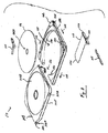
図1Aおよび図1Bはこの発明に係るカートリッジ10の斜視図である。両図に含まれるのは、好ましくはプラスチックからなる挿入部102、および、シートメタル、好ましくはステンレス鋼からなるシース104である。挿入部102を本明細書中では「プラスチック挿入部」と呼ぶが、挿入部102は、金属、セラミック、フェノール性リネン、材木、複合材料、圧縮紙または他の繊維などの他の材料からなり得ることが理解されるであろう。図1Aはカートリッジ10の上部側を示し、図1Bはカートリッジ10の底部側を示す。図2Aおよび図2Bは、それぞれカートリッジ10の上面図および底面図である。これらの図にはさらにシャッタ開口部106、シャッタ108、およびスピンドル開口部110が見られる。図2Aに示されるように、カートリッジ10に凹部193が形成される。凹部193はドライブの機構と相互に作用して、カートリッジ10がドライブに挿入された後にカートリッジ10をドライブ内に保つ。凹部193は図10Aおよび図10Bにも示される。
DESCRIPTION OF THE INVENTION FIGS . 1A and 1B are perspective views of a
図3は、底部側から見たカートリッジ10の分解図である。示されるように、シートメタルシース104は好ましくは、曲げ領域122で折り返された単一のシートメタル片からなり、曲げ領域122の互いに対向する底壁部104Bおよび上壁部104Tを形成する。プラスチック挿入部102は、矢印128によって示される方向にシース104に挿入される。プラスチック挿入部102は光学データ記憶ディスク116を囲む開口部124を含み、プラスチック挿入部102の一つの端縁は、開口部124に通じる空隙126を有する。カートリッジ10が完全に組立られると、プラスチック挿入部102の空隙126はシース104の曲げ領域122に隣接する。3つのタブ130(このうち2つのみが目に見える)が、円弧形状の開口部124の端縁から半径方向内向きに突き出す。ディ
スク116はカートリッジ10の組立時にタブ130上に載っており、その後プラスチック挿入部102がシース104に挿入される。他の実施例では、メタルシースは互いに離れた壁部を含む。
FIG. 3 is an exploded view of the
シャッタ108は上壁部104Tに隣接して嵌合し、シャッタ開口部106が露出する開放位置とシャッタ開口部106が閉じられる閉鎖位置との間を動く。シャッタ108は、シートメタルをスタンピングすることによって形成される、図1Aに示される壁部104Tの凹部領域105内を摺動する。シャッタ108の内面は摩擦および磨耗を低減するためにPTFEまたは他のコーティングでコートされ得る。開放位置と閉鎖位置との間を動く際、シャッタ108はプラスチック挿入部102に形成されるレール132上を摺動する。シャッタ108の摺動部134がレール132上を摺動する。シャッタ108のカンチレバーの端のタブ136は、上壁部104Tの面に溶接される、好ましくはステンレス鋼である金属細片118の下を摺動する。
The
シャッタ108は、プラスチック挿入部102に形成されるラッチ凹部120に嵌合するラッチ114によって閉鎖位置にロックされる。シャッタ108の矩形の窓140は、カートリッジ10が外部ディスクドライブに挿入されると、ディスクドライブの特徴に係合してシャッタ108を閉鎖位置から開放位置へ引くよう設計される。この実施例では、カートリッジ10は矢印142の方向にディスクドライブに挿入され、ユーザがカートリッジ10を手で掴むのを助けるために一対のギザギザの領域144がプラスチック挿入部102に設けられる。第2のギザギザの領域144はプラスチック挿入部102の上方角近傍に位置しており、図3では目に見えない。
The
図4Aおよび図4Bはプラスチック挿入部102およびシャッタ108を示しており、シャッタ108はそれぞれ閉鎖位置および開放位置にある。図5および図6は、それぞれラッチ114およびシャッタ108の詳細図である。図4Aおよび図4Bに示されるように、ラッチ114はラッチ凹部120内に静止している。ラッチ114は好ましくは成形プラスチック、好ましくはナイロンからなる。図4A、図4Bおよび図5に示されるように、ラッチ114は、凹部120の対応する円筒形の壁と接触する円筒形の表面148を有し、これによってラッチ114の本体150が、円筒形の表面148によって規定される垂直軸を中心に凹部120内で回転可能となる。ラッチ114はまたばねアーム152を含み、これは曲がるのに十分薄く作られ、かつラッチ114を凹部120内に配置するとばねアーム152が矢印154の方向に若干曲がるように本体150に対して角度を付けられており、これによりラッチ114を図4Aおよび図4Bに示される伸ばした位置で維持することができる。この構造を用いれば、ロータリーシャフトまたはピンによってラッチ114をプラスチック挿入部102および/またはシース104に接続させる必要がない。部品が非常に小型であらねばならない際にこれは重要な特徴である。
4A and 4B show the
ラッチ114はまた、シャッタ108が閉鎖位置にあるときにシャッタ108のタブ158と噛み合うノッチ156を含む。シャッタ108が閉じられると、ばねアーム152によって与えられるばね力が、タブ158がノッチ156に係合したままであるようにラッチ114の本体150を回転させる。典型的にカートリッジ10をディスクドライブに挿入することによってシャッタ108を開けるときは、ディスクドライブの外部特徴(図示せず)が傾斜面160に接して摺動し、これによってばねアーム152の力に対抗し、ノッチ156がプラスチック挿入部102内へ後退してタブ158から外れるように本体150を強制的に回転させる。ノッチ156とタブ158とが離されると、外部特徴(図示せず)が窓140に係合し、シャッタ108を閉鎖位置から開放位置へ動かす。カートリッジ10をディスクドライブから取り出すと、外部特徴はシャッタ108を開放位置から閉鎖位置へ摺動させ、タブ158は傾斜面162(図5参照)上を摺動して、タブ158が傾斜面162を通過して再びノッチ156内に静止するまで再びラッチ114を後退
させる。
The
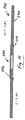
図8はシートメタルシース104を取外したカートリッジ10の上面図であり、凹部120内のラッチ114の位置およびラッチ114の回転軸190の場所を示している。図8にはまた、ノッチ156とタブ158との係合も示される。
FIG. 8 is a top view of the
シャッタロック機能を提供する多数の他の方法があることが理解されるであろう。この発明は上述の例に限定されるものではなく、むしろシャッタを制御するための多種多様な代替的な技術を利用し得る。 It will be appreciated that there are many other ways to provide a shutter lock function. The invention is not limited to the examples described above, but rather a wide variety of alternative techniques for controlling the shutter may be utilized.
再び図3を参照して、シートメタルシース104は、上壁部104Tから突き出す金属タブ164Aおよび166Aを含む。シース104が緩んだ状況にあるとき、タブ164Aおよび166Aの端は底壁部104Bに当接する。図4Aを参照して、プラスチック挿入部102にスロット164Bおよび166Bが形成されており、タブ164Aの寸法はスロット164Bの寸法とほぼ同一であり、タブ166Aの寸法はスロット166Bの寸法とほぼ同一である。つまり、タブ164Aおよび166Aは、それぞれスロット164Bおよび166Bとピッタリと嵌合する。
Referring again to FIG. 3, the
プラスチック挿入部102およびシートメタルシース104の組立前に、ディスク116が開口部124内に配置され、タブ130上に載っている。そして壁部104Tと104Bとが若干離され、タブ164Aがスロット164B内にありタブ166Aがスロット166B内にあるようになるまでプラスチック挿入部102がシース104に挿入される。シース104は好ましくはステンレス鋼などの弾性材料からなるため、壁部104Tおよび104Bはこれを実行可能とするのに十分に曲がることができるので、曲がってその後当初の形状へ戻ることができる。この時点で、タブ164Aおよび166Aの端は壁部104Bにスポット溶接される。これにより非常に剛性の構造が生成される。
Prior to assembly of the
カートリッジ10の強度を高めるため、シース104はまた、曲げ領域122から横方向に延在するタブ168Aおよび170Aを含む。タブ168Aは図3に示されており、タブ170Aは曲げ領域122の対向端において同様の態様で延在していることが理解されるであろう。図4Aを参照して、プラスチック挿入部は、空隙126の対向側に形成される隙間168Bおよび170Bを有する。上述のようにプラスチック挿入部102がシース104に挿入されると、タブ168Aが隙間168Bに嵌合し、タブ170Aが隙間170Bに嵌合する。この構成により、空隙126の近傍において付加的な構造的安定性がもたらされる。
To increase the strength of the
ディスク116は、通常のCDドライブで利用されるのと同様の、あごのあるスナップ式のリテーナを有するスピンドルハブとともに動作するよう設計される。したがって図3に示されるように、ディスク116は中心孔116Aを有するが、ハブは有しない。カートリッジ10が完全に組立られると、ディスク116は、それぞれ壁部104Tおよび104Bの内面上に形成される、図7Aおよび図7Bに示される隆起リング180および182によって支持される。隆起リング180および182はシートメタル内にエンボス加工される。1つの実施例では隆起リング180および182の高さは0.35mmである。図9は、隆起リング180および182の場所を示すカートリッジ10の断面図である。示されるように、隆起リング180はスピンドル開口部110の周縁に位置する。図9にはまた、シートメタルシース104の底壁部104B内のスタンピングされた凹部に嵌合する紙ラベル192も示される。これはカートリッジ10の「ラベル側」と呼ばれることもある。
The
1つの実施例では、カートリッジ10は、たとえば、PDA内のコンパクトフラッシュ
(登録商標)スロットに嵌合するディスクドライブに嵌合するよう設計される。そのようなカートリッジの厚みは2.0mmに目標付けられ得る。ディスク116の直径を32mmとし、厚みを0.7mmとして、約1.3mmをカートリッジの残余に残しておいてもよい。上壁部104Tおよびシャッタ108がディスク116の一方側にあり、底壁部104Bがディスク116の他方側にある。シース104およびシャッタ108が厚み0.15mmのステンレス鋼シートからなる場合、これらの構成要素の総厚みは0.45mmになる。また、シャッタ108と上壁部104Tとの間に約.025mmの間隙があり、厚み0.100mmのラベルがカートリッジの一方側に配置されて、合計が0.575mmに増加する可能性もある。これにより、ディスク116と壁部104Tおよび104Bの内面との間の間隙に0.725mm(1.3−0.575)が残されるか、またはディスク116の各側に0.3625mmが残される。±0.05mmの垂直方向のディスクランナウトを前提として、特徴サイズおよび位置公差ならびにスピンドルおよびディスク−スピンドルインターフェイスに起因するいずれのランナウトについても0.3125mmの間隙が残る。
In one embodiment,
これと比較して、カートリッジの上壁および底壁がプラスチックからなる場合、安定した構造であるためには、シートメタルに対する0.15mmの代わりに約0.32mmのオーダの最小限の厚みが必要となる(シャッタの厚みは同一のままである)。また、プラスチックの壁の平坦性のばらつきのために0.07mmを見込んでおく必要がある。したがって、ディスクの各側における0.3125mmの間隙は0.0725mmに減少させられることになる(0.3125−((0.32−0.15)+0.07)))。これは、スピンドルに起因するランナウトなどの残りの変数に対応するには小さすぎる。 In contrast, if the top and bottom walls of the cartridge are made of plastic, a minimum thickness of the order of about 0.32 mm is required instead of 0.15 mm for the sheet metal in order to have a stable structure (The thickness of the shutter remains the same). In addition, it is necessary to allow 0.07 mm due to variations in flatness of the plastic wall. Thus, the 0.3125 mm gap on each side of the disk will be reduced to 0.0725 mm (0.3125 − ((0.32−0.15) +0.07))). This is too small to accommodate the remaining variables such as runout due to the spindle.
本発明に係る代替的な実施例が、カートリッジ20を図示する図11〜図15に示される。 An alternative embodiment according to the present invention is shown in FIGS.
図11Aおよび図11Bはカートリッジ20の2つの分解図であり、図11Aは上から見た図であり、図11Bは下から見た図である。カートリッジ20は、典型的にプラスチックからなるシェル200、シートメタルからなるカバープレート202、シャッタ204、光学データ記憶ディスク組品206、およびラッチ208を含む。
11A and 11B are two exploded views of the
カートリッジ20の詳細な構造および組立方法を説明する。
図12Aおよび図12Bは、それぞれ外側および内側からのシェル200を図示している。シェル200はレンズ等級ポリカーボネートからなり、標準的な射出成形プロセスによって製造され得る。1つの実施例ではシェル200の横方向の寸法は約36mm×36mmであり、シェル200の厚みは約3mmである。シェル200は前縁217および後縁218を有する。後縁218は弓形形状(たとえば半径≒78mm)であり、前縁217および側縁は一般に直線的である。
The detailed structure and assembly method of the
12A and 12B illustrate the
図12Aに示されるように、シェル200の外側は、シェル200の周囲部分に対して0.2mmだけ凹み得る浅い凹部214および216を有する。以下に説明するように、シャッタ204の一部は凹部214内を摺動し、凹部216は映画ラベルなどの印刷物を保持するのに使用することができる。アライメントホール222Aおよび222Bはディスクドライブ内の対応するアライメントポスト(図示せず)の上に嵌合し、確実にカートリッジ20がドライブ内に正確に位置決めされるようにする。後縁218の近傍には、幅が約0.4mmで0.6mmだけ離された3つの長手方向の溝219があり、カートリッジ20をディスクドライブに挿入する際にユーザがカートリッジ20を掴むのを助ける。
As shown in FIG. 12A, the outside of the
図12Bに示されるように、シェル200の内部は、床201、ならびに4つの内壁211A〜211Dおよび4つの外周壁212A〜212Dを含む複数の横方向の壁を含む
。外周壁212A〜212Dの各々は、シェル200の外周の一辺に沿って走る。内壁211A〜211Dの各々は全体として円弧形状に形成される。床201、内壁211A〜211Dおよび外周壁212A〜212Dの一部はともに、ディスク組品206を保持するのに用いられる全体として円形のディスクキャビティ210を規定する。さらに以下に説明するように、シェル200の内側から見ると、外周壁212Dは外周壁212A〜212Cよりも厚い。シェル200の1つの角では、内壁211Aならびに外周壁212Aおよび212Dの一部が、ラッチ208を保持するのに用いられるラッチキャビティ207を形成する。ラッチキャビティ207内、ならびに内壁211B〜211Dおよび外周壁212A〜212Dによって形成される3つのキャビティ内に位置する5つの組立ポスト213を用いて、カバープレート202をシェル200に取付ける。
As shown in FIG. 12B, the interior of the
図12Aおよび12Bから明白なようにシェル200は好ましくはモノリシックである、すなわち、シェル200は好ましくは単一の一体化した材料片で形成される。シェル200は好ましくはプラスチックからなるが、金属などの他の材料を使用してシェル200を作製してもよい。
As is apparent from FIGS. 12A and 12B, the
図12Cは、シェル200の前縁217の周りの領域の詳細図である。外周壁212Bに凹部209が形成される。凹部209はディスクドライブの爪(図示せず)と相互に作用して、カートリッジ20が完全に装填された際にカートリッジ20をドライブ内に保つ。
FIG. 12C is a detailed view of the area around the
図12Dは、図12Bの断面線12D−12Dでとられた、ラッチキャビティ207内の組立ポスト213の断面図である。示されるように、組立ポスト213は内壁211Aおよび外周壁212Aよりも若干上方の高さまで上向きに延在する。以下に説明するように、組立ポスト213内のこの追加的な材料は溶融されて、カバープレート202をシェル200に取付けるためにマッシュルームキャップを形成する。
12D is a cross-sectional view of the
図13はカバープレート202の上面図である。カバープレート202は厚みが0.15mmのステンレス鋼シートからなり得る。ステンレス鋼シートをスタンピングして凹部230および凹部230内のシャッタ窓232を形成する。凹部230は、カバープレート202の周囲部分に対して、たとえば0.2mmだけ凹み得る。以下に説明するように、シャッタ204の一部は凹部230内を前後に摺動して窓232を開閉する。この動きによって交互に、ディスク組品206を損傷から保護し、ディスク組品206に記憶されるデータを外部の光学ピックアップユニット(図示せず)によって読取可能とする。
FIG. 13 is a top view of the
カバープレート202の角近傍には5つの凹型孔234がある。図14Aおよび図14Bは、それぞれ図13の断面線14A−14Aおよび14B−14Bでとられた、凹型孔234のうち2つの断面図である。示されるように、凹型孔234の端縁は、カバープレート202の周囲表面に対して(たとえば0.15mmだけ)凹んでいる。
There are five
カバープレート202は、凹部230および孔234の周りの凹部以外は平面である。他の実施例では、凹部230および/または孔234の周りの凹部を省略してもよい。
The
カバープレート202のノッチ238Aおよび238Bはシェル200のアライメントホール222Aおよび222Bに沿って整列し、ディスクドライブのアライメントポスト(図示せず)を収容する。
The notches 238A and 238B of the
図15A〜図15Dはシャッタ204の構造を図示する。図15Cから明らかなように、シャッタ204はU字形である。シャッタ204は、たとえば、厚みが0.13mmのステンレス鋼のシートからなり得る。カートリッジ20が組立てられると、シャッタ20
4は本質的にカートリッジ20の1つの端縁に巻き付いてカートリッジ20の当該端縁に沿って摺動し、カバープレート202のシャッタ窓を交互に開閉する。図15Cに示されるように、シャッタ204は、端縁壁228によってともに接続される保護フラップ224および締付けフラップ226を含む。図15Aは保護フラップ224の側からのシャッタ204を示し、図15Bは締付けフラップ226の側からのシャッタ204を示し、図15Dは端縁壁228の側からのシャッタ204を示す。図15Bに示されるように、締付けフラップ226をスタンピングしてレールタブ226Aおよび226Bならびにラッチタブ226Cを形成する。たとえば、レールタブ226Aおよび226Bの幅は1.25mmに等しく、ラッチタブ226Cの幅は0.7mmに等しくてもよい。レールタブ226Aおよび226Bならびにラッチタブ226Cの長さは0.43mmでもよい。ラッチタブ226Cは、端縁壁228に対して約20°の角度αで傾斜している。
15A-15D illustrate the structure of the
4 essentially wraps around one edge of the
図15Dに示されるように、端縁壁228に開口部229が形成される。開口部229はディスクドライブ内の特徴に係合し、カートリッジ20がディスクドライブに挿入される、およびディスクドライブから引き抜かれる際にシャッタ204を開閉するのを助ける。
As shown in FIG. 15D, an
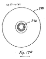
図16は、光学ディスク240および環状の磁気リテーナリング242を含むディスク組品206の断面図である。図17Aおよび図17Bは、それぞれディスク240のデータ側および非データ側からの上面図である。図16を参照して、光学ディスク240の非データ側は上向きに示され、光学ディスク240のデータ側は下向きに示されている。光学ディスク240は直径が32mmで厚みが0.55mmであってもよく、直径が4.010〜4.022mmであり得る中心孔244を有する。磁気リテーナリング242は、中心孔244と同心円状に光学ディスク240の非データ側に貼付けられる。
FIG. 16 is a cross-sectional view of a
図17Aを参照して、光学ディスク240のデータ領域250が示される。データ領域250の内周の半径は6.88mmであり、データ領域250の外周の半径は14.8mmであり得る。バーコード領域/内径グラフィックス(BCA/IRG)領域256は、半径5mmから半径5.8mmまで延在する。
Referring to FIG. 17A, the
図18Aは、中心孔244の周りの領域内の光学ディスク240の断面図である。非データ(上部)側では、深さが0.05mmであり得る浅い凹部245が、磁気リテーナリング242が貼付けによって光学ディスク240に取付けられる領域内に形成される。深さが0.2mmで幅が1mmであり得る円形の周縁凹部246を形成して、内向きに流れ得る如何なる貼付剤も捉え、これによって貼付剤が中心孔244に入ることを防止する。周辺凹部246は直径が6mmであり得る。
FIG. 18A is a cross-sectional view of the
光学ディスク240のデータ(底部)側では、円形の隆起リム248が中心孔244と同心円状に形成され、ディスク組品206がディスクキャビティ210内で囲まれた際に光学ディスク240のデータ領域250がカバープレート202と接触するのを防止する。リム248は高さが0.25であり、幅が1mmであり、直径が9mmであり得る。隆起リム248はまた、被覆層スピンコーティングプロセスで用いられる液体ラッカーが中心孔244に流れ込むのを防止するため、ディスク被覆層製造プロセスにおいても有用である。非データ側がディスクキャビティ210の床201上に載っている状態でディスク組品206が静止位置にあるとき、隆起リム248とカバープレート202の内面との間の間隙は約0.35mmである。
On the data (bottom) side of the
リム248のすぐ外側にはスタンパーホルダ特徴252がある。凹部245、周縁凹部246、リム248およびスタンパーホルダ特徴252は、光学ディスク240が成形される際に形成される。光学ディスク240は好ましくはポリカーボネートからなり、公知
の射出成形プロセスで形成される。DVDディスクの製造に用いられる標準的な成形プロセスを用いて光学ディスク240を製造してもよい。
Immediately outside the
カートリッジ20の厚みは2.8mmに目標付けられ得る。光学ディスク240の直径を32mmとし、最大の厚み(磁気リテーナリング242を含む)を0.9mmとして、約1.9mmをカートリッジ20の残余に残しておいてもよい。
The thickness of the
図18Bは光学ディスク240の端縁近傍の断面図である。示されるように、光学ディスク240の端縁は5〜7度の抜き勾配dを持って形成されており、成形されたディスクを変形させることなくディスクを鋳型から排出することができる。
FIG. 18B is a cross-sectional view of the vicinity of the edge of the
図19A、図19Bおよび図19Cは磁気リテーナリング242を示す図である。磁気リテーナリング242の中心孔の直径は4.5mmであり、磁気リテーナリング242の外周の直径は9.2mmであり得る。磁気リテーナリング242は、厚みが0.2mmのステンレス鋼のシート430または他の磁気金属から形成され得る。
19A, 19B, and 19C are views showing the
磁気リテーナリング242は、磁気リテーナリング242を装着ポスト上に支持し、Dymax 3013−Tなどの紫外線(UV)硬化可能接着剤を点状に磁気リテーナリング242上へ配置することによって、光学ディスク240に取付けられ得る。データ側を上向きにして磁気リテーナリング242を凹部245に嵌合させた状態で、光学ディスク240を磁気リテーナリング242上に配置する。光学ディスク240上に垂直方向の頂部負荷(たとえば5〜7oz)を配置し、UV光を垂直方向の頂部負荷および中心孔244を貫通させて導いて接着剤を硬化させる。垂直方向の頂部負荷は環状で、5〜8mmのスルーホールを有しているので、UV光ガイドを用いることができる。
The
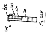
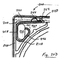
図20Aおよび図20Cは、それぞれラッチ208の上面図および底面図である。図20Bはラッチ208の側面図である。ラッチ208はポリプロピレンなどの可撓性プラスチックからなり得る。ラッチ208はアーム部分256、258および260を含み、これらの各々は幅が1.5mmで厚みが0.5mmの細片から形成され得る。アーム部分258の長さは3.4mmで、アーム部分260の長さは7.2mmであり得る。アーム部分256と258との間の角度aは36°であり、アーム部分258と260との間の角度bは105°であり得る。弧部分261はアーム部分256の端に位置する。
20A and 20C are a top view and a bottom view of
フック262および解放カム264がアーム部分260の一方側から延在する。フック262は一方側にカム表面265および対向側に掴み表面267を有する。カム表面265はアーム部分260の長手方向に対して105°の角度を付けられていてもよく、掴み表面267はアーム部分260の長手方向に対してほとんど垂直である。解放カム264は前縁266および後縁268を有する。前縁266は、アーム部分260の長手方向に対して約75°の角度を付けられている。フック262と解放カム264との間にノッチ263が形成される。図20Bからわかるように、フック262および解放カム264はアーム部分256、258および260ほど厚くない。
A
図20Dは、ラッチ208がどのようにラッチキャビティ207内に位置決めされるのかを示す(図12Bも参照)。弧部分261ならびにアーム部分256および258は組立ポスト213の1つを囲み、アーム部分258は外周壁212Aに接して静止している。フック262および解放カム264は外周壁212Dの窓を貫通し、シェル200の対向側部の外周壁212Dに形成されるシャッタレール溝220内へ延在する。ラッチキャビティ207内に組立てられると、ラッチ208は曲がった状況にある。図20Eは、シャッタレール溝220内へ突き出すフック262および解放カム264のさらに詳細な図である。
FIG. 20D shows how the
カートリッジ20は、ラッチ208をキャビティ207内へ配置し、ディスク組品206をディスクキャビティ210内へ配置し、組立ポスト213を用いてカバープレート202をシェル200へ取付け、かつシャッタ204をカートリッジ200の外側に付けることによって組立てられる。モノリシックのシェル、およびシェルの一方側に取付けられるカバープレートを使用することにより、カートリッジの作製が大幅に簡略化される。これらのステップをより詳細に説明する。
The
まず、弧部分261ならびにアーム部分256および258がラッチキャビティ207内に位置する組立ポスト213の周りにある状態で図20Dに示される態様でラッチ208をラッチキャビティ207内に配置する。アーム部分256は内壁211Aに当接し、アーム部分258は外周壁212Aに当接し、アーム部分260は外周壁212Dに当接する。ラッチ208の動作を以下に説明する。
First, the
次に、データ側を上向きにして、ディスク組品206をディスクキャビティ210内に配置する。リテーナリング242はディスクキャビティ210の床201上に載っている。光学ディスク240の外側端縁と内壁211A〜211Dとの間の間隙は1.05mmであり得る。
Next, the
ラッチ208がラッチキャビティ207内にありディスク組品206がディスクキャビティ210内にある状態で、内壁211A〜211Dおよび外周壁212A〜212Dの上面上にカバープレート202を配置し、ラッチキャビティ207およびディスクキャビティ210を閉じる。好ましくは、カバープレート202の横方向の寸法はシェル200の横方向の寸法よりも若干小さく、外周壁212A〜212Dの上面の内側端縁上に浅い凹部が形成される。カバープレート202はこの凹部内に着座する。組立ポスト213は、カバープレート202の凹型孔234を通って約0.2mmだけ突出するように位置決めされる。そして、はんだごてまたは熱杭工具を用いて組立ポスト213のプラスチック先端部を溶融し、これにより凹型孔234の上方にマッシュルーム形状のキャップを形成する。このように、組立ポスト213の先端部上のマッシュルームキャップによってカバープレート202がシェル200に取付けられる。溶融したプラスチックを孔234の周りの凹部内に保ち、カバープレート202の側でカートリッジ20の実質的に平坦な外面を設けてもよい。
With the
組立プロセスの最後のステップは、シェル200およびカバープレート202の外側にシャッタ204を装着することである。シャッタ204は弾性シートメタルからなるため、シャッタ204を永久に変形させることなく保護フラップ224と締付けフラップ226とを若干離すことができる。シャッタ204の端縁壁228は、シェル200の端縁の周りに嵌合するのにちょうどよい幅であるよう形成される。保護フラップ224がカバープレート202の凹部230内にあり、締付けフラップがシェル200の凹部214内にある状態でシャッタ204が装着される。
The final step in the assembly process is to mount the
図12Aに戻って、シャッタレール溝220は前縁217で始まり、シェル220の後縁218までの距離の一部に延在する。シャッタレール溝220は外周壁212Dに形成され、上述のように、外周壁212Dは外周壁212A〜212Cよりも厚く形成されて溝220を収容する。図21は、図12Aに示される切断線21−21でとられた外周壁212Dの断面図であり、シャッタ204は所定の位置にある。シャッタ204は、レールタブ226Aおよび226Bならびにラッチタブ226Cがシャッタレール溝220内を自由に摺動できるよう装着される。レールタブ226Aおよび226Bは、シャッタ204が最小限のラッキングまたは「がたつき」でシェル200の端縁に沿って自由に摺動可能となるシャッタ204の場所に形成される。
Returning to FIG. 12A, the
レールタブ226Aおよび226Bならびにラッチタブ226Cが溝220内にある状態で、シャッタ204がカートリッジ20上へ装着される。シャッタ204が溝220に沿って前後に摺動すると、保護フラップがカバープレート202の凹部230内を摺動し、窓232を交互に開閉する。窓232が開くと、中心孔244およびデータ領域250の半径部分が露出し、これにより中心孔244がスピンドルモータによって係合され、データ領域250からデータを読出すことが可能となる。同様に、シャッタ204が前後に摺動すると、締付けフラップ226がシェル200の凹部214内を前後に摺動する。
The
上述のように、溝220をラッチキャビティ207から離す窓が溝220の側部に形成される。窓は、シェル200の床201からの行程の一部分しか延在しない。フック262および解放カム264はこの窓を貫通して溝220内へ突出する。図20Bに示されるように、フック262および解放カム264はラッチ208の全厚みにわたって延在しない。このためフック262および解放カム264が窓を貫通して延在することが可能となり、ラッチ208をラッチキャビティ207内に安定して位置決めする助けとなる。
As described above, a window is formed on the side of
シャッタ204の装着を完了するため、シャッタ204をラッチ208の方向にシェル200の端縁に沿って摺動させる。シャッタ204が溝220内を摺動すると、ラッチタブ226C(図15Bに示す)もまた溝220に沿って動く。保護フラップ224が窓232を覆う位置にシャッタが到達すると、ラッチタブ226Cがフック262のカム表面265と接触する。これは図27Aに示される。これによってラッチ208が若干曲がり、フック262を窓内へ押し戻す。図27Bに示されるように、ラッチタブ226Cがフック262を過ぎると、ラッチ208は当初の構成に戻り、ラッチタブ226Cはフック262の掴み表面267によってノッチ263内で拘束される。これにより、窓232が閉じられる位置でシャッタ204がロックされ、光学ディスク240のデータ領域250を損傷から保護する。
To complete the mounting of the
図22はディスクドライブのカートリッジトレー30に挿入されているカートリッジ20の全体図である。図23A〜図23Cはカートリッジトレー30の領域50の詳細図である。
FIG. 22 is an overall view of the
図23Aは領域50の上面図であり、カートリッジ20がカートリッジトレー30に挿入された際にシャッタ204を解放するための機構を示している。図23Bおよび図23Cは領域50の斜視図である。カートリッジトレー30は、シャッタレール溝220内へ下向きに突き出す形態、この実施例ではブレード302、を含む。カートリッジ20がカートリッジトレー30に短い距離だけ挿入されると、ブレード302が解放カム264の前縁266と接触し、解放カム264およびフック262を窓内へ押し戻す。図28A参照。これによりラッチタブ226Cが解放され、シャッタ204がカートリッジ20の端縁に沿って自由に摺動できるようになる。図28B参照。その後すぐに、ブレード302はシャッタ204の端縁225に当接し、ほぼ同時期にカートリッジトレー30のばね仕掛けのシャッタ挿入部304がシャッタ204の端縁壁228の開口部229に係合する。ユーザがカートリッジ20をカートリッジトレー30内へ摺動させ続けると、ブレード302がシャッタ204を静止して保持し、このためシャッタ204がカートリッジ20の端縁に沿って摺動してカバープレート202の窓232を開ける。カートリッジ20がカートリッジトレー30に完全に挿入されると、ある形態のディスクドライブ(図示せず)が凹部209(図12C)に係合し、カートリッジ20をカートリッジトレー30内に安定して保持する。
FIG. 23A is a top view of the region 50 and shows a mechanism for releasing the
ユーザがディスクドライブからカートリッジ20を取外すことを望む場合、ユーザは、そのディスクドライブを凹部209から後退させるディスクドライブのボタンを押す。デ
ィスクドライブのばね機構はカートリッジ20をカートリッジトレー30から部分的に押し出し、後縁218に隣接するカートリッジの一部を露出させる。ユーザがカートリッジトレー30からカートリッジ20を手動で取外すと、シャッタ204が完全に閉じられてフック262によって係合するまで、シャッタ挿入部304はシャッタ204の開口部229内に留まる。そしてユーザがディスクドライブからカートリッジ20を取外し続けると、シャッタ挿入部304は開口部229から持ち上がる。
If the user desires to remove the
図24〜図26は、スピンドルモータシャフト306がどのようにディスク組品206の中心孔244に係合するかを示す破断図である。図24は、このプロセス中に向いているであろう向きのカートリッジ20を示す図であり、シェル200は取外されている。図25はディスク組品206を取外した同様の図である。図26は、カートリッジがディスクドライブに完全に装填されたときのカートリッジ20の下側からの図である。
FIGS. 24-26 are cutaway views showing how the
図25に示されるように、スピンドルモータシャフト306は、スピンドルモータシャフト306の突出端部309から凹んでいる環状の締付けマグネット305を含む。締付けマグネット305はNiFeまたはNiCrFeなどの永久磁石材料からなり得る。図24に示すように、カートリッジ20がディスクドライブに完全に挿入されると、スピンドルモータシャフト306が上向きに動いて突出端部309を中心孔244に挿入する。突出端部309のテーパー表面307は、突出端部309を中心孔244内へ導くのを助ける。中心孔244の直径は4.010〜4.022mmでもよく、突出端部309に対して公差が厳しい。突出端部309が中心孔244に入ると、締付け磁石305が、上述のように光学ディスク240の非データ側に貼付けられている磁気リテーナリング242を引き付ける、または引張る。ディスクドライブの2つのアライメントポスト(図示せず)がアライメントホール222Aおよび222Bに嵌合し、確実にカートリッジ20が正確にかつ繰返してディスクドライブ内に位置決めされるようにする。
As shown in FIG. 25, the
上述のこの発明の実施例は例示的なものであり限定的なものではない。この発明の広い範囲内の多くの代替的な実施例が当業者にとって明らかになるであろう。 The above-described embodiments of the present invention are illustrative and not limiting. Many alternative embodiments within the broad scope of this invention will be apparent to those skilled in the art.
Claims (17)
ディスクキャビティを有するモノリシックのプラスチックシェルを備え、前記ディスクキャビティは床および横方向の壁によって境界をつけられ、前記横方向の壁は前記ディスクキャビティを横方向に取囲み、前記カートリッジはさらに
前記ディスクキャビティ内に位置する光学データ記憶ディスクと、
前記シェルに取付けられるシートメタルカバーとを備え、前記シートメタルカバーは前記ディスクキャビティを囲むように前記横方向の壁の上面に当接し、前記シートメタルカバーにシャッタ窓が形成され、前記カートリッジはさらに
前記カートリッジの端縁に巻き付けられるシャッタを備え、前記シャッタはカバープレートに隣接する保護フラップを備え、前記シャッタは、前記光学ディスクの一部が前記シャッタ窓から露出する開放位置と、前記保護フラップが前記シャッタ窓の上に横たわって前記光学ディスクを隠す閉鎖位置との間で前記カートリッジの前記端縁に沿って摺動可能である、カートリッジ。 An optical data storage disk cartridge,
A monolithic plastic shell having a disk cavity, the disk cavity being bounded by a floor and a lateral wall, the lateral wall laterally surrounding the disk cavity, and the cartridge further comprising the disk cavity An optical data storage disk located within;
A sheet metal cover attached to the shell, wherein the sheet metal cover is in contact with an upper surface of the lateral wall so as to surround the disk cavity, a shutter window is formed in the sheet metal cover, and the cartridge further includes A shutter wound around an edge of the cartridge; the shutter includes a protective flap adjacent to a cover plate; the shutter includes an open position where a part of the optical disk is exposed from the shutter window; and the protective flap A cartridge slidable along the edge of the cartridge between a closed position lying on the shutter window and concealing the optical disk.
プラスチックシェルを提供するステップを備え、前記プラスチックシェルはディスクキャビティを有し、前記ディスクキャビティは床および横方向の壁によって境界をつけられ、前記横方向の壁は前記ディスクキャビティを横方向に取囲み、前記プラスチックシェルはさらに複数のプラスチック組立ポストを備え、前記方法はさらに
複数の孔を有するシートメタルカバーシートを提供するステップと、
前記ディスクキャビティ内に光学データ記憶ディスクを配置するステップと、
前記ディスクキャビティ内の前記光学データ記憶ディスクを囲むように前記シートメタルカバーシートを前記プラスチックシェルに隣接して配置するステップとを備え、前記組立ポストの各々は前記孔の1つを貫通して突き出しており、前記方法はさらに
シートメタルカバーを前記プラスチックシェルに対して保持するキャップを形成するために前記組立ポストの各々の端部を加熱するステップを備える、方法。 A method for producing a cartridge for an optical data storage disk comprising:
Providing a plastic shell, the plastic shell having a disk cavity, the disk cavity being bounded by a floor and a lateral wall, the lateral wall laterally surrounding the disk cavity The plastic shell further comprises a plurality of plastic assembly posts, the method further comprising providing a sheet metal cover sheet having a plurality of holes;
Placing an optical data storage disk in the disk cavity;
Placing the sheet metal cover sheet adjacent to the plastic shell so as to surround the optical data storage disk in the disk cavity, each of the assembly posts projecting through one of the holes. The method further comprises heating each end of the assembly post to form a cap that holds a sheet metal cover against the plastic shell.
Applications Claiming Priority (2)
| Application Number | Priority Date | Filing Date | Title |
|---|---|---|---|
| US11/209,553 US7603681B2 (en) | 2003-04-25 | 2005-08-22 | Cartridge for miniature optical data storage disc |
| PCT/US2006/032216 WO2007058690A1 (en) | 2005-08-22 | 2006-08-18 | Cartridge for miniature optical data storage disc |
Publications (2)
| Publication Number | Publication Date |
|---|---|
| JP2009505328A true JP2009505328A (en) | 2009-02-05 |
| JP2009505328A5 JP2009505328A5 (en) | 2009-10-08 |
Family
ID=38048952
Family Applications (1)
| Application Number | Title | Priority Date | Filing Date |
|---|---|---|---|
| JP2008528000A Pending JP2009505328A (en) | 2005-08-22 | 2006-08-18 | Compact optical data storage cartridge |
Country Status (7)
| Country | Link |
|---|---|
| US (1) | US7603681B2 (en) |
| EP (1) | EP1917663A4 (en) |
| JP (1) | JP2009505328A (en) |
| KR (1) | KR20080036643A (en) |
| CN (1) | CN101283411A (en) |
| TW (1) | TW200709183A (en) |
| WO (1) | WO2007058690A1 (en) |
Families Citing this family (7)
| Publication number | Priority date | Publication date | Assignee | Title |
|---|---|---|---|---|
| US7013476B2 (en) | 2003-04-25 | 2006-03-14 | Vmedia Research, Inc. | Cartridge for miniature optical data storage disc |
| US8177129B2 (en) * | 2004-02-17 | 2012-05-15 | Timothy D. Larin | Interactive multimedia smart affinity card with flash memory |
| US7213749B2 (en) * | 2004-02-17 | 2007-05-08 | R&R Card Systems, Inc. | Interactive multimedia smart affinity card |
| US7983139B2 (en) * | 2007-11-30 | 2011-07-19 | Vmedia Research, Inc. | Small form factor optical data storage disc and cartridge |
| US8315144B2 (en) * | 2004-05-13 | 2012-11-20 | VMO Systems Inc. | Small form factor optical disc drive for use in mobile electronic device |
| JP2009283045A (en) * | 2008-05-20 | 2009-12-03 | Origin Electric Co Ltd | Substrate bonding apparatus |
| US8277919B2 (en) * | 2009-07-23 | 2012-10-02 | VMO Systems, Inc. | Reflective coating for an optical disc |
Citations (5)
| Publication number | Priority date | Publication date | Assignee | Title |
|---|---|---|---|---|
| JPH08195052A (en) * | 1995-01-19 | 1996-07-30 | Canon Inc | Cartridge for recording medium |
| WO1998047143A1 (en) * | 1997-04-17 | 1998-10-22 | Imation Corp. | Method for centering a hub in an optical disc, and an optical storage system using such disc |
| JP2001076455A (en) * | 1999-09-03 | 2001-03-23 | Sony Corp | Disk cartridge |
| JP2002050146A (en) * | 2000-08-02 | 2002-02-15 | Fuji Photo Film Co Ltd | Magnetic disk cartridge |
| JP2003500787A (en) * | 1999-05-20 | 2003-01-07 | データプレイ・インコーポレイテッド | Removable optical recording device and system |
Family Cites Families (20)
| Publication number | Priority date | Publication date | Assignee | Title |
|---|---|---|---|---|
| US5140489A (en) * | 1989-10-30 | 1992-08-18 | Eastman Kodak Company | Disk cartridge adapted for use with different disk drives |
| JPH07244951A (en) * | 1994-02-28 | 1995-09-19 | Hotsukoo Kk | Disk case |
| JPH07320359A (en) | 1994-05-20 | 1995-12-08 | Ricoh Co Ltd | Optical disc cartridge and optical disc driving apparatus |
| JPH08194977A (en) * | 1995-01-19 | 1996-07-30 | Canon Inc | Cartridge for magnetooptic recording medium |
| JP3160752B2 (en) * | 1995-08-15 | 2001-04-25 | シャープ株式会社 | Disk hub, disk cartridge and disk drive |
| JP3632805B2 (en) | 1996-11-07 | 2005-03-23 | 日立マクセル株式会社 | Disc cartridge |
| JPH1166792A (en) * | 1997-08-08 | 1999-03-09 | Sony Corp | Disk cartridge |
| TW412728B (en) * | 1998-01-21 | 2000-11-21 | Hitachi Ltd | Disk cartridge |
| US6298533B1 (en) * | 1998-12-02 | 2001-10-09 | Sony Corporation | Assembling device for disc cartridge |
| JP2001076456A (en) * | 1999-09-03 | 2001-03-23 | Sony Corp | Disk cartridge |
| JP2001076457A (en) * | 1999-09-06 | 2001-03-23 | Sony Corp | Disk cartridge |
| JP2001236755A (en) * | 2000-02-22 | 2001-08-31 | Fuji Photo Film Co Ltd | Magnetic disk cartridge |
| US6687215B1 (en) * | 2000-04-12 | 2004-02-03 | Dphi Acquisitions, Inc. | Low profile and medium protecting cartridge assembly |
| JP2002063778A (en) * | 2000-08-18 | 2002-02-28 | Sony Corp | Disk cartridge, method for manufacturing the same, and recording and reproducing system |
| KR100395218B1 (en) * | 2001-03-24 | 2003-08-21 | 한국과학기술연구원 | METHOD FOR MANUFACTURING BaTiO3 BASED POWDERS |
| JP2003100044A (en) * | 2001-09-21 | 2003-04-04 | Hitachi Ltd | Disk cartridge |
| CN100466092C (en) * | 2001-11-09 | 2009-03-04 | 松下电器产业株式会社 | Disc cartridge |
| US6831888B2 (en) * | 2002-03-28 | 2004-12-14 | Imation Corp. | Disk cartridge with single shutter held in multiple open positions |
| JP2004071042A (en) * | 2002-08-06 | 2004-03-04 | Fuji Photo Film Co Ltd | Disk cartridge |
| US7013476B2 (en) * | 2003-04-25 | 2006-03-14 | Vmedia Research, Inc. | Cartridge for miniature optical data storage disc |
-
2005
- 2005-08-22 US US11/209,553 patent/US7603681B2/en not_active Expired - Fee Related
-
2006
- 2006-07-26 TW TW095127404A patent/TW200709183A/en unknown
- 2006-08-18 WO PCT/US2006/032216 patent/WO2007058690A1/en active Application Filing
- 2006-08-18 EP EP06789836A patent/EP1917663A4/en not_active Withdrawn
- 2006-08-18 KR KR1020087006312A patent/KR20080036643A/en not_active Application Discontinuation
- 2006-08-18 JP JP2008528000A patent/JP2009505328A/en active Pending
- 2006-08-18 CN CNA2006800373782A patent/CN101283411A/en active Pending
Patent Citations (5)
| Publication number | Priority date | Publication date | Assignee | Title |
|---|---|---|---|---|
| JPH08195052A (en) * | 1995-01-19 | 1996-07-30 | Canon Inc | Cartridge for recording medium |
| WO1998047143A1 (en) * | 1997-04-17 | 1998-10-22 | Imation Corp. | Method for centering a hub in an optical disc, and an optical storage system using such disc |
| JP2003500787A (en) * | 1999-05-20 | 2003-01-07 | データプレイ・インコーポレイテッド | Removable optical recording device and system |
| JP2001076455A (en) * | 1999-09-03 | 2001-03-23 | Sony Corp | Disk cartridge |
| JP2002050146A (en) * | 2000-08-02 | 2002-02-15 | Fuji Photo Film Co Ltd | Magnetic disk cartridge |
Also Published As
| Publication number | Publication date |
|---|---|
| EP1917663A4 (en) | 2011-04-20 |
| US20060048167A1 (en) | 2006-03-02 |
| KR20080036643A (en) | 2008-04-28 |
| TW200709183A (en) | 2007-03-01 |
| CN101283411A (en) | 2008-10-08 |
| US7603681B2 (en) | 2009-10-13 |
| EP1917663A1 (en) | 2008-05-07 |
| WO2007058690A1 (en) | 2007-05-24 |
Similar Documents
| Publication | Publication Date | Title |
|---|---|---|
| US7774923B2 (en) | Method of fabricating cartridge for miniature optical data storage disc | |
| JP2009505328A (en) | Compact optical data storage cartridge | |
| KR20040086501A (en) | Disc cartridge | |
| JP2005322288A (en) | Disk recording and/or reproducing device | |
| EP1049092B1 (en) | Disk cartridge | |
| JP2004312987A (en) | Spindle motor and mobile communication device using the same | |
| WO2005109422A1 (en) | Disc recorder/reproducer | |
| JP2004070981A (en) | Disk cartridge and its drive device | |
| US20060218570A1 (en) | Disk cartridge | |
| JP2005116074A (en) | Disk cartridge | |
| JP2003323774A (en) | Cartridge type recording medium having hole for centering, disk shape recording medium, cartridge, drive unit, and driving method | |
| KR200378101Y1 (en) | A opening and shutting device for case with a portable U.S.B | |
| JP3601471B2 (en) | Information recording medium cartridge | |
| US20100333120A1 (en) | Tray of an Optical Disc Drive | |
| US8510765B2 (en) | Optical disc fixing device and optical disc drive using same | |
| JP4062836B2 (en) | Floppy disk drive | |
| JP2003196944A (en) | Small sized magnetic disk cartridge | |
| JP2004071043A (en) | Disk cartridge and drive device for the same | |
| KR200237436Y1 (en) | Compact disk custody box | |
| US20060102500A1 (en) | Disc cover | |
| KR20060061510A (en) | Subminiature disk drive of manual operation type | |
| JP2002015496A (en) | Disk device | |
| JP2003319604A (en) | Disk drive apparatus and system | |
| JP2007102890A (en) | Disk device | |
| JP2003196943A (en) | Small sized magnetic disk cartridge |
Legal Events
| Date | Code | Title | Description |
|---|---|---|---|
| A521 | Request for written amendment filed |
Free format text: JAPANESE INTERMEDIATE CODE: A523 Effective date: 20090814 |
|
| A621 | Written request for application examination |
Free format text: JAPANESE INTERMEDIATE CODE: A621 Effective date: 20090814 |
|
| A521 | Request for written amendment filed |
Free format text: JAPANESE INTERMEDIATE CODE: A523 Effective date: 20090820 |
|
| A977 | Report on retrieval |
Free format text: JAPANESE INTERMEDIATE CODE: A971007 Effective date: 20100210 |
|
| A131 | Notification of reasons for refusal |
Free format text: JAPANESE INTERMEDIATE CODE: A131 Effective date: 20100223 |
|
| A601 | Written request for extension of time |
Free format text: JAPANESE INTERMEDIATE CODE: A601 Effective date: 20100521 |
|
| A602 | Written permission of extension of time |
Free format text: JAPANESE INTERMEDIATE CODE: A602 Effective date: 20100528 |
|
| A601 | Written request for extension of time |
Free format text: JAPANESE INTERMEDIATE CODE: A601 Effective date: 20100622 |
|
| A602 | Written permission of extension of time |
Free format text: JAPANESE INTERMEDIATE CODE: A602 Effective date: 20100629 |
|
| A601 | Written request for extension of time |
Free format text: JAPANESE INTERMEDIATE CODE: A601 Effective date: 20100722 |
|
| A602 | Written permission of extension of time |
Free format text: JAPANESE INTERMEDIATE CODE: A602 Effective date: 20100729 |
|
| A02 | Decision of refusal |
Free format text: JAPANESE INTERMEDIATE CODE: A02 Effective date: 20110315 |