CN101283411A - Cartridge for miniature optical data storage disc - Google Patents
Cartridge for miniature optical data storage disc Download PDFInfo
- Publication number
- CN101283411A CN101283411A CNA2006800373782A CN200680037378A CN101283411A CN 101283411 A CN101283411 A CN 101283411A CN A2006800373782 A CNA2006800373782 A CN A2006800373782A CN 200680037378 A CN200680037378 A CN 200680037378A CN 101283411 A CN101283411 A CN 101283411A
- Authority
- CN
- China
- Prior art keywords
- tray salver
- disc
- shutter
- sheet metal
- covering plate
- Prior art date
- Legal status (The legal status is an assumption and is not a legal conclusion. Google has not performed a legal analysis and makes no representation as to the accuracy of the status listed.)
- Pending
Links
- 238000013500 data storage Methods 0.000 title claims abstract description 21
- 230000003287 optical effect Effects 0.000 title claims abstract description 21
- 239000002184 metal Substances 0.000 claims abstract description 45
- 239000004033 plastic Substances 0.000 claims description 47
- 229920003023 plastic Polymers 0.000 claims description 47
- 238000004519 manufacturing process Methods 0.000 claims description 20
- 238000000034 method Methods 0.000 claims description 11
- 235000001674 Agaricus brunnescens Nutrition 0.000 claims description 6
- 238000010438 heat treatment Methods 0.000 claims 3
- 238000003780 insertion Methods 0.000 description 25
- 230000037431 insertion Effects 0.000 description 25
- 230000002093 peripheral effect Effects 0.000 description 21
- 238000005452 bending Methods 0.000 description 7
- 208000005189 Embolism Diseases 0.000 description 5
- 230000007797 corrosion Effects 0.000 description 5
- 238000005260 corrosion Methods 0.000 description 5
- 239000000463 material Substances 0.000 description 5
- 230000001681 protective effect Effects 0.000 description 5
- 238000000354 decomposition reaction Methods 0.000 description 4
- 238000005516 engineering process Methods 0.000 description 4
- 230000006870 function Effects 0.000 description 4
- 230000007246 mechanism Effects 0.000 description 4
- 230000008569 process Effects 0.000 description 4
- 239000000853 adhesive Substances 0.000 description 3
- 230000001070 adhesive effect Effects 0.000 description 3
- 230000013011 mating Effects 0.000 description 3
- 230000005540 biological transmission Effects 0.000 description 2
- 230000000694 effects Effects 0.000 description 2
- 239000003292 glue Substances 0.000 description 2
- 238000001746 injection moulding Methods 0.000 description 2
- 238000009434 installation Methods 0.000 description 2
- 230000005055 memory storage Effects 0.000 description 2
- -1 phenolic aldehyde Chemical class 0.000 description 2
- 239000004417 polycarbonate Substances 0.000 description 2
- 229920000515 polycarbonate Polymers 0.000 description 2
- 238000003825 pressing Methods 0.000 description 2
- 229910001220 stainless steel Inorganic materials 0.000 description 2
- 239000010935 stainless steel Substances 0.000 description 2
- 238000003466 welding Methods 0.000 description 2
- 241001269238 Data Species 0.000 description 1
- 229910001030 Iron–nickel alloy Inorganic materials 0.000 description 1
- 241000208202 Linaceae Species 0.000 description 1
- 235000004431 Linum usitatissimum Nutrition 0.000 description 1
- 239000004677 Nylon Substances 0.000 description 1
- 239000004743 Polypropylene Substances 0.000 description 1
- 238000004026 adhesive bonding Methods 0.000 description 1
- 230000003466 anti-cipated effect Effects 0.000 description 1
- 239000007767 bonding agent Substances 0.000 description 1
- 238000004364 calculation method Methods 0.000 description 1
- 239000011248 coating agent Substances 0.000 description 1
- 238000000576 coating method Methods 0.000 description 1
- 238000004891 communication Methods 0.000 description 1
- 230000008878 coupling Effects 0.000 description 1
- 238000010168 coupling process Methods 0.000 description 1
- 238000005859 coupling reaction Methods 0.000 description 1
- 238000011161 development Methods 0.000 description 1
- 238000007599 discharging Methods 0.000 description 1
- 238000009826 distribution Methods 0.000 description 1
- 238000004049 embossing Methods 0.000 description 1
- 230000003203 everyday effect Effects 0.000 description 1
- 239000000835 fiber Substances 0.000 description 1
- 229920002457 flexible plastic Polymers 0.000 description 1
- 230000003993 interaction Effects 0.000 description 1
- 239000007788 liquid Substances 0.000 description 1
- 238000012423 maintenance Methods 0.000 description 1
- 239000002991 molded plastic Substances 0.000 description 1
- 238000000465 moulding Methods 0.000 description 1
- 229920001778 nylon Polymers 0.000 description 1
- 239000003973 paint Substances 0.000 description 1
- 229920001155 polypropylene Polymers 0.000 description 1
- 239000004810 polytetrafluoroethylene Substances 0.000 description 1
- 229920001343 polytetrafluoroethylene Polymers 0.000 description 1
- 238000007639 printing Methods 0.000 description 1
- 238000004080 punching Methods 0.000 description 1
- 230000005855 radiation Effects 0.000 description 1
- 239000012858 resilient material Substances 0.000 description 1
- 230000000717 retained effect Effects 0.000 description 1
- 239000000523 sample Substances 0.000 description 1
- 238000007789 sealing Methods 0.000 description 1
- 238000000926 separation method Methods 0.000 description 1
- 239000007787 solid Substances 0.000 description 1
- 238000004528 spin coating Methods 0.000 description 1
- 239000012899 standard injection Substances 0.000 description 1
- 230000003068 static effect Effects 0.000 description 1
- 238000003860 storage Methods 0.000 description 1
- 230000008093 supporting effect Effects 0.000 description 1
- 229920002994 synthetic fiber Polymers 0.000 description 1
- 239000002023 wood Substances 0.000 description 1
Images


Classifications
-
- G—PHYSICS
- G11—INFORMATION STORAGE
- G11B—INFORMATION STORAGE BASED ON RELATIVE MOVEMENT BETWEEN RECORD CARRIER AND TRANSDUCER
- G11B23/00—Record carriers not specific to the method of recording or reproducing; Accessories, e.g. containers, specially adapted for co-operation with the recording or reproducing apparatus ; Intermediate mediums; Apparatus or processes specially adapted for their manufacture
- G11B23/02—Containers; Storing means both adapted to cooperate with the recording or reproducing means
- G11B23/03—Containers for flat record carriers
- G11B23/0301—Details
- G11B23/0302—Auxiliary features
-
- G—PHYSICS
- G11—INFORMATION STORAGE
- G11B—INFORMATION STORAGE BASED ON RELATIVE MOVEMENT BETWEEN RECORD CARRIER AND TRANSDUCER
- G11B23/00—Record carriers not specific to the method of recording or reproducing; Accessories, e.g. containers, specially adapted for co-operation with the recording or reproducing apparatus ; Intermediate mediums; Apparatus or processes specially adapted for their manufacture
- G11B23/02—Containers; Storing means both adapted to cooperate with the recording or reproducing means
- G11B23/03—Containers for flat record carriers
- G11B23/0301—Details
- G11B23/0308—Shutters
-
- G—PHYSICS
- G11—INFORMATION STORAGE
- G11B—INFORMATION STORAGE BASED ON RELATIVE MOVEMENT BETWEEN RECORD CARRIER AND TRANSDUCER
- G11B23/00—Record carriers not specific to the method of recording or reproducing; Accessories, e.g. containers, specially adapted for co-operation with the recording or reproducing apparatus ; Intermediate mediums; Apparatus or processes specially adapted for their manufacture
- G11B23/02—Containers; Storing means both adapted to cooperate with the recording or reproducing means
- G11B23/03—Containers for flat record carriers
- G11B23/0301—Details
- G11B23/0313—Container cases
- G11B23/0315—Materials
-
- G—PHYSICS
- G11—INFORMATION STORAGE
- G11B—INFORMATION STORAGE BASED ON RELATIVE MOVEMENT BETWEEN RECORD CARRIER AND TRANSDUCER
- G11B23/00—Record carriers not specific to the method of recording or reproducing; Accessories, e.g. containers, specially adapted for co-operation with the recording or reproducing apparatus ; Intermediate mediums; Apparatus or processes specially adapted for their manufacture
- G11B23/02—Containers; Storing means both adapted to cooperate with the recording or reproducing means
- G11B23/03—Containers for flat record carriers
- G11B23/0301—Details
- G11B23/0313—Container cases
- G11B23/0316—Constructional details, e.g. shape
-
- G—PHYSICS
- G11—INFORMATION STORAGE
- G11B—INFORMATION STORAGE BASED ON RELATIVE MOVEMENT BETWEEN RECORD CARRIER AND TRANSDUCER
- G11B23/00—Record carriers not specific to the method of recording or reproducing; Accessories, e.g. containers, specially adapted for co-operation with the recording or reproducing apparatus ; Intermediate mediums; Apparatus or processes specially adapted for their manufacture
- G11B23/02—Containers; Storing means both adapted to cooperate with the recording or reproducing means
- G11B23/03—Containers for flat record carriers
- G11B23/0326—Assembling of containers
Abstract
A cartridge for an optical data storage disc includes a monolithic shell and a sheet metal cover plate. The shell includes lateral walls and a floor that together define a cavity that holds an optical data storage disc. The cover plate is attached to the shell, with the cover plate abutting the top surfaces of the lateral walls of the shell. The optical disc is housed in the disc cavity, with the data side of the disc facing the cover plate. A sheet metal shutter is wrapped around an edge of the cartridge and is slideable between an open position, wherein a portion of the optical disc is exposed through a shutter window in the cover plate and a closed position wherein the shutter overlies the shutter window. The cartridge is very strong and is easy to fabricate. The use of sheet metal next to the data side of the optical disc allows the data on the disc to be read or recorded with a very short wavelength laser.
Description
Related application
The application is that the application number of submitting on April 25th, 2003 is No.10/423, and 097 continuation applies for that again its full content is incorporated herein by reference.The application number that this application and on April 25th, 2003 submit is No.10/423, and 701 application is relevant, and its full content is incorporated herein by reference.
Technical field
The present invention relates to mass data storage, and be particularly related to the tray salver that is used for the optical data storage disc sheet, the industrial standard storage card slot compatibility in this tray salver and the portable calculation element.
Background technology
The consumer entertainment technology is just towards the high-resolution color display direction development that is used for mobile entertainment.Little by little, the user wants their recreation is carried.Stride across that tourist and Trans-Provincial/Municipal commuter are badly in need of playing on mobile phone, PDA(Personal Digital Assistant) and pocket computer, music and video entertainment activity.Yet, with the user from they game console, home theater and the amusement that the computing machine of DVD lives through be housed compare, at present, recreation is experienced very limited, even very original.
Main problem is a data storage.The fact is that most advanced and sophisticated digital entertainment is data-intensive, and all increasing every day.Traditional small-sized " form factor ", such as CompactFlash
 Card, SD flash card, MemoryStick
TMUsually can not transmit the capacity and the price of the required every megabyte of high-quality recreation experience with the portable medium of other solid memory storage.Recorded content is very expensive and unrealistic on the high capacity solid-state memory card, and guarantees very difficulty of this content effectively.
Card, SD flash card, MemoryStick
TMUsually can not transmit the capacity and the price of the required every megabyte of high-quality recreation experience with the portable medium of other solid memory storage.Recorded content is very expensive and unrealistic on the high capacity solid-state memory card, and guarantees very difficulty of this content effectively.
To carry high-quality recreation and film for mobile subscriber's electronic installation although some scholarly forecast broadband internets insert, and also have very big obstacle to overcome.Cell phone network is designed to transmit voice communication, and transmits inefficent to Large Volume Data usually.Mobile phone connects can not have required speed and extremely unreliable, and it has frequent dead band and goes offline.Even current recreation is being sent to mobile phone, but play and the quality of game environment can't be near the quality at control desk place.
WiFi or 802.11, wireless technology is designed for data and transmits, and being increased in of WiFi focus is used for mass data is sent to the to the eye very attractive of mobile device.Internet access and e-mail applications at a plurality of users can easily be supplied by WiFi.But, the multiplayer that carries out simultaneously such as thousands of (if not words up to a million) user and high-quality video or such stream content and the interaction content of film are managed and will constitute challenge to any network.Security also is the problem of WiFi, causes the content provider to experience potential pirate activity.
And the data storage problem still can exist.For the network transmission system of feasible any kind, the user's set that moves will need to embed huge memory space, keeping big download games and movie file, and follow the tracks of player's progress in recreation.May for the Web content transmission, the most significant problem be cost.The cost that has estimated the film that transmits the DVD quality on the internet will be more than 30 dollars.
Distribution cost based on disc is quite low.More noticeablely be, the user always shows buying the needs of the higher value content on the disc, and this rise by recent DVD sale aspect is confirmed.
Be clear that that the mobile entertainment industry needs is economical, the memory technology of small-shape factor, safety, satisfies ever-increasing needs portable, the high-quality recreation experience.In addition, be anticipated that the memory storage that can carry mass data can be applied to other field, such as the pocket computer that is used for being connected with the residence trouble free service.
Summary of the invention
First embodiment according to the tray salver of this aspect comprises sheet metal sheath and the embolus of preferably being made by plastics.Sheath is preferably and is folded back on himself to be formed on the wall part on the bending area opposite side by the sheet metal manufacturing.Preferably the embolus by the plastics manufacturing is inserted in the sheath, and wall part for example is attached to each other by spot welding, to form little structural voice unit (VU).Embolus has opening, and data storage disks is placed in this opening.Disc does not preferably have wheel hub, and can be approaching by the axle of passing the opening in the sheath.One of them wall part has window and shutter (shutter), and this window allows the data area near disc, and this shutter hides window and protects disc when tray salver is not arranged in disk drives.
Use protective metal shell to allow the tray salver assembly to be produced very thin (for example 2.8mm or thinner), and do not comprise its structural intergrity.Use this structure, tray salver can be provided to the little industry standard slot that is designed for data card usually with mass data (for example 2G byte or more).An example is CompactFlash
Slot, this slot are used for many PDA other small-size computer that neutralizes.Wall part is carried out spot welding each other can carry out very apace, and without bonding agent or relevant set time.
Ideally, tray salver of the present invention is used for above-mentioned application No.10/423, the disk drives of 701 types of describing.
In the second embodiment of the present invention, tray salver comprises the monolithic housing, forms to limit the disc chamber.Housing is preferably by the plastics manufacturing.The disc chamber is the border by diapire and sidewall, and sidewall laterally surrounds the disc chamber.The optical data storage disc sheet is arranged in the disc chamber.The sheet metal covering plate is in abutting connection with the top surface of sidewall.Shutter window is formed in the covering plate, and the sheet metal shutter wraps in around the tray salver edge.Shutter comprises the protection fin of contiguous covering plate.Shutter along the edge of tray salver between open position and off-position slidably, the part of CD is exposed by shutter window in open position, protection fin overlapping shutter window in off-position is with hidden CD.
Thus, a first type surface (principal surface) and the edge of disc are surrounded by housing, and other first type surface face of disc is hidden by covering plate.
Disc is housed in the disc chamber, its data side towards covering plate and its non-data side towards housing.The shutter window that is formed in the covering plate allows the part of data area and the center pit of disc to expose.Shutter comprises the clamp fin, and this clamp fin is attached to the protection fin by edge wall.The contiguous housing of clamp fin.
Disc preferably has the magnetic retaining ring, and this ring is connected on the non-data side around the heart hole therein.Disc by this magnetic keeper by the spindle motors axle of clamp to the disk drives.
The plastics latch that is housed in the latch chamber remains on a position with shutter, and shutter blocks the window of covering plate when tray salver is not arranged in disk drives in this position.When tray salver was inserted in the disk drives, the pick-up arm in the disk drives discharged latch and allows shutter to open, and exposes the data area and the center pit of disc.
The tray salver of second embodiment manufactures not expensive comparatively speaking, and is provided for protecting firm sealing on the structure of CD.On the data side of disc, use the sheet metal covering plate of relative thin to allow optic probe unit (OPU) in the disk drives to use very short wavelength's radiation (for example 405nm blue laser) reading of data from the disc.
Description of drawings
Figure 1A and 1B are respectively the birds-eye perspective and the face upwarding view of tray salver of the present invention.
Fig. 2 A and 2B are respectively the plan view from above and the face upwarding view of tray salver of the present invention.
Fig. 3 is the decomposition view of tray salver.
Fig. 4 A and 4B be respectively illustrate shutter be in close with the open position situation under the view of plastics embolus and shutter.
Fig. 5 is the detailed view of latch.
Fig. 6 is the detailed view of shutter.
Fig. 7 A and 7B are respectively the plan view from above and the face upwarding view of protective metal shell.
Fig. 8 is the view of plastics embolus, shows disc and latch.
Fig. 9 is the sectional view of the tray salver obtained in the 9-9 cross section shown in Figure 1B.
Figure 10 A and 10B show the position of the maintenance recess on tray salver.
Figure 11 A and 11B are two decomposition views according to second embodiment of tray salver of the present invention.
Figure 12 A and 12B show the plastic casing of second embodiment.
Figure 12 C shows the part of housing.
The sectional view of Figure 12 D for obtaining at the 12D-12D of Figure 12 B transversal.
Figure 13 shows the vertical view of the covering plate among second embodiment.
The sectional view that Figure 14 A obtains for the 14A-14A transversal in Figure 13.
The sectional view that Figure 14 B obtains for the 14B-14B transversal in Figure 13.
Figure 15 A-15D shows the structure of the shutter among second embodiment.
Figure 16 is the sectional view of disc devices in a second embodiment.
Figure 17 A and 17B are respectively from the vertical view of the disc devices of data side and the observation of non-data side.
Figure 18 A and 18B are respectively the sectional view of cd centre zone and fringe region.
Figure 19 A is the vertical view of magnetic retaining ring.
Figure 19 B is the skeleton view of magnetic retaining ring.
Figure 19 C is the sectional view along magnetic retaining ring diameter.
Figure 20 A and 20C are respectively the top and bottom perspective views of the latch among second embodiment.
Figure 20 B is the side view of latch.
Figure 20 D shows the latch that is positioned in the latch chamber.
Figure 20 E is uncinus and the release cam that is projected in the shutter tracking groove.
The sectional view of the thick peripheral wall that Figure 21 obtains for 21-21 transversal in Figure 12 A.
Figure 22 is the roughly view according to the tray salver in the tray salver pallet that is inserted in the disk drives of the present invention.
Figure 23 A is the vertical view of the part of tray salver pallet, shows the mechanism that is used for discharging shutter when tray salver is inserted into the tray salver pallet.
Figure 23 B and 23C are the skeleton view of the same structure shown in Figure 23 A.
Figure 24-26 is for showing the view how the spindle motors axle engages with the center pit of disc devices.
Figure 27 A shows the latch hook of the latch tab of contact shutter when shutter close.
Figure 27 B shows the relative position of latch and latch tab when shutter is closed fully.
Figure 28 A shows when tray salver and is inserted in the driver and when making release cam by the functional part contact of disk drives, follows the tracks of uncinus and the release cam that groove withdraws from from shutter.
How the uncinus that Figure 28 B shows latch under the state shown in Figure 28 A discharges from the latch tab.
Embodiment
Figure 1A and 1B show the skeleton view according to tray salver 10 of the present invention.All show insertion section 102 and sheath 104 in two views, described insertion section is preferably by the plastics manufacturing, and described sheath is by the sheet metal manufacturing that is preferably corrosion resistant plate.Insertion section 102 will be called " plastics insertion section " in this article, although be appreciated that insertion section 102 can be by other made, such as metal, pottery, phenolic aldehyde flax (linenphenolic), wood, synthetic material, compressed paper or other fiber.Figure 1A shows the top side of tray salver 10, and Figure 1B shows the bottom side of tray salver 10.Fig. 2 A and 2B are respectively the top and bottom perspective views of tray salver 10.In addition, in three views, can see fast door opening 106, shutter 108 and axle opening 110.Shown in Fig. 2 A, recess 193 is formed in the tray salver 10.Mechanism on recess 193 and the driver interacts, and to be inserted in the driver at tray salver after tray salver 10 is remained on the driver.Recess 193 is also shown in Figure 10 A and the 10B.
Fig. 3 illustrates the decomposition view of observing from the bottom side of tray salver 10.As shown in the figure, sheet metal sheath 104 is preferably by the single piece of sheet metal manufacturing, and it is folded back onto on himself in bending area 122, forms bottom wall portion 104B and top wall portion 104T on the opposite side of bending area 122.Plastics insertion section 102 is inserted in the sheath 104 along the direction of arrow 128 indications.Plastics insertion section 102 comprises opening 124, and optical data storage disc sheet 116 is contained in this opening 124, and an edge of plastics insertion section 102 has the gap 126 of leading to opening 124.When tray salver 10 is assembled fully, the bending area 122 of the gap 126 contiguous sheaths 104 of plastics insertion section 102.Three tabs 130 (can only see wherein two) are radially inwardly outstanding from the edge of opening 124, and described opening is circular arcuation.Before plastics insertion section 102 was inserted in the sheath 104, in the process of assembling tray salver 10, disc 116 was shelved on the tab 130.In another embodiment, protective metal shell comprises wall part separated from one another.
Shutter 108 is assembled into contiguous top wall portion 104T, and moves between open position and off-position, and fast door opening 106 exposes in described open position, and fast door opening 106 is closed in described off-position.Shutter 108 wall part 104T recessed regional 105 in slide, shown in Figure 1A, this recessed portion forms by punched metal sheet.The inside surface of shutter 108 can be coated with PTFE or other coating that can reduce friction and wear and tear.In the moving between open position and off-position, shutter 108 slides on track 132, and this track is formed in the plastics insertion section 102.The slipper 134 of shutter 108 slides on track 132.In the tab that hangs the end place 136 of shutter 108 slid underneath at metal tape 118, this metal tape is preferably stainless steel and is soldered on the surface of top wall portion 104T.
Fig. 4 A and 4B show plastics insertion section 102 and shutter 108, and shutter 108 lays respectively at open position and off-position.Fig. 5 and 6 is respectively the detailed view of latch 114 and shutter 108.Shown in Fig. 4 A and 4B, latch 114 is shelved in the latch recess 120.Latch 114 preferably by the molded plastics manufacturing, is preferably nylon.Shown in Fig. 4 A, 4B and 5, latch 114 has cylindrical surface 148, and the respective cylindrical wall of its contact recess 120 allows the main body 150 of latch 114 to wind the vertical axis rotation that is limited by periphery 148 thus in recess 120.Latch 114 also has elastic arm 152, this elastic arm is made enough carefully crookedly and angled with main body 150 with energy, so that when latch 114 is prevented putting in recess 120, elastic arm 152 can be slight curving on the direction of arrow 154, thus latch 114 remained in the extended position shown in Fig. 4 A and the 4B.In this structure, needn't latch 114 be connected to plastics insertion section 102 and/or sheath 104 by turning axle or pin.This is the distinguishing feature that these parts must be very hour.
Fig. 8 is the vertical view of tray salver 10, and wherein sheath 104 is removed, and the figure shows the position of latch 114 in recess 120 and the orientation of the turning axle 190 of latch 114.Fig. 8 also shows the joint of groove 156 and tab 158.
Be appreciated that various alternate manners provide the locking function of shutter.The present invention is not limited to above-mentioned example, but can adopt various alternative technique to control shutter.
Refer again to Fig. 3, sheet metal sheath 104 has metal tab 164A and 166A, and described tab is outstanding from top wall portion 104T.When sheath 104 is in relaxed state, the end abutment bottom wall portion 104B of tab 164A and 166A.Referring to Fig. 4 A, slot 16 4B and 166B are formed in the plastics insertion section 102, and the size of tab 164A is substantially equal to the size of slot 16 4B, and the size of tab 166A is substantially equal to the size of slot 16 6B.Briefly, tab 164A and 166A snugly are assemblied among slot 16 4B and the 166B respectively.
Before assembling plastics insertion section 102 and protective metal shell 104, disc 116 anti-putting in opening 124 are shelved on the tab 130. Wall part 104T and 104B be slight separation subsequently, and plastics insertion section 102 is inserted in the sheath 104, is arranged in slot 16 4B and tab 166A is arranged in slot 16 6B up to tab 164A.Because sheath 104 is preferably by such as stainless resilient material manufacturing, so fully deflection of wall part 104T and 104B to allow this situation their original-shape takes place also to turn back to subsequently.In this, the end points of tab 164A and 166A is soldered to wall part 104B.This has produced the very structure of rigidity.
In order to increase the intensity of tray salver 10, sheath 104 also has tab 168A and 170A, and described tab laterally stretches out from bending area 122.Tab 168A is shown in Figure 3, and is appreciated that tab 170A stretches out in the opposite end of bending area 122 in a similar fashion.Referring to Fig. 4 A, the plastics insertion section has depression 168B and the 170B on the opposite side that is formed on gap 126.When plastics insertion section 102 was inserted in the sheath 104, as mentioned above, tab 168A was assembled among the depression 168B, and tab 170A is assembled among the depression 170B.This structure provides extra structural stability in the near zone in gap 126.
In one embodiment, tray salver 10 is designed to be assemblied in the disk drives, and this driver for example is assemblied in the CompactFlash of PDA
 In the slot.The thickness of this tray salver can be 2.0
mm.Disc 116 can be the diameter of 32mm and the thickness of 0.7mm, stays the residue of 1.3mm for tray salver.Top wall portion 104T and shutter 108 are on a side of disc 116, and bottom wall portion 104B is on the opposite side of disc 116.If sheath 104 and shutter 108 are by the thick corrosion resistant plate manufacturing of 0.15mm, then the combination thickness of these parts is total up to 0.45mm.In addition, between shutter 108 and top wall portion 104T, have the gap of about 0.025mm, and the label behind the 0.100mm may be placed on the side of tray salver, thereby increase to 0.575mm altogether.This gap between the inside surface of disc 116 and wall part 104T and 104B stays 0.725mm (1.3-0.575), or stays 0.3625mm in each side of disc 116.Suppose that vertical direction disc difference goes out ± 0.05mm, this characteristic dimension and PT positional tolerance and any difference that is caused by axle and disc center roller interface are left the gap of 0.3125mm.
By relatively, if the roof of tray salver and diapire by the plastics manufacturing, then stable structure needs the minimum thickness of 0.32mm magnitude, replaces the 0.15mm thickness (thickness of shutter will be still identical) for sheet metal.In addition, need 0.07mm to allow the variation of the unevenness of plastic wall.Thus, will reduce to 0.0725mm (0.3125-((0.32-0.15)+0.07)) in the gap of the 0.3125mm of each side of disc.This is too little for holding changing such as such all the other of the difference that is caused by axle.
Alternative according to the present invention is shown among Figure 11-15, and these illustrate tray salver 20.
Figure 11 A and 11B are two decomposition views of tray salver 20, and Figure 11 A takes out from the top, and Figure 11 B takes out from the below.Tray salver 20 comprises the housing of typically being made by plastics 200, by covering plate 202, shutter 204, optical data storage disc chip module 206 and the latch 208 of sheet metal manufacturing.
The structure and the method for assembling tray salver 20 are described now.
Figure 12 A and 12B show housing 200 from outside and inside respectively.Housing 200 can and can be made by the standard injection molding process by the polycarbonate manufacturing of lens grade.In one embodiment, the lateral dimension of housing 200 is about 36mm * 36mm, and behind housing 200 about 3mm.Housing 200 has guide edge 217 and back edge 218.Back edge 218 is arc (for example radius ≈ 78mm); Guide edge 217 and lateral edges are linear substantially.
Shown in Figure 12 A, the outside of housing 200 has shallow recess 214 and 216, and described recess is with respect to the recessed 0.2mm of peripheral part of housing 200.As follows, the part of shutter 204 is slided in recess 214, and recess 216 can be used for keeping the printing material as the film label.Mating holes 222A and 222B are assemblied in corresponding alignment post (not shown) top in the disk drives, are positioned in the driver exactly to guarantee tray salver 20.Be three longitudinal grooves 219 near back edge 218, about 0.4mm is wide and separate 0.6mm, catches this tray salver 20 to assist the user when tray salver 20 is inserted disk drives.
Shown in Figure 12 B, housing 200 inside comprise base plate 201 and a plurality of sidewall, and described a plurality of sidewalls comprise four interior wall 211A-211D and four peripheral wall 212A-212D.Each peripheral wall 212A-212D advances along a skidding of the periphery of housing 200.Each interior wall 211A-211D roughly forms circular arc.Base plate 201, interior wall 211A-211D and part peripheral wall 212A-212D define the disc chamber 210 of circular together, and this chamber is used for holding tray chip module 206.Following further explanation, from housing 200 inner observations, peripheral wall 212D is thicker than peripheral wall 212A-212C.At the place, angle of housing 200, interior wall 211A and part peripheral wall 212A and 212D form latch chamber 207, and this chamber is used to keep latch 208.Five assembling posts 213 are positioned at latch chamber 207 and are positioned at three chambeies that formed by interior wall 211B-211D and peripheral wall 212A-212D, and these five assembling posts are used for covering plate 202 is mounted to housing 200.
As from Figure 12 A and 12B as seen, housing 200 is preferably monolithic elements, and promptly housing 200 is preferably formed by the materials of monolithic integral body.Housing 200 is preferably by the plastics manufacturing, but also can be used to make housing 200 such as other material of metal.
Figure 12 C is the detailed view of guide edge 217 near zones of housing 200.Recess 209 is formed among the peripheral wall 212B.Ratchet (not shown) in recess 209 and the disk drives interacts, when tray salver 20 is packed into fully tray salver 20 is remained in the driver.
Figure 12 D is the sectional view that the transversal 12D-12D in Figure 12 B of the assembling post 213 in the latch chamber 207 obtains.As shown in the figure, assembling post 213 extends upwardly to the plane above interior wall 211A and peripheral wall 212 summaries.As described below, the additional materials in this assembling post 213 is melted, to form mushroom cap, so that covering plate 202 is mounted to housing 200.
Figure 13 shows the vertical view of covering plate 202.Covering plate 202 can be by the thick corrosion resistant plate manufacturing of 0.15mm.Corrosion resistant plate is stamped, to form recess 230 and the shutter window in recess 230 232.For example, recess 230 can be with respect to the recessed 0.2mm of peripheral part of covering plate 202.As described below, slide in the part of shutter 204 front and back in recess 230, to open and close window 232.This moves alternately that protective disc chip module 206 can not damage, and the data that allow to be stored on the disc devices 206 are read by external optical head unit (not shown).
Near the angle of covering plate 202 five recessed holes 234.Figure 14 A and 14B obtain along transversal 14A-14A and 14B-14B in Figure 13 respectively for the sectional view in recessed hole 234.As shown in the figure, the edge in recessed hole 234 is with respect to the circumferential surface recessed (for example 0.15mm) of covering plate 202.
Except the recess around recess 230 and the hole 234, covering plate 202 is planes.In other embodiments, the recess around recess 230 and/or the hole 234 can omit.
Figure 15 A-15D shows the structure of shutter 204.As from Figure 15 C as seen, shutter 204 is a U-shaped.For example, shutter 204 can be used the thick corrosion resistant plate manufacturing of 0.13mm.When tray salver 20 was assembled, shutter 204 surrounded edge of tray salver 20 in fact and slides along this edge of tray salver 20, alternately to open and close the shutter window in the covering plate 202.Shown in Figure 15 C, shutter 204 comprises protection fin 224 and clamp fin 226, and these fins link together by edge wall 228.Figure 15 A shows the shutter of observing from protection fin 224 sides 204; Figure 15 B shows the shutter of observing from clamp fin 226 sides 204; And Figure 15 D shows the shutter of observing from edge wall 228 sides 204.Shown in Figure 15 B, clamp fin 226 is stamped, and follows the tracks of tab 226A and 226B and latch tab 226C to form.For example, follow the tracks of tab 226A and 226B and can have the width that equals 1.25mm, and latch fin 226C can have the width that equals 0.7mm.Following the tracks of tab 226A and the length of 226B and the length of latch tab 226C can be 0.43mm.Latch tab 226C tilts with about 20 ° angle [alpha] with respect to edge wall 228.
Shown in Figure 15 D, opening 29 is formed in the edge wall 228.The functional part that opening 229 engages in the disk drives is to insert disk drives and assist to open and close shutter 204 when disk drives takes out at tray salver 20.
Figure 16 shows the sectional view of disc devices 206, and it comprises CD 240 and annular magnetic retaining ring 242.Figure 17 A and 17B are the vertical view of the disc 240 observed from its data side and non-data side respectively.Referring to Figure 16, the non-data side of CD 240 is shown as to be shown as towards data side last and CD 240 and faces down.CD 240 can be a 32mm diameter and 0.55 thick, and has the center pit 244 that diameter is 4.010-4.022mm.Magnetic retaining ring 242 is glued to the non-data side of CD 240, and is concentric with center pit 244.
Referring to Figure 17 A, show the data area 250 of CD 240.The interior week of data area 250 can have the radius of 6.88mm, and the periphery of data area 250 can have the radius of 14.8mm.The barcode size or text field/inside radius figure (BCA/IRG) zone 256 extends to the 5.8mm radius from the 5mm radius.
Figure 18 A is the sectional view of the CD 240 in the zone around the center pit 244.In non-data (top) side, the shallow recess 245 that 0.05mm is dark is formed on magnetic retaining ring 242 will be by in the gluing zone that is attached to CD 240.Catch any incurrent glue 0.2mm the dark and wide annular ditch 246 of 1mm forms, and prevent that thus glue from entering center pit 244.Ditch 246 can have the diameter of 6mm.
On data (bottom) side of CD 240, the edge 248 of annular protrusion forms with center pit 244 concentric, prevents the data area 250 contact covering plates 202 of CD 240 when being contained in the disc chamber 210 at disc devices 206.Edge 248 can be the 0.25mm height, the diameter of the wide and 9mm of 1mm.The edge 248 of projection also is used for disc covering layer manufacturing process, because it can prevent that the liquid paint that is used in the disc covering layer spin coating process from flowing in the center pit 244.When disc devices 206 is in static position, and its non-data side is when being positioned on the base plate 201 in disc chamber 210, lug along 248 and the inside surface of covering plate 202 between the about 0.35mm in gap.
Just 248 the outside has a pressing mold to keep functional part 252 at the edge.Recess 245, ditch 246, edge 248 and pressing mold keep functional part 252 to form when CD 240 is molded.CD 240 is preferably by the polycarbonate manufacturing, and forms by known injection molding process.Be used in the standard molding process of making the DVD disc and can be used for making CD 240.
The thickness of tray salver 20 can be positioned at 2.8mm.CD 240 can be 32mm diameter and the maximum ga(u)ge with 0.9mm (comprising magnetic retaining ring 242), for the remainder of tray salver 20 stays about 1.9mm.
Figure 18 B is near the sectional view in edge of CD 240.As shown in the figure, the edge of CD 240 is formed with the gradient (draft angle) of 5-7 degree, withdraws from from model to allow disc, and can not make molded disc distortion.
Figure 19 A, 19B and 19C are the view of magnetic retaining ring 242.The center pit of magnetic retaining ring 242 has the 4.5mm diameter, and the periphery of magnetic retaining ring 242 can have the diameter of 9.2mm.Magnetic retaining ring 242 can be formed by the stainless steel metal sheet 430 behind the 0.2mm or other magnetic metal.
Can be by magnetic retaining ring 242 being supported on the erection column and will being arranged on the magnetic retaining ring 242 such as the adhesive spots of the such ultraviolet of Dymax3013-T (UV) curing adhesive, magnetic retaining ring 242 can be mounted to CD 240.CD 240 is placed on the magnetic retaining ring 242, data side up and magnetic retaining ring 242 be assembled in the recess 245.Vertical top load (for example 5-7oz) is placed on the CD 240, and UV light directly passes through this vertical top load and center pit 244 with curing adhesive.Vertical top load is ring-type and the through hole with 5-8mm, can be used to allow UV light guide portion.
Figure 20 A and 20C are respectively the top and bottom perspective views of latch 208.Figure 20 B is the side view of latch 208.Latch 208 can be by making such as the such flexible plastics of polypropylene.Latch 208 comprises arm portion 256,258 and 260, wherein each can be wide by 1.5mm and ribbon that 0.5mm is thick form.It is long that arm portion 258 can be that the long and arm portion 260 of 3.4mm can be 7.2mm.Angle a between arm portion 256 and the arm portion 258 can be 36 °; Angle b between the arm portion 258 and 260 can be 105 °.Arc part 261 can be positioned at the end of arm portion 256.
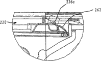
It is (also being shown among Figure 12 B) that how to be positioned in the latch chamber 207 that Figure 20 D shows latch 208.Arc part 261 and arm portion 256 and 258 surround in the assembling post 213, and arm portion 258 is against peripheral wall 212A.Uncinus 262 and release cam 264 extend through the window among the peripheral wall 212D and enter shutter follows the tracks of groove 220, and this groove is formed among the peripheral wall 212D on the opposite side of housing 200.When latch 208 was assembled in the latch chamber 207, latch 208 was in case of bending.Figure 20 E is uncinus 262 and is projected into the more detailed view that shutter is followed the tracks of the release cam 264 in the groove 220.
By latch 208 being placed in the chamber 207, disc devices 206 being placed on disc chamber 210, using assembling post 213 that covering plate 202 is installed to housing 200 and shutter 204 is fixed on the outside of tray salver 200, assemble tray salver 20 thus.Use monolithic housing and the covering plate that is installed to housing one side greatly to simplify the manufacturing of tray salver.These steps will be described in further detail.
At first, latch 208 is placed in the latch chamber 207 in the mode shown in Figure 20 D, and arc part 261 and arm portion 256 and 258 are around assembling post 213, and described assembling post is arranged in latch chamber 207.Arm portion 256 is in abutting connection with inwall 211A, and arm portion 258 is in abutting connection with peripheral arm 212A, and arm portion 260 adjacent perimeter arm 212D.The operation of latch 208 is described below.
Next, disc devices 206 is placed in the disc chamber 210, and data side up.Retaining ring 242 is shelved on the base plate 201 in disc chamber 210.Gap between CD 240 outward flanges and the inwall 211A-211D can be 1.05mm.
Since latch 208 in latch chamber 207 and disc devices 206 in disc chamber 210, thereby covering plate 202 is placed on the top surface of inwall 211A-211D and peripheral arm 212A-212D, closes latch chamber 207 and disc chamber 210.Preferably, the lateral dimension of covering plate 202 is slightly less than the lateral dimension of housing 200, and shallow recess is formed on the inward flange of top surface of peripheral wall 212A-212D.Covering plate 202 is positioned at this recess.Assembly post 213 is orientated the outstanding shrinkage pool 234 about 0.2mm that pass covering plate 202 as.The plastics top that flatiron or heat stake instrument are used to melt assembling post 213 subsequently, and above shrinkage pool 234, form mushroom lid thus.Thus, covering plate 202 is installed to housing 200 by the mushroom cap of top, assembling post 213 tops.The plastics of fusing can remain in the recess around the hole 234, with the outside surface of the substantially flat that is provided at the tray salver 20 on covering plate 202 1 sides.
The final step of assembling process is the outside that shutter 204 is installed in covering plate 202 and housing 200.Because shutter 204 is made by the resilient sheet-like metal, thus protect fin 224 and clamp fin 226 to separate slightly, and can not make shutter 204 permanent strains.What the edge wall 228 of shutter 204 was made is just enough wide, around the edge that is assemblied in housing 200.Shutter 204 is equipped with the clamp fin in the recess 214 of protection fin 224 in the recess 230 of covering plate 202 and housing 200.
Referring to Figure 12 A, shutter is followed the tracks of groove 220 begins and extend to the back edge 218 of housing 220 at guide edge 217 places partial distance again.Shutter is followed the tracks of groove 220 and is formed in the surrounding wall 212D, and as above, peripheral wall 212D makes thicklyer than peripheral wall 212A-212C, to hold groove 220.Figure 21 is the sectional view of peripheral wall 212D in position the time for the shutter 204 obtained at the 21-21 profile line shown in Figure 12 A.Shutter 204 is so installed, and does not follow the tracks of slip in the groove 220 at shutter so that follow the tracks of tab 226A and 226B and latch tab 226C.Follow the tracks of tab 226A and 226B be formed on the shutter 204, allow to have minimum space or " loose " on the position that shutter 204 is free to slide along housing 200 edges.
As mentioned above, window be formed on groove 220 from a side of latch chamber 207 separating groove 220.Window only partly extends upward from the base plate 201 of housing 200.Uncinus 262 and release cam 264 be outstanding to be passed this window and enters groove 220.Shown in Figure 20 B, the whole thickness that uncinus 262 and release cam 264 do not stride across latch 208 extends.This permission uncinus 262 and release cam 264 extend through window and help and regularly latch 208 be positioned in the latch chamber 207.
In order to finish the installation of shutter 204, shutter 204 slides at the edge of the direction upper edge of latch 208 housing 200.When shutter 204 slided in groove 220, latch tab 226C (shown in Figure 15 B) also moved along groove 220.When shutter arrives the position of protection fin 224 covering windows 232, the cam face 265 of latch tab 226C contact uncinus 262.This is shown among Figure 27 A.This causes latch 208 slight curving and force uncinus 262 to get back to window.Shown in Figure 27 B, when latch tab 226C had passed through uncinus 262, latch 208 turned back to its prototype structure and latch tab 226C promptly surperficial 267 being limited in the groove 263 by uncinus 262.This is locked in shutter 204 in the position that window 232 closes, and the data area 250 of protection CD 240 is not damaged.
Figure 22 is the roughly view that is inserted into the tray salver 20 in the tray salver pallet 30 of disk drives.Figure 23 A-23C is the detailed view in the zone 50 of tray salver pallet 30.
Figure 23 A is the vertical view in zone 50, shows the mechanism that is used to discharge shutter 204 when tray salver 20 is inserted in the tray salver pallet 30.Figure 23 B and 23C are the skeleton view in zone 50.Tray salver pallet 30 comprises with functional part, is tablet 302 in the present embodiment, and it is projected into shutter downwards and follows the tracks of in the groove 220.After tray salver 20 had been inserted in the tray salver pallet 30 than short distance, tablet 302 contacted with the guide edge 266 of release cam 264, and forces release cam 264 and uncinus 262 to turn back to window.Referring to Figure 28 A.This has just discharged latch tab 226C and has allowed shutter 204 freely slide along the edge of tray salver 20.Referring to Figure 28 B.After short period, tablet 302 is in abutting connection with the edge 225 of shutter 204, and almost at the same time the shutter insertion section 304 of the elastic load of tray salver pallet 30 engage opening 229 in the edge wall 228 of shutters 204.When the user continued to slide into tray salver 20 in the tray salver pallet 30, tablet 302 kept shutter 204 motionless, so that shutter 204 is along the edge slip of tray salver 20, with the window 232 of opening covering plate 202.When tray salver 20 had been inserted in the tray salver pallet 30 fully, the functional part (not shown) coupling recess 209 (Figure 12 C) of disk drives remained on tray salver 20 in the tray salver pallet 30 securely.
When the user wants when disk drives is removed tray salver 20, the user promotes the button on the disk drives, and it causes functional part to be return from recess 209.Elastic mechanism in the disk drives forces tray salver 20 partly to come out from tray salver pallet 30, exposes the part of the adjacent rear edge 218 of tray salver.When the user manually removed tray salver 20 from tray salver pallet 30, shutter insertion section 304 was retained in the opening 229 of shutter 204, fully closes and is engaged by uncinus 262 up to shutter 204.When the user continued to remove tray salver 20 from disk drives, mentioned from opening 229 subsequently shutter insertion section 304.
Figure 24-26 is for showing the how sectional view of the center pit 244 of bond pad chip module 206 of spindle motors axle 306.Figure 24 is tray salver 20 orientation in this course should residing orientation, and housing 200 has been removed.The similar view that Figure 25 is removed for disc devices 206.The view of Figure 26 for when tray salver has been encased in the disk drives fully, having observed from the downside of tray salver 20.
As shown in figure 25, spindle motors axle 306 comprises ring gripping magnet 305, and its jag part 309 from spindle motors axle 306 is recessed.Clamp magnet 305 can be by the permanent magnet material manufacturing, as NiFe or NiCrFe.As shown in figure 24, when tray salver 20 was inserted in the disk drives fully, spindle motors axle 306 moved upward, so that jag part 309 is inserted in the center pit 244.The conical surface 307 of jag part 309 helps jag part 309 is directed in the center pit 244.Center pit 244 can have the diameter of 4.010-4.022mm, and closely cooperates with respect to jag part 309.When jag part 309 entered in the center pit 244, clamp magnet 305 attracted or the magnetic retaining ring 242 of leaving behind, and as mentioned above, this magnetic retaining ring is glued to the non-data side of CD 240.Two alignment post in the disk drives are assembled in mating holes 222A and the 222B, to guarantee cooperating 20 to be positioned in the disk drives exactly and repeatedly.
Aforesaid embodiments of the invention are exemplary and nonrestrictive.Many alternatives in relative broad range of the present invention are apparent to those skilled in the art.
Claims (17)
1, a kind of tray salver that is used for optical data storage disc comprises:
Single piece of plastic housing with disc chamber, this disc chamber is the border with base plate and sidewall, this sidewall is laterally around this disc chamber;
Be positioned at the optical data storage disc sheet in described disc chamber; With
Be attached to the sheet metal covering plate of described housing, this sheet metal covering plate is in abutting connection with the end face of described sidewall, so that surround described disc chamber, shutter window is formed in the described sheet metal covering plate; With
Shutter around the edge of described tray salver; this shutter comprises the protection fin of contiguous described sheet metal covering plate; this shutter can slide at the edge along described tray salver between open position and off-position; the part of CD is exposed by described shutter window in this open position; and be positioned on the described shutter window at the fin of protection described in this off-position, with hidden this CD.
2, tray salver as claimed in claim 1, wherein, described plastic casing comprises a plurality of plastics assembling posts, each this outstanding hole of passing in the described sheet metal covering plate of plastics assembling post, the mushroom cap is formed on the end of each described assembling post, so that described sheet metal covering plate is remained against described plastic casing.
3, tray salver as claimed in claim 2, wherein, recess forms around each described hole, forms in each mushroom cap in described recess.
4, tray salver as claimed in claim 1, wherein, the data side of described optical data storage disc sheet is towards described sheet metal covering plate.
5, tray salver as claimed in claim 4 wherein, forms around the center pit of annular protrusion edge on the data side of described optical data storage disc sheet.
6, tray salver as claimed in claim 4, wherein, the non-data side of described optical data storage disc sheet is towards the base plate of described housing, and the magnetic retaining ring is attached to the non-data side of described disc, and concentric with the center pit of described disc.
7, tray salver as claimed in claim 1, wherein, described shell dimension is about 36mm * 36mm * 3mm.
8, tray salver as claimed in claim 1, wherein, described sheet metal covering plate roughly is the plane.
9, tray salver as claimed in claim 8, wherein, described shutter comprises clamp fin and edge wall, described edge wall connects described protection fin and described clamp fin.
10, tray salver as claimed in claim 9, wherein, described clamp fin is arranged in the shallow recess that is formed in the described sheet metal covering plate.
11, tray salver as claimed in claim 10, wherein, described sheet metal covering plate is attached to described plastic casing by a plurality of plastics assembling posts, the outstanding hole of passing in the described sheet metal covering plate of each described assembling post, the mushroom cap is formed on the end of each described assembling post, so that described sheet metal covering plate is remained against described plastic casing, annular recessed portion be formed on each described hole around.
12, tray salver as claimed in claim 11, wherein, described sheet metal covering plate comprises a plurality of lateral edges, each described edge is arranged in the recess in one of them sidewall of described plastic casing.
13, a kind of manufacturing is used for the method for the tray salver of optical data storage disc sheet, comprising:
Plastic casing is provided, and described plastic casing has the disc chamber, and described disc chamber is the border with base plate and sidewall, and described sidewall is laterally around described disc chamber, and described plastic casing also comprises a plurality of plastics assembling posts;
Sheet metal with a plurality of holes covering plate is provided;
The optical data storage disc sheet is placed in the described disc chamber;
With the contiguous described plastic casing setting of described sheet metal covering plate, so that described optical data storage disc sheet is enclosed in the described disc chamber, each described assembling post is outstanding to pass described Kong Zhongyi;
The end of heating each described assembling post is to form cap, and described cap remains described sheet metal covering plate against described plastic casing.
14, method as claimed in claim 13 comprises shutter is installed in around the edge of described housing.
15, method as claimed in claim 13 wherein heats the end of each described assembling post and comprises with flatiron and heating.
16, method as claimed in claim 13 wherein heats the end of each described assembling post and comprises with ultrasonic instrument and heating.
17, method as claimed in claim 13 comprises the magnetic retaining ring is glued to described optical data storage disc sheet.
Applications Claiming Priority (2)
| Application Number | Priority Date | Filing Date | Title |
|---|---|---|---|
| US11/209,553 | 2005-08-22 | ||
| US11/209,553 US7603681B2 (en) | 2003-04-25 | 2005-08-22 | Cartridge for miniature optical data storage disc |
Publications (1)
| Publication Number | Publication Date |
|---|---|
| CN101283411A true CN101283411A (en) | 2008-10-08 |
Family
ID=38048952
Family Applications (1)
| Application Number | Title | Priority Date | Filing Date |
|---|---|---|---|
| CNA2006800373782A Pending CN101283411A (en) | 2005-08-22 | 2006-08-18 | Cartridge for miniature optical data storage disc |
Country Status (7)
| Country | Link |
|---|---|
| US (1) | US7603681B2 (en) |
| EP (1) | EP1917663A4 (en) |
| JP (1) | JP2009505328A (en) |
| KR (1) | KR20080036643A (en) |
| CN (1) | CN101283411A (en) |
| TW (1) | TW200709183A (en) |
| WO (1) | WO2007058690A1 (en) |
Families Citing this family (7)
| Publication number | Priority date | Publication date | Assignee | Title |
|---|---|---|---|---|
| US7013476B2 (en) | 2003-04-25 | 2006-03-14 | Vmedia Research, Inc. | Cartridge for miniature optical data storage disc |
| US8177129B2 (en) * | 2004-02-17 | 2012-05-15 | Timothy D. Larin | Interactive multimedia smart affinity card with flash memory |
| US7213749B2 (en) * | 2004-02-17 | 2007-05-08 | R&R Card Systems, Inc. | Interactive multimedia smart affinity card |
| US7983139B2 (en) * | 2007-11-30 | 2011-07-19 | Vmedia Research, Inc. | Small form factor optical data storage disc and cartridge |
| US8315144B2 (en) * | 2004-05-13 | 2012-11-20 | VMO Systems Inc. | Small form factor optical disc drive for use in mobile electronic device |
| JP2009283045A (en) * | 2008-05-20 | 2009-12-03 | Origin Electric Co Ltd | Substrate bonding apparatus |
| US8277919B2 (en) * | 2009-07-23 | 2012-10-02 | VMO Systems, Inc. | Reflective coating for an optical disc |
Family Cites Families (25)
| Publication number | Priority date | Publication date | Assignee | Title |
|---|---|---|---|---|
| US5140489A (en) * | 1989-10-30 | 1992-08-18 | Eastman Kodak Company | Disk cartridge adapted for use with different disk drives |
| JPH07244951A (en) * | 1994-02-28 | 1995-09-19 | Hotsukoo Kk | Disk case |
| JPH07320359A (en) | 1994-05-20 | 1995-12-08 | Ricoh Co Ltd | Optical disc cartridge and optical disc driving apparatus |
| JPH08194977A (en) * | 1995-01-19 | 1996-07-30 | Canon Inc | Cartridge for magnetooptic recording medium |
| JPH08195052A (en) * | 1995-01-19 | 1996-07-30 | Canon Inc | Cartridge for recording medium |
| JP3160752B2 (en) * | 1995-08-15 | 2001-04-25 | シャープ株式会社 | Disk hub, disk cartridge and disk drive |
| JP3632805B2 (en) | 1996-11-07 | 2005-03-23 | 日立マクセル株式会社 | Disc cartridge |
| US6154441A (en) * | 1997-04-17 | 2000-11-28 | Imation Corp. | Method for centering a hub in an optical disc, and an optical storage system using such disc |
| JPH1166792A (en) * | 1997-08-08 | 1999-03-09 | Sony Corp | Disk cartridge |
| TW412728B (en) * | 1998-01-21 | 2000-11-21 | Hitachi Ltd | Disk cartridge |
| US6298533B1 (en) * | 1998-12-02 | 2001-10-09 | Sony Corporation | Assembling device for disc cartridge |
| US20020101816A1 (en) * | 1999-05-20 | 2002-08-01 | Michael F. Braitberg | Removable optical storage device and system |
| JP2001076455A (en) * | 1999-09-03 | 2001-03-23 | Sony Corp | Disk cartridge |
| JP2001076456A (en) * | 1999-09-03 | 2001-03-23 | Sony Corp | Disk cartridge |
| JP2001076457A (en) * | 1999-09-06 | 2001-03-23 | Sony Corp | Disk cartridge |
| JP2001236755A (en) * | 2000-02-22 | 2001-08-31 | Fuji Photo Film Co Ltd | Magnetic disk cartridge |
| US6687215B1 (en) * | 2000-04-12 | 2004-02-03 | Dphi Acquisitions, Inc. | Low profile and medium protecting cartridge assembly |
| JP2002050146A (en) * | 2000-08-02 | 2002-02-15 | Fuji Photo Film Co Ltd | Magnetic disk cartridge |
| JP2002063778A (en) * | 2000-08-18 | 2002-02-28 | Sony Corp | Disk cartridge, method for manufacturing the same, and recording and reproducing system |
| KR100395218B1 (en) * | 2001-03-24 | 2003-08-21 | 한국과학기술연구원 | METHOD FOR MANUFACTURING BaTiO3 BASED POWDERS |
| JP2003100044A (en) * | 2001-09-21 | 2003-04-04 | Hitachi Ltd | Disk cartridge |
| CN100466092C (en) * | 2001-11-09 | 2009-03-04 | 松下电器产业株式会社 | Disc cartridge |
| US6831888B2 (en) * | 2002-03-28 | 2004-12-14 | Imation Corp. | Disk cartridge with single shutter held in multiple open positions |
| JP2004071042A (en) * | 2002-08-06 | 2004-03-04 | Fuji Photo Film Co Ltd | Disk cartridge |
| US7013476B2 (en) * | 2003-04-25 | 2006-03-14 | Vmedia Research, Inc. | Cartridge for miniature optical data storage disc |
-
2005
- 2005-08-22 US US11/209,553 patent/US7603681B2/en not_active Expired - Fee Related
-
2006
- 2006-07-26 TW TW095127404A patent/TW200709183A/en unknown
- 2006-08-18 WO PCT/US2006/032216 patent/WO2007058690A1/en active Application Filing
- 2006-08-18 EP EP06789836A patent/EP1917663A4/en not_active Withdrawn
- 2006-08-18 KR KR1020087006312A patent/KR20080036643A/en not_active Application Discontinuation
- 2006-08-18 JP JP2008528000A patent/JP2009505328A/en active Pending
- 2006-08-18 CN CNA2006800373782A patent/CN101283411A/en active Pending
Also Published As
| Publication number | Publication date |
|---|---|
| EP1917663A4 (en) | 2011-04-20 |
| US20060048167A1 (en) | 2006-03-02 |
| KR20080036643A (en) | 2008-04-28 |
| TW200709183A (en) | 2007-03-01 |
| JP2009505328A (en) | 2009-02-05 |
| US7603681B2 (en) | 2009-10-13 |
| EP1917663A1 (en) | 2008-05-07 |
| WO2007058690A1 (en) | 2007-05-24 |
Similar Documents
| Publication | Publication Date | Title |
|---|---|---|
| CN101283411A (en) | Cartridge for miniature optical data storage disc | |
| US20080282282A1 (en) | Method of fabricating cartridge for miniature optical data storage disc | |
| US5377825A (en) | Compact disc storage case | |
| US5505299A (en) | Storage case for compact discs | |
| US20040037994A1 (en) | Directory read inhibitor for optical storage media | |
| HUH3842A (en) | Optical reading thin film digital data storage device and method for playing a nonround-shape digital data storage device by a common cd-player and player adapter | |
| KR100551904B1 (en) | Storing case for recording medium disc | |
| US7983139B2 (en) | Small form factor optical data storage disc and cartridge | |
| NL8601884A (en) | PLATE CASSETTE. | |
| US6712203B2 (en) | Compact disc case | |
| US8315144B2 (en) | Small form factor optical disc drive for use in mobile electronic device | |
| JPH08504995A (en) | Optical compact disc storage and loading cassette | |
| US5850914A (en) | Crush resistant cartridge case | |
| US20060218570A1 (en) | Disk cartridge | |
| EP2117003A2 (en) | Smart video card | |
| TWI243365B (en) | Magnetic hub assembly for data storage disk | |
| US7787742B2 (en) | Compact optical permanent read-only recording discs with read-write sections enabling users to write data to personalize the discs to the users' needs | |
| EP1212752A1 (en) | Disposable optical storage media and manufacturing method | |
| JP2001348083A (en) | Disk case | |
| US6820276B2 (en) | Disk cartridge with shutter keeper molded as one piece with housing | |
| JP3844955B2 (en) | Optical information recording medium | |
| JP2003054673A (en) | Recording medium storage case | |
| CA2468157A1 (en) | Card for multi-purpose using | |
| JP2000062880A (en) | Cartrige storage case and cartridge | |
| JP2004171712A (en) | Disk cartridge |
Legal Events
| Date | Code | Title | Description |
|---|---|---|---|
| C06 | Publication | ||
| PB01 | Publication | ||
| C10 | Entry into substantive examination | ||
| SE01 | Entry into force of request for substantive examination | ||
| C02 | Deemed withdrawal of patent application after publication (patent law 2001) | ||
| WD01 | Invention patent application deemed withdrawn after publication |
Open date: 20081008 |