JP3601471B2 - Information recording medium cartridge - Google Patents
Information recording medium cartridge Download PDFInfo
- Publication number
- JP3601471B2 JP3601471B2 JP2001140979A JP2001140979A JP3601471B2 JP 3601471 B2 JP3601471 B2 JP 3601471B2 JP 2001140979 A JP2001140979 A JP 2001140979A JP 2001140979 A JP2001140979 A JP 2001140979A JP 3601471 B2 JP3601471 B2 JP 3601471B2
- Authority
- JP
- Japan
- Prior art keywords
- shutter
- slide
- shutter plate
- opening
- recording medium
- Prior art date
- Legal status (The legal status is an assumption and is not a legal conclusion. Google has not performed a legal analysis and makes no representation as to the accuracy of the status listed.)
- Expired - Fee Related
Links
Images


Landscapes
- Feeding And Guiding Record Carriers (AREA)
Description
【0001】
【発明の属する技術分野】
本発明は、磁気ディスクや光ディスク或は光磁気ディスクや相変化型光デイスク等の情報記録媒体を収納した情報記録媒体カートリッジに関するものである。
【0002】
【従来の技術】
情報記録媒体カートリッジとして、例えば図24に示したものが知られている。
【0003】
上記情報記録媒体カートリッジ(以下、単にカートリッジという)101は、表,裏両面に記録層を設けた光ディスクや光磁気ディスク等の情報記録媒体(以下、ディスクという)102と、該ディスク102を回転可能に収納したカートリッジケース(以下、シェルという)103と、該シェル103にスライド可能に取付けられていて、該シェル103の裏,表面に設けた記録及び/又は再生用の開口部(以下、単に開口部という)104を開閉するシャッター105とを備えている。
【0004】
上記シャッター105は、上記シェル103の表面側の開口部104を開閉する第1のシャッター板106と、上記シェル103の裏面側の開口部104を開閉する第2のシャッター板107とを備えている。上記シャッター105は、金属板を折り曲げることにより略コ字状に形成されていて、上記シェル103の表,裏面の開口部104を同時に開閉する。
【0005】
上記カートリッジ101は、記録及び/又は再生装置(以下、ドライブ装置という)に装着されると、該ドライブ装置に設けられたシャッター操作部材でシャッター105が駆動操作され、上記シェル103の表,裏両面の開口部104が同時に開放されるようになっている。
【0006】
そして、図25に示したように、上記カートリッジ101は、上記ディスク102がシェル103の裏面側の開口部104を介して、ドライブ装置のターンテーブル301にチャッキングされて回転駆動されると共に、上記裏面側の開口部104を介して光学ピックアップ302により、上記ディスク102への記録及び/又は再生が行われるようになっている。
【0007】
ところで、上記従来の第1,第2のシャッター板106,107を一体に形成したシャッター105を使用したディスク101は、記録及び/又は再生のために上記シェル103の裏面側の開口部104を開くと、記録及び/又は再生に直接関係しない場合でも上記シェル103の裏面側の開口部104も開かれて、該表面側の開口部104からシェル103内に侵入した塵埃303等がディスク102の上面に付着、堆積するという不具合があった。上記塵埃等の付着は高密度記録の大容量のディスクにとって見過ごすことのできない悪影響を及ぼす。
【0008】
上記不具合を解消するものとして、図26に示した分割シャッターを使用したカートリッジ201が開発された。上記カートリッジ201において、シャッター205は、シェル203の表面203a側の開口部204を開閉する第1のシャッター板206と、上記シェル203の裏面203b側の開口部204を開閉する第2のシャッター板207とからなっていて、これら第1,第2のシャッター板206,207は、単独で移動して、上記開口部204を独自に開閉するようになっている。
【0009】
上記第1,第2のシャッター板206,207は、スライド部材210に取り付けられている。上記スライド部材210は、上記第1のシャッター板206を取付ける第1のスライド部211と、上記第2のシャッター板207を取付ける第2のスライド部212に分割されている。上記第1,第2のスライド部211,212は、上記スライド部材210を移動方向に垂直に2分割することにより形成されている。
【0010】
上記分割シャッターを使用したカートリッジ201がドライブ装置に装着されると、該ドライブ装置に設けられたシャッター開放部材で、上記第2のシャッター板207のみが駆動操作されて、上記シェル203の裏面203b側の開口部204のみが開放され、図27に示したように、上記シェル203の裏面203b側の開口部204を介して、ディスク202はドライブ装置のターンテーブル301にチャッキングされて回転駆動されると共に、光学ピックアップ302により、上記ディスク202への記録及び/又は再生が行われるようになっている。一方、上記第1のシャッター板206は、上記シェル203の表面203a側の開口部204を閉塞していて、該開口部204からの塵埃303等のシェル203内への侵入を防止している。
【0011】
【発明が解決しようとする課題】
ところで、上記従来の分割シャッターを用いたカートリッジ201において、上記第1,第2のスライド部211,212は、上記スライド部材210を単純に移動方向に垂直に2分割した形態に形成されていたために、次に述べるような問題点があった。
(1)図28に示したように、上記第1,第2のスライド部211,212が、傾斜して、上記第1,第2のシャッター板206,207を、上記シェル203の表,裏面から浮き上がらせて、両者の間に隙間Gを発生させて、塵埃が侵入する原因になる。
(2)上記第1,第2のスライド部211,212は、それぞれ独立した存在であるために、シェル203への組み付けも別々に行わなくてはならず、シェル203への組付作業性が悪い。
【0012】
【課題を解決するための手段】
本発明は、上記シャッターを、上記カートリッジケースの表,裏面の一方の面に設けた記録及び/又は再生用の開口部を開閉する第1のシャッター板と、他方の面に設けた記録及び/又は再生用の開口部を開閉する上記第2のシャッター板とに分割すると共に、上記スライド部材を、上記第1のシャッター板を取付ける第1のスライド部と、上記第2のシャッター板を取付ける第2のスライド部に分割した情報記録媒体カートリッジおいて、
上記第1,第2のスライド部を、上記第1のシャッター板又は第2のシャッター板のいずれか一方を取付けるシャッター板取付部と、該シャッター板取付部の底部の一側部に、該シャッター板取付部の幅と略同じ幅で、かつ該シャッター板取付部の長さの略半分の長さに形成されていて、他方のスライド部材のシャッター取付部が載置されるステージ部と、上記シャッター板取付部のスライド方向の一端側の上面側に設けられていて、ドライブ装置のシャッター開放部材が係合するシャッター開放部材係合部と、上記シャッター板取付部のスライド方向の一端側の下面の中央部に設けられた一対のカートリッジケースへの組付脚部と、上記シャッター開放部材係合部の下面に設けられた一対のシェルへの組付脚部とで構成することにより、
上記第1,第2のスライド部の一方のスライド部のシャッター板取付部の一部を、他方のスライド部のステージ部上に重ね合わせた状態で支持することにより、上記第1,第2のスライド部が傾斜して、上記第1,第2のシャッター板が上記カートリッジケースの表,裏面から浮き上がったりするの防止した。
【0013】
また、上記第1,第2のスライド部にバネ係止部を設け、これらバネ係止部に係止したバネ部材での付勢力で上記一方のスライド部のシャッター板取付部の先端を他方のスライド部のシャッター開放部材係合部に係合させて、上記第1,第2のスライド部を結合した状態で上記カートリッジケースに組み付けることが出来るようにした。
【0014】
【発明の実施の形態】
次に、本発明の情報記録媒体カートリッジを(1)全体の概略構成、(2)ディスクの構成、(3)シェルの構成、(4)シャッターの構成、(5)スライド部材の構成、(6)他の実施例、(7)作用の各項に分けて説明する。
(1)情報記録媒体カートリッジ全体の概略構成
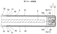
図1は所謂シャッターを閉じた状態の情報記録媒体カートリッジ(以下、カートリッジという)1を表面側から見た斜視図、図2は同裏面側から見た斜視図、図3は裏面側のシャッターを開いた状態の斜視図、図4は同裏面側から見た斜視図である。上記カートリッジ1は、表,裏両面に記録及び/又は再生可能な所謂両面使用のカートリッジとして構成されている。
【0015】
上記カートリッジ1は、ディスク状の情報記録媒体(以下、ディスクという)2と、該ディスク2を回転可能に収納したカートリッジケース(以下、シェルという)3と、該シェル3の表,裏両面に設けられた記録及び/又は再生用の開口部(以下、開口部という)31と、該開口部31を開閉するシャッター4とを備えている。
【0016】
上記シャッター4は、上記シェル3の表面側(後に説明する上ハーフ32側)に設けた開口部31を開閉する第1のシャッター板41と、上記シェル3の裏面側(後に説明する下ハーフ33側)に設けた開口部31を開閉する第2のシャッター板42とを備えている。
【0017】
上記第1,第2のシャッター板41,42は、図1,図2示す上記開口部31を閉塞する第1の位置と、図3,図4に示す開口部31を開放する位置との間をそれぞれ独立に移動するようになっている。
【0018】
上記シャッター4を構成する第1,第2のシャッター板41,42は、上記シェル3の表,裏面に設けた開口部31よりもやや大き目の上記開口部31を完全に閉塞するのに必要な大きさで、かつ上記開口部31を閉塞する第1の位置おいて、これら第1,第2のシャッター板41,42は、シェル3の肉厚方向において略一致して相重なり合う幅W(大きさ)に形成されている。実施例において、上記第1,第2のシャッター板41,42には、同一部材が使用されている。
【0019】
上記第1のシャッター板41は、上記開口部31を閉塞する第1の位置から矢印A方向にスライドして上記開口部31を開放する第2の位置に移動するようになっている。また、上記第2のシャッター板42は、上記矢印A方向とは逆の矢印B方向にスライドして上記開口部31を閉塞する第1の位置から上記開口部4を開放する第2の位置に移動するようになっている。
【0020】
上記シェル3の表,裏面には、上記開口部31を中心にして、その一側部に上記第1,第2のシャッター板41,42の移動エリア5が設けられ、他側部にインデックスカード等のラベル貼着エリア6が設けられている。上記第1,第2のシャッター板41,42は、後に詳しく説明するスライド部材7によりシェル3にスライド可能に取付けられている。
(2)ディスクの構成
図5に示したように、上記ディスク2は、円盤状の記録媒体本体部21と、該記録媒体本体部21の中央部に設けられたセンターハブ22を有している。
【0021】
上記記録媒体本体部21は、例えば図6に示したように、ポリカーボネート(PC)の基板23の内面に記録層24を設け、外面に保護層25を設けた第1,第2の成膜済基板の記録媒体26,27を重ね合わせて接着層28で接着することにより形成されている。上記ディスク2は、センターハブ23がドライブ装置のターンテーブル302にチャッキングされ、第1の記録媒体26の記録層24にドライブ装置の光学ピックアップ装置302によって記録及び/又は再生が可能になると共に、上記ディスク2を裏返すことにより、上記光学ピックアップ装置302により、上記第2の記録媒体27の記録層24への記録及び/又は再生が可能になる。上記記録媒体本体部21は、数GB〜40GB(ギガバイト)の高容量に形成されている。
【0022】
上記センターハブ22は、当然のことながら上記ディスク2の第1の記録媒体26の記録層24に記録及び/又は再生する場合は勿論のこと、上記ディスク2を裏返して装着し、上記第2の記録媒体27の記録層24に記録及び/又は再生を行う場合でも上記ディスク2をドライブ装置のターンテーブル301に確実にチャッキングできる構成になっている。
(3)シェルの構成
上記シェル3は、幅方向(シャッタースライド方向)の中央部に上記開口部31を設けた上ハーフ32と下ハーフ33の前、後、左、右の周壁34a,34b,34c,34d相互を突き合わせて複数のビス35で結合することにより形成されている。上記ビス35の頭部が見えるのが裏面側である。
【0023】
上記シェル3は、上,下ハーフ32,33の前後周壁34aの内側がディスク収納部36になっていると共に、上記上,下ハーフ32,33の前周壁34aの外側がスライド部材組付部37になっている。
【0024】
そして、上記ディスク収納部36内に収納されたディスク2の記録媒体本体部21の表,裏面及びセンターハブ22の表,裏面が上記上,下ハーフ32,33の開口部31に臨むようになっている。
【0025】
上記上,下ハーフ32,33の外面に、上下シャッタースライドエリア5とラベル貼着エリア6が設けられている。上記シャッタースライドエリア5は、上記上,下ハーフ32,33の外面から上記第1,第2のシャッター板41,42の略肉厚ぶんだけ低い位置に形成されていて、上記上,下ハーフ31,32のシャッタースライドエリア5に第1,第2のシャッター板41,42を重ね合わせたときに上記上,下ハーフ32,33の外面と上記第1,第2のシャッター板41,42の外面とが略面一及びもしくは若干低くなるようになっている。また、上記シャッタースライドエリア5の上,下ハーフ32,33の後周壁34b側の端部は、更に一段低いシャッター端部挿入部51になっている。そして、図7に示したように、上記シャッター端部挿入部51に上記第1,第2のシャッター板41,42の端部45が挿入されていて、上記端部45は、上記シャッター端部挿入部51内に取付けられたスライドガイド板52によって上記上,下ハーフ32,33の外面から浮き上がる(捲れ上がる)のを防止されて、上記第1,第2のシャッター板32,33は円滑にスライドを保証されるようになっている。
【0026】
また、上記ラベル貼着エリア6は、上記上,下ハーフ32,33の外面から貼着シートの略肉厚ぶんだけ低くなった位置に形成されていて、図8に示したように上記シート貼着エリア6に2点鎖線で示すシート62を貼着したときに、上記上,下ハーフ32,33の外面と上記シートの外面とが略面一及びもしくは若干低くになるようになっている。
【0027】
図5に示したように、上記上,下ハーフ32,33のスライド部材組付部37の内面には、スライド部材7をスライド可能に取付けるガイド突起38が設けられている。図9に示したように、上記ガイド突起38は、上記上,下ハーフ32,33の前周壁34aの外側に、これら前周壁34aと所定の間隔D1をもって略平行に形成されている。また、上記上,下ハーフ32,33のガイド突起38は、上,下ハーフ32,33を結合した状態において、所定の間隔D2をもって対向するようになっていて、上記間隔D2から後に詳しく説明するスライド部材7の組付脚部77を上記上,下ハーフ32,33のガイド突起38,38の間隔及び上記ガイド突起38と前周壁34aの間に挿入可能になっている(図7参照)。
【0028】
上記上,下ハーフ32,33のガイド突起38には、上記スライド部材7の組付脚部77の挿入を容易にするための所謂面取り状の傾斜面38aが設けられている。また、上記上,下ハーフ32,33のガイド突起38の長さ方向(スライド部材移動方向)の中央部には上記ガイド部材6及びこれに取付けられたシャッター4を上記開口部31を閉塞する第1の位置にセットする位置決め突起39が設けられている。
【0029】
上記シェル3は、成形性及び機械的強度に優れた合成樹脂、例えばポリカーボネート(PC)やABS樹脂等により形成されている。
(4)シャッターの構成
上記シャッター4は、上記上ハーフ32の開口部31を開閉する第1のシャッター板41と、下ハーフ33の開口部31を開閉する第2のシャッター板42とに分割されている。
【0030】
上記第1,第2のシャッター板41,42は、上記開口部31を完全に閉塞できるように上記開口部31よりも若干大き目の幅Wと長さLの長方形状に形成されたシャッター本体部43と、該シャッター本体部43の長さ方向の一端部に設けられたスライド部材取付部44と、上記シャッター本体部43の長さ方向の他端部に設けられていて、上記上,下ハーフ32,33のシャッタースライドエリア5の一端部のシャッター端部挿入部51内に挿入される被挿入側の端部45とを備えている。
【0031】
図10に示したように、上記スライド部材取付部44は、上記シャッター本体部43の一端部に略直角に連設された該シャッター本体部43よりも幅狭の略直角の第1折曲部46と、該第1折曲部46の先端にシャッター本体部43と重なり合う方向に略直角に連設された第2折曲部47と、該第2折曲部47の先端の両端部に上記シャッター本体部43側に向けて略直角に連設された第3折曲部(以下、係合爪という)48とを備えている。なお、上記第1折曲部46にネジ孔46aを設け、該ネジ孔46aを介してネジ46bにより、上記第1折曲部46をスライド部材にネジ止めする構成にしてもよい。
【0032】
上記被挿入側の端部45は、上記シャッター本体部43に対して段差Hをもたせた状態に形成されていて、上記スライドガイド板52の下方のシャッター端部挿入部51内に挿入されるようになっている。
【0033】
上記第1,第2のシャッター板41,42は、所定の形状に打ち抜いたステンレススチールやアルミニウム等の金属板を折り曲げることにより或は合成樹脂等により形成されている。なお、本実施例では、上記第1,第2のシャッター板41,42は、同一部材を使用しているが、例えば、被挿入側の端部45の形状を変えて、意図的に別部材としてもよい。
(5)スライド部材の構成
図11,図12に示したように、上記スライド部材7は、スライド方向(長さ方向)のパーティングラインPL1や肉厚方向のパーティングラインPL2等によって、上記第1のシャッター板41を上記シェル3にスライド可能に取付ける第1のスライド部71と、上記第2のシャッター板42を上記シェル3にスライド可能に取付ける第2のスライド部72とに分割されている。
【0034】
上記第1,第2のスライド部71,72は、上記第1のシャッター板41又は第2のシャッター板42のいずれか一方を取付けるシャッター板取付部73と、該シャッター板取付部73の底部の一側部に、該シャッター取付部73の幅と略同じ幅で、かつ該シャッター取付部73の長さの略半分の長さに形成されていて、他方のスライド部材のシャッター取付部が載置されるステージ部74と、上記シャッター板取付部73のスライド方向の一端側の上面に設けられていて、ドライブ装置のシャッター開放部材(図示省略)が係合するシャッター開放部材係合部材75と、上記シャッター板取付部73のスライド方向の一端部(上記シャッター開放部材係合部75)の下面に設けられたシェル3への一対の第1の組付脚部76と、上記シャッター板取付部73の中央部の下面に設けられた一対の第2の組付脚部77と、上記第1,第2のスライド部71,72の一対の第1の組付脚部76間に設けられたバネ係止部78とを備えている。上記組付脚部76,77は、外側面に上記上,下ハーフ32,33のガイド突起38が導入される溝状の凹部79を備えている。
【0035】
上記第1,第2のスライド部71,72は、同形、同大に形成されていて、第1のスライド部71のシャッター板取付部73を第2のスライド部72のステージ部74上に載置すると共に、上記第2のスライド部72のシャッター板取付部73を第1のスライド部71のステージ部74上に載置し、上記第1,第2のスライド部71,72に設けたバネ係止部78に、バネ部材(コイルスプリング)80の一端部と他端部がそれぞれ係止されている。
【0036】
そして、上記バネ部材80により上記第1,第2のスライド部71,72は、互に牽引されて、上記第1のスライド部71のシャッター板取付部73の先端が上記第2のスライド部72のシャッター開放部材係合部75に当接し、上記第2のスライド部72のシャッター板取付部73の先端が上記第1のスライド部71のシャッター開放部材係合部75に当接して、図11に示したように、上記第1,第2のスライド部71,72は、互に結合された状態になる。
【0037】
上記シャッター板取付部73の先端とシャッター開放部材係合部75の当接部には、互に嵌まり合う凸部81と凹部82が設けられていて、これら凸部81と凹部82の嵌合により、結合状態における上記第1,第2のスライド部71,72の位置ズレ(浮き上がり)を防止するようになっている。
【0038】
上記第1,第2のシャッター板取付部73の内面側の両端部には、所謂面取り状の傾斜面83が設けられていると共に、該傾斜面83の下端には爪係合部84が設けられている。上記第1,第2の組付脚部76,76、77,77の間は、バネ部材80の収納空間になっている。
【0039】
上記バネ係止部78は、図12,図13に示したように、上記第1の組付脚部76の外側面よりも内側に形成されていて、バネ部材80が上記第1,第2のシャッター板取付部73の下面内に収まる状態で取付けられるようになっている。
【0040】
図13に示したように、上記バネ部材80によって結合された第1,第2のスライド部71,72の底面の中央部の第2の組付脚部77,77間には、上記上,下ハーフ32,33のガイド突起38の中央部に設けた位置決め突起39が挿入される隙間85が形成されている。
【0041】
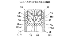
上記バネ部材80によって結合された第1,第2のスライド部71,72は、図14、図15に示したように、上記隙間85を上記シャッター位置決め突起39の位置に合わせた状態で、上記組付脚部76,77側から上記上,下ハーフ32,33の間のスライド部材組付部37に挿入される。上記第1,第2のスライド部71,72が挿入されると、上記組付脚部76,77の下端外側の傾斜面76a,77aが上記ガイド突起38の傾斜面38aに当接し、図16に示したように、上記組付脚部76,77は、内側に弾性変形する。
【0042】
上記組付脚部76,77が上記ガイド突起38を乗り越えると、上記組付脚部76,77は、図17に示したように、弾性復帰して、上記組付脚部76,77の外側面に設けた溝状の凹部79内に上記ガイド突起38が導入されると共に、図18に示したように、上記第1,第2のスライド部71,72の第2の組付脚部77,77間の隙間85に、上記上,下ハーフ32,33のガイド突起38の中央部に設けたシャッター位置決め突起39が侵入して、上記第1,第2のスライド部71,72は、上記第1,第2のシャッター板41,42で上記上,下ハーフ32,33の開閉部31を閉塞する第1の位置にセットされる。
【0043】
上記第1,第2のスライド部71,72は、上記上,下ハーフ32,33に設けたガイド突起38に沿って円滑にスライドするように、潤滑性や耐磨耗性等に優れたポリカーボネートやポリアセタール或はポリプロピレン等の合成樹脂で形成されている。なお、上記第1,第2のスライド部71,72は、同形、同大であり、即ち同一部材として構成してもよいものであり、或は組立上、色分けしてもよい。
【0044】
次に、上記第1,第2のシャッター板41,42の第1,第2のスライド部71,72への組付け方法について説明する。
【0045】
上記第1,第2のシャッター板41,42の第1,第2のスライド部71,72への組付けは、図19に示したように、上記第1,第2のスライド部71,72をシェルに組付けたのち、その上方から上記スライド部材取付部44を下降させて該スライド部材取付部44内に上記第1,第2のスライド部71,72のシャッター板取付部73を挿入することにより行われる。
【0046】
上記第1,第2のシャッター板41,42のスライド部材取付部44の第2折曲部47と係合爪48を、上記第1,第2のスライド部71,72間に挿入すると、図20に示したように、上記スライド部材取付部44の係合爪48が上記傾斜面83に当接して、該傾斜面83によって上記係合爪48及び第2折曲部47は、上記シャッター本体部43との離間する方向に弾性変形して、上記第1,第2のスライド部71,72の更なる挿入を許容する。
【0047】
上記第1,第2のシャッター板41,42の第1折曲部46の内面が上記第1,第2のスライド部71,72の先端面に当接する位置まで挿入されると、上記係合爪48は、上記傾斜面83の位置から外れる。
【0048】
上記係合爪48が上記傾斜面83から外れると、図21に示したように、上記傾斜面83によって上記係合爪48を介して押圧されて弾性変形していた第2折曲部47は、弾性復帰して上記係合爪48が上記爪係合部84に係合し、上記第1,第2のシャッター板41,42は、上記第1,第2のスライド部71,72を介してスライド可能にシェル3に取付けられた状態になるのである。
(6)他の実施例
他の実施例として、図5に示したようなシャッター取付用のネジ46bを使用せずに上記第1,第2のシャッター板41,42と第1,第2のスライド部71,72の結合強度の向上を図った場合を示す。
【0049】
図22に示す実施例においては、第1,第2のシャッター板41,42のスライド部材取付部44の第1折曲部46の上面の一部を凹ませて円形状凹部91を形成すると共に、該凹部91の底面に孔92を形成する。一方、上記第1,第2のスライド部71,72のシャッター板取付部73の上面には上記孔92よりもやや大径の凸部93を突設し、上記第1折曲部46を上記シャッター板取付部73の上面に重ね合わせると、上記孔92を介して、上記凸部93が上記凹部91内に圧入されて、上記第1折曲部46とシャッター板取付部73の位置決めと両者の結合強度の向上を図るようになっている。上記凸部93の上端には抜止用の大径部94を設けてもよい。
【0050】
図23に示す実施例においては、図22に示す実施例の場合と同様に、第1,第2のシャッター板41,42のスライド部材取付部44の第1折曲部46の上面の一部を凹ませて円形状凹部91を形成すると共に、該凹部91の底面に孔92を形成する。一方、上記第1,第2のスライド部71,72のシャッター板取付部73の上面には上記孔91よりも小径の凸部95が突設されている。そして、上記第1折曲部46を上記シャッター板取付部73の上面に重ね合わせ、上記孔92を介して、上記凸部95を上記凹部91内に突出させたのち、超音波溶着装置のホーン100を押し当てて上記凸部95の先端を溶融して、上記孔92よりも大径の頭部(図示省略)をカシメ形成することにより上記第1折曲部46とシャッター板取付部73の位置決めと両者結合強度の向上を図るようになっている。
(7)作用
図1に示したように、上記上ハーフ32を上にし、下ハーフ33を下にした姿勢(以下、正規の姿勢という)で上記カートリッジ1をドライブ装置に挿入すると、該ドライブ装置に設けたシャッター開放部材が第2のスライド部72のシャッター開放部材係合部75に係合して、上記第2のスライド部72は、矢印B方向にスライドし、図3に裏返して示したように、上記第2のスライド部72に取付けられている第2のシャッター板42を上記下ハーフ33の開口部31を開放する第2の位置に移動させる。このとき、上記第2のスライド部72は、一側部が上記組付脚部76,77の溝状の凹部79と上記上,下ハーフ32,33に設けたガイド突起38とによってガイドされ、他側部が上記第1のスライド部材71のステージ部74によってガイドされて、傾斜したりすることなく円滑にスライドする。
【0051】
そして、上記下ハーフ33の開口部31を介して、図6に示したように、上記ディスク2のセンターハブ22はドライブ装置のターンテーブル301にチャッキングされて回転されると共に、光学ピックアップ302により、上記ディスク2の第1の記録媒体26の記録層24への記録及び/又は再生が行われる。
【0052】
また、図2に示したように、下ハーフ33を上にし、上ハーフ32を下にした姿勢(以下、逆の姿勢という)で上記カートリッジ1をドライブ装置に挿入すると、上記ドライブ装置に設けたシャッター開放部材が上記第1のスライド部72のシャッター開放部材係合部75に係合して、上記第1のスライド部71は、一側部が上記組付脚部76,77の溝状の凹部79と上記上,下ハーフ32,33に設けたガイド突起38とによってガイドされ、他側部が上記第2のスライド部材72のステージ部74によってガイドされて、矢印B方向にスライドし、図4に裏返して示したように、上記第1のスライド部71に取付けられている第1のシャッター板41を上記上ハーフ32の開口部31を開放する第2の位置に移動させる。そして、上記上ハーフ32の開口部31を介して、上記ディスク2のセンターハブ22はドライブ装置のターンテーブル301にチャッキングされて回転されると共に、光学ピックアップ302により、上記ディスク2の第2の記録媒体27の記録層24への記録及び/又は再生が行われる。
【0053】
そして、上記正規の姿勢での記録及び/又は再生を行う場合も逆の姿勢で記録及び/又は再生を行う場合も記録及び/又は再生に直接関与しない他方(上方)の開口部31は閉じられた状態に維持されるので、該他方の開口部31からシェル3内に塵埃等が侵入して、ディスク1の表面に付着することが防止される。
【0054】
図3に示す第1のシャッター板41を第1の位置から第2の位置に移動させる場合と、図4に示す第2のシャッター板42を第1の位置から第2の位置に移動させる場合も、上記第1,第2のシャッター板41,42の移動方向は同じであるので、第1のシャッター板41を開放するシャッター開放部材を第2のシャッター板42を開放するシャッター開放部材として兼用できる。
【0055】
【発明の効果】
本発明の情報記録媒体カートリッジには次に述べるような効果がある。
【0056】
(1)請求項1の情報記録媒体カートリッジは、第1,第2のスライド部の一方のスライド部のシャッター板取付部の一部を、他方のスライド部のステージ部で支持したので、該ステージ部によって上記第1,第2のスライド部相互を円滑にスライドさせることが出来る。
【0057】
(2)請求項2の情報記録媒体カートリッジは、バネ部材によって第1,第2のスライド部材が、一体的に結合された状態になるので、取り扱いや上記シェルへの組み付けが容易になる。
【0058】
(3)請求項3の情報記録媒体カートリッジは、一方のスライド部材のシャッター板取付部の先端と、他方のスライド部材のシャッター開放部材係合部の接触面に設けた凹,凸部の嵌合により、第1,第2のスライド部材相互の浮き上がりを防止することが出来る。
【0059】
(4)請求項4の情報記録媒体カートリッジは、第1,第2のスライド部材のバネ係止部を、一対の組付脚部の間で、且つこれら組付脚部の内側に設けたので、上記第1,第2のスライド部材のバネ係止部にバネ部材の一端部と他端部を係止した場合に、該バネ部材を上記スライド部材の下面内に収めることが出来る。
【0060】
(5)請求項5の情報記録媒体カートリッジは、上記第1,第2のスライド部を、同じ形状でかつ同じ大きさに形成したので、両者を共用して部品点数の削減を図ることが出来る。
【図面の簡単な説明】
【図1】カートリッジを表面側から見た斜視図(シャッター閉状態)。
【図2】カートリッジを裏面側から見た斜視図(シャッター閉状態)。
【図3】カートリッジを表面側から見た斜視図(シャッター開状態)。
【図4】カートリッジを裏面側から見た斜視図(シャッター開状態)。
【図5】カートリッジの分解斜視図。
【図6】ディスクの断面図。
【図7】図1のa−a断面図。
【図8】図1のb−b断面図。
【図9】シェルの前周壁側の断面図。
【図10】第1,第2のシャッター板の斜視図。
【図11】スライド部材の斜視図。
【図12】スライド部材の分解斜視図。
【図13】スライド部材の底面図。
【図14】シェルを組立てた状態の斜視図。
【図15】シェルへのスライド部材の組付工程図。
【図16】シェルへのスライド部材の組付工程図。
【図17】シェルへのスライド部材の組付工程図。
【図18】スライド部材が組付けられた状態の要部の側面図。
【図19】シャッター板の組付工程図。
【図20】シャッター板の組付工程図。
【図21】シャッター板の組付工程図。
【図22】他の実施例の断面図。
【図23】他の実施例の断面図。
【図24】従来の一体型シャッターを使用したカートリッジの斜視図。
【図25】ドライブ装置へ装着した状態の断面図。
【図26】従来の分割型シャッターを使用したカートリッジの要部の断面図。
【図27】ドライブ装置へ装着した状態の断面図。
【図28】従来例の問題点を示す断面図。
【符号の説明】
1…カートリッジ、2…ディスク、3…シェル、4…シャッター、7…スライド部材、31…開口部、41,42…第1,第2のシャッター板、71,72…第1,第2のスライド部、73…シャッター板取付部、74…ステージ部、75…シャッター解放部材係合部、76,77…組付脚部、78…バネ係止部、80…バネ部材、81…凸部、82…凹部。[0001]
TECHNICAL FIELD OF THE INVENTION
The present invention relates to an information recording medium cartridge containing an information recording medium such as a magnetic disk, an optical disk, a magneto-optical disk, and a phase-change optical disk.
[0002]
[Prior art]
As an information recording medium cartridge, for example, the one shown in FIG. 24 is known.
[0003]
The information recording medium cartridge (hereinafter, simply referred to as a cartridge) 101 includes an information recording medium (hereinafter, referred to as a disk) 102 such as an optical disk or a magneto-optical disk having a recording layer provided on both front and rear sides, and a
[0004]
The
[0005]
When the
[0006]
Then, as shown in FIG. 25, the
[0007]
By the way, the
[0008]
As a solution to the above problem, a
[0009]
The first and
[0010]
When the
[0011]
[Problems to be solved by the invention]
By the way, in the
(1) As shown in FIG. 28, the first and
(2) Since the first and
[0012]
[Means for Solving the Problems]
According to the present invention, a first shutter plate for opening and closing a recording and / or reproducing opening provided on one surface of the front and back surfaces of the cartridge case, and a recording and / or reproducing device provided on the other surface are provided. Alternatively, the slide member may be divided into the second shutter plate that opens and closes an opening for reproduction, and the slide member may be divided into a first slide unit that mounts the first shutter plate and a second slide plate that mounts the second shutter plate. In the information recording medium cartridge divided into two slide portions,
The first and second slide portions are mounted on a shutter plate mounting portion for mounting either the first shutter plate or the second shutter plate, and the shutter is mounted on one side of a bottom portion of the shutter plate mounting portion. A stage portion having substantially the same width as the width of the plate mounting portion, and being formed to have a length substantially equal to half the length of the shutter plate mounting portion, and a shutter mounting portion of the other slide member being placed; A shutter opening member engaging portion provided on the upper surface of one end of the shutter plate mounting portion in the sliding direction to be engaged with a shutter opening member of the drive device; and a lower surface on one end side of the shutter plate mounting portion in the sliding direction. By constructing a pair of legs to be attached to a pair of cartridge cases provided at the center of the pair, and a pair of legs to be attached to a pair of shells provided on the lower surface of the shutter opening member engaging portion,
By supporting a part of the shutter plate attaching portion of one of the first and second sliding portions on the stage portion of the other sliding portion, the first and second sliding portions are supported. The first and second shutter plates are prevented from floating from the front and back surfaces of the cartridge case by inclining the slide portion.
[0013]
Further, a spring locking portion is provided on the first and second slide portions, and the tip of the shutter plate mounting portion of the one slide portion is moved to the other by the biasing force of the spring member locked by the spring locking portion. The first and second slide portions can be assembled to the cartridge case in a state where the first and second slide portions are connected by engaging the shutter opening member engaging portion of the slide portion.
[0014]
BEST MODE FOR CARRYING OUT THE INVENTION
Next, the information recording medium cartridge of the present invention is (1) an overall configuration, (2) a disk configuration, (3) a shell configuration, (4) a shutter configuration, (5) a slide member configuration, (6) ) The other embodiments will be described separately for each item of (7) Action.
(1) Schematic configuration of entire information recording medium cartridge
FIG. 1 is a perspective view of a so-called information recording medium cartridge (hereinafter referred to as a cartridge) 1 with a shutter closed, viewed from the front side, FIG. 2 is a perspective view of the same viewed from the back side, and FIG. FIG. 4 is a perspective view of the open state, and FIG. The
[0015]
The
[0016]
The
[0017]
The first and
[0018]
The first and
[0019]
The
[0020]
On the front and back surfaces of the
(2) Disc configuration
As shown in FIG. 5, the
[0021]
As shown in FIG. 6, for example, the recording medium
[0022]
It goes without saying that the
(3) Shell configuration
The
[0023]
The
[0024]
The front and back surfaces of the recording medium
[0025]
On the outer surfaces of the upper and
[0026]
The
[0027]
As shown in FIG. 5, a
[0028]
The
[0029]
The
(4) Configuration of shutter
The
[0030]
The first and
[0031]
As shown in FIG. 10, the slide
[0032]
The
[0033]
The first and
(5) Configuration of slide member
As shown in FIGS. 11 and 12, the sliding
[0034]
The first and
[0035]
The first and
[0036]
Then, the first and
[0037]
A
[0038]
At both ends on the inner surface side of the first and second shutter
[0039]
As shown in FIGS. 12 and 13, the
[0040]
As shown in FIG. 13, between the second assembling
[0041]
As shown in FIGS. 14 and 15, the first and
[0042]
When the assembling
[0043]
The first and
[0044]
Next, a method of assembling the first and
[0045]
As shown in FIG. 19, the first and
[0046]
When the second
[0047]
When the inner surfaces of the first
[0048]
When the engaging
(6) Another embodiment
In another embodiment, the first and
[0049]
In the embodiment shown in FIG. 22, a part of the upper surface of the first
[0050]
In the embodiment shown in FIG. 23, as in the embodiment shown in FIG. 22, a part of the upper surface of the first
(7) Action
As shown in FIG. 1, when the
[0051]
Then, as shown in FIG. 6, the
[0052]
As shown in FIG. 2, when the
[0053]
In addition, when the recording and / or reproduction is performed in the normal posture and when the recording and / or reproduction is performed in the reverse posture, the other (upper) opening 31 not directly involved in the recording and / or reproduction is closed. This prevents the dust and the like from entering the
[0054]
The case where the
[0055]
【The invention's effect】
The information recording medium cartridge of the present invention has the following effects.
[0056]
(1) In the information recording medium cartridge according to the first aspect, a part of the shutter plate mounting portion of one of the first and second slide portions is supported by the stage portion of the other slide portion. The first and second sliding portions can be slid smoothly with each other by the portion.
[0057]
(2) In the information recording medium cartridge according to the second aspect, since the first and second slide members are integrally connected by the spring member, handling and assembling to the shell are facilitated.
[0058]
(3) In the information recording medium cartridge according to the third aspect, the leading end of the shutter plate mounting portion of one slide member and the concave and convex portions provided on the contact surface of the shutter opening member engaging portion of the other slide member are fitted. Thereby, it is possible to prevent the first and second slide members from floating.
[0059]
(4) In the information recording medium cartridge according to the fourth aspect, the spring engaging portions of the first and second slide members are provided between the pair of assembly legs and inside the assembly legs. When one end and the other end of the spring member are locked to the spring locking portions of the first and second slide members, the spring member can be accommodated in the lower surface of the slide member.
[0060]
(5) In the information recording medium cartridge according to
[Brief description of the drawings]
FIG. 1 is a perspective view of a cartridge viewed from the front side (shutter closed state).
FIG. 2 is a perspective view of the cartridge viewed from the back side (shutter closed state).
FIG. 3 is a perspective view of the cartridge as viewed from the front side (shutter open state).
FIG. 4 is a perspective view (shutter open state) of the cartridge viewed from the back side.
FIG. 5 is an exploded perspective view of the cartridge.
FIG. 6 is a sectional view of a disk.
FIG. 7 is a sectional view taken along the line aa in FIG. 1;
FIG. 8 is a sectional view taken along line bb of FIG. 1;
FIG. 9 is a sectional view of the shell on the front peripheral wall side.
FIG. 10 is a perspective view of first and second shutter plates.
FIG. 11 is a perspective view of a slide member.
FIG. 12 is an exploded perspective view of a slide member.
FIG. 13 is a bottom view of the slide member.
FIG. 14 is a perspective view showing a state where the shell is assembled.
FIG. 15 is a process diagram of assembling a slide member to a shell.
FIG. 16 is a process diagram of assembling a slide member to a shell.
FIG. 17 is a process diagram of assembling a slide member to a shell.
FIG. 18 is a side view of a main part in a state where the slide member is assembled.
FIG. 19 is an assembly process diagram of the shutter plate.
FIG. 20 is an assembly process diagram of the shutter plate.
FIG. 21 is an assembly process diagram of the shutter plate.
FIG. 22 is a sectional view of another embodiment.
FIG. 23 is a sectional view of another embodiment.
FIG. 24 is a perspective view of a cartridge using a conventional integrated shutter.
FIG. 25 is a sectional view of a state where the apparatus is mounted on a drive device.
FIG. 26 is a cross-sectional view of a main part of a cartridge using a conventional split shutter.
FIG. 27 is a cross-sectional view of a state of being mounted on a drive device.
FIG. 28 is a sectional view showing a problem of the conventional example.
[Explanation of symbols]
DESCRIPTION OF
Claims (5)
上記シャッターは、上記カートリッジケースの表,裏面の一方の面に設けた記録及び/又は再生用の開口部を開閉する第1のシャッター板と、他方の面に設けた記録及び/又は再生用の開口部を開閉する第2のシャッター板とに分割されている情報記録媒体カートリッジおいて、
上記スライド部材は、上記第1のシャッター板を取付ける第1のスライド部と、上記第2のシャッター板を取付ける第2のスライド部に分割され、
上記第1,第2のスライド部は、上記第1のシャッター板又は第2のシャッター板を取付けるシャッター板取付部と、該シャッター板取付部の底部の一側部に、該シャッター板取付部の幅と略同じ幅で、かつ該シャッター板取付部の長さの略半分の長さに形成されていて、他方のスライド部材のシャッター板取付部が重ね合わされるステージ部と、上記シャッター板取付部のスライド方向の一端側の上面側に設けられていて、ドライブ装置のシャッター開放部材が係合するシャッター開放部材係合部と、上記シャッター板取付部のスライド方向の一端側の下面の中央部に設けられたカートリッジケースへの一対の組付脚部と、上記シャッター開放部材係合部の下面に設けられたカートリッジケースへの一対の組付脚部とを備えていることを特徴とする情報記録媒体カートリッジ。A disc-shaped information recording medium, a cartridge case accommodating the information recording medium, a shutter for opening and closing a recording and / or reproducing opening provided on the front and back surfaces of the cartridge case, and And a slide member movably mounted in a direction to open and close the opening,
The shutter includes a first shutter plate that opens and closes a recording and / or reproducing opening provided on one surface of the front and back surfaces of the cartridge case, and a recording and / or reproducing device provided on the other surface. In an information recording medium cartridge divided into a second shutter plate that opens and closes an opening,
The slide member is divided into a first slide portion for mounting the first shutter plate and a second slide portion for mounting the second shutter plate,
The first and second slide portions include a shutter plate mounting portion for mounting the first shutter plate or the second shutter plate, and a shutter plate mounting portion on one side of a bottom portion of the shutter plate mounting portion. A stage portion having substantially the same width as that of the shutter plate mounting portion and having a length substantially equal to half the length of the shutter plate mounting portion, on which the shutter plate mounting portion of the other slide member is superimposed; The shutter opening member engaging portion, which is provided on the upper surface of one end side in the sliding direction of the drive device and is engaged with the shutter opening member of the drive device, It is characterized in that it comprises a pair of mounting legs to the cartridge case provided and a pair of mounting legs to the cartridge case provided on the lower surface of the shutter opening member engaging portion. Information recording medium cartridge to be.
上記第1,第2のスライド部は、バネ係止部を備えていて、
上記バネ係止部には、バネ部材の一端部と他端部が係止されていて、該バネ部材の付勢力によって、上記第1,第2のスライド部の一方のスライド部のシャッター板取付部の先端は、他方のスライド部のシャッター開放部材係合部に係合されていることを特徴とする情報記録媒体カートリッジ。In claim 1,
The first and second slide portions include a spring locking portion,
One end and the other end of a spring member are locked to the spring locking portion, and the shutter plate is attached to one of the first and second slide portions by a biasing force of the spring member. An information recording medium cartridge, wherein a tip of the portion is engaged with a shutter opening member engaging portion of the other slide portion.
上記シャッター板取付部の先端と上記シャッター開放部材係合部との接触面には、互に嵌合する位置決め用の凹,凸部が設けられていることを特徴とする情報記録媒体カートリッジ。In claim 2,
An information recording medium cartridge, characterized in that the contact surface between the tip of the shutter plate mounting portion and the shutter opening member engaging portion is provided with positioning concave and convex portions that fit together.
上記バネ係止部は、上記一対の組付脚部の間で、且つこれら組付脚部の内側に設けられていることを特徴とする情報記録媒体カートリッジ。In claim 2,
The information recording medium cartridge according to claim 1, wherein the spring locking portion is provided between the pair of assembly legs and inside the assembly legs.
上記第1,第2のスライド部は、同じ形状で、且つ同じ大きさに形成されていることを特徴とする情報記録媒体カートリッジ。In claim 1,
An information recording medium cartridge according to claim 1, wherein said first and second slide portions have the same shape and the same size.
Priority Applications (5)
| Application Number | Priority Date | Filing Date | Title |
|---|---|---|---|
| JP2001140979A JP3601471B2 (en) | 2001-05-11 | 2001-05-11 | Information recording medium cartridge |
| KR1020027016133A KR100893807B1 (en) | 2001-03-29 | 2002-03-28 | Information recording medium cartridge |
| EP02707197A EP1376576A4 (en) | 2001-03-29 | 2002-03-28 | Information recording medium cartridge |
| US10/296,800 US6934962B2 (en) | 2001-03-29 | 2002-03-28 | Disc cartridge with mounting part of shutter slide portion arranged on stage of another shutter slide portion |
| PCT/JP2002/003029 WO2002080175A1 (en) | 2001-03-29 | 2002-03-28 | Information recording medium cartridge |
Applications Claiming Priority (1)
| Application Number | Priority Date | Filing Date | Title |
|---|---|---|---|
| JP2001140979A JP3601471B2 (en) | 2001-05-11 | 2001-05-11 | Information recording medium cartridge |
Publications (2)
| Publication Number | Publication Date |
|---|---|
| JP2002334545A JP2002334545A (en) | 2002-11-22 |
| JP3601471B2 true JP3601471B2 (en) | 2004-12-15 |
Family
ID=18987495
Family Applications (1)
| Application Number | Title | Priority Date | Filing Date |
|---|---|---|---|
| JP2001140979A Expired - Fee Related JP3601471B2 (en) | 2001-03-29 | 2001-05-11 | Information recording medium cartridge |
Country Status (1)
| Country | Link |
|---|---|
| JP (1) | JP3601471B2 (en) |
-
2001
- 2001-05-11 JP JP2001140979A patent/JP3601471B2/en not_active Expired - Fee Related
Also Published As
| Publication number | Publication date |
|---|---|
| JP2002334545A (en) | 2002-11-22 |
Similar Documents
| Publication | Publication Date | Title |
|---|---|---|
| US6810005B2 (en) | Disc cartridge | |
| US20080282282A1 (en) | Method of fabricating cartridge for miniature optical data storage disc | |
| US7603681B2 (en) | Cartridge for miniature optical data storage disc | |
| US6583956B2 (en) | Disc cartridge | |
| KR100893807B1 (en) | Information recording medium cartridge | |
| JP3601471B2 (en) | Information recording medium cartridge | |
| JP3601472B2 (en) | Information recording medium cartridge | |
| JP3379231B2 (en) | Disc cartridge and disc clamp device | |
| JP2002334546A (en) | Information recording medium cartreidge | |
| WO2002093576A1 (en) | Information recording medium cartridge | |
| US6560193B2 (en) | Disc cartridge | |
| JP3601476B2 (en) | Information recording medium cartridge | |
| JP3729110B2 (en) | Information recording medium cartridge | |
| US6614622B2 (en) | Disc cartridge shutter opening mechanism including a guide member, an operating member and a transmission member | |
| JP3661607B2 (en) | Information recording medium cartridge | |
| JP2002298539A (en) | Information recording medium cartridge | |
| JP2003091958A (en) | Cartridge for information recording medium | |
| JP3500840B2 (en) | Disk cartridge | |
| JP3380932B2 (en) | Recording medium storage cartridge | |
| JP3003674B2 (en) | Disk cartridge and drive device and erroneous insertion prevention mechanism | |
| JP2000123521A (en) | Disk cartridge | |
| JP2000040324A (en) | Disk cartridge device | |
| JPH1074374A (en) | Disk cartridge | |
| JPH11149738A (en) | Disk cartridge | |
| JP2004127329A (en) | Information recording medium cartridge |
Legal Events
| Date | Code | Title | Description |
|---|---|---|---|
| TRDD | Decision of grant or rejection written | ||
| A01 | Written decision to grant a patent or to grant a registration (utility model) |
Free format text: JAPANESE INTERMEDIATE CODE: A01 Effective date: 20040831 |
|
| A61 | First payment of annual fees (during grant procedure) |
Free format text: JAPANESE INTERMEDIATE CODE: A61 Effective date: 20040913 |
|
| FPAY | Renewal fee payment (event date is renewal date of database) |
Free format text: PAYMENT UNTIL: 20091001 Year of fee payment: 5 |
|
| LAPS | Cancellation because of no payment of annual fees |